EP1265728B1 - Mess- und kontrollsystem für schnittlängen von einzelteilen in einem hochgeschwindigkeitsverfahren - Google Patents
Mess- und kontrollsystem für schnittlängen von einzelteilen in einem hochgeschwindigkeitsverfahren Download PDFInfo
- Publication number
- EP1265728B1 EP1265728B1 EP01905402A EP01905402A EP1265728B1 EP 1265728 B1 EP1265728 B1 EP 1265728B1 EP 01905402 A EP01905402 A EP 01905402A EP 01905402 A EP01905402 A EP 01905402A EP 1265728 B1 EP1265728 B1 EP 1265728B1
- Authority
- EP
- European Patent Office
- Prior art keywords
- web
- piece
- tension
- cut
- feed roll
- Prior art date
- Legal status (The legal status is an assumption and is not a legal conclusion. Google has not performed a legal analysis and makes no representation as to the accuracy of the status listed.)
- Expired - Lifetime
Links
- 238000000034 method Methods 0.000 title claims description 23
- 230000008569 process Effects 0.000 title claims description 22
- 239000000463 material Substances 0.000 claims abstract description 50
- 238000001514 detection method Methods 0.000 claims description 8
- 238000005520 cutting process Methods 0.000 claims description 5
- 238000007689 inspection Methods 0.000 claims description 2
- 238000005259 measurement Methods 0.000 description 14
- 239000013013 elastic material Substances 0.000 description 10
- 230000008901 benefit Effects 0.000 description 5
- 230000000903 blocking effect Effects 0.000 description 3
- 239000000109 continuous material Substances 0.000 description 3
- 230000008859 change Effects 0.000 description 2
- 239000002131 composite material Substances 0.000 description 2
- 230000003247 decreasing effect Effects 0.000 description 2
- 238000012986 modification Methods 0.000 description 2
- 230000004048 modification Effects 0.000 description 2
- 229910000831 Steel Inorganic materials 0.000 description 1
- 238000005304 joining Methods 0.000 description 1
- 239000002648 laminated material Substances 0.000 description 1
- 238000002789 length control Methods 0.000 description 1
- 238000004519 manufacturing process Methods 0.000 description 1
- 230000007246 mechanism Effects 0.000 description 1
- 230000002040 relaxant effect Effects 0.000 description 1
- 239000010959 steel Substances 0.000 description 1
- 239000002699 waste material Substances 0.000 description 1
Images

Classifications
-
- B—PERFORMING OPERATIONS; TRANSPORTING
- B26—HAND CUTTING TOOLS; CUTTING; SEVERING
- B26D—CUTTING; DETAILS COMMON TO MACHINES FOR PERFORATING, PUNCHING, CUTTING-OUT, STAMPING-OUT OR SEVERING
- B26D7/00—Details of apparatus for cutting, cutting-out, stamping-out, punching, perforating, or severing by means other than cutting
- B26D7/08—Means for treating work or cutting member to facilitate cutting
- B26D7/14—Means for treating work or cutting member to facilitate cutting by tensioning the work
-
- B—PERFORMING OPERATIONS; TRANSPORTING
- B26—HAND CUTTING TOOLS; CUTTING; SEVERING
- B26D—CUTTING; DETAILS COMMON TO MACHINES FOR PERFORATING, PUNCHING, CUTTING-OUT, STAMPING-OUT OR SEVERING
- B26D5/00—Arrangements for operating and controlling machines or devices for cutting, cutting-out, stamping-out, punching, perforating, or severing by means other than cutting
- B26D5/20—Arrangements for operating and controlling machines or devices for cutting, cutting-out, stamping-out, punching, perforating, or severing by means other than cutting with interrelated action between the cutting member and work feed
-
- B—PERFORMING OPERATIONS; TRANSPORTING
- B65—CONVEYING; PACKING; STORING; HANDLING THIN OR FILAMENTARY MATERIAL
- B65H—HANDLING THIN OR FILAMENTARY MATERIAL, e.g. SHEETS, WEBS, CABLES
- B65H23/00—Registering, tensioning, smoothing or guiding webs
- B65H23/04—Registering, tensioning, smoothing or guiding webs longitudinally
- B65H23/18—Registering, tensioning, smoothing or guiding webs longitudinally by controlling or regulating the web-advancing mechanism, e.g. mechanism acting on the running web
-
- B—PERFORMING OPERATIONS; TRANSPORTING
- B65—CONVEYING; PACKING; STORING; HANDLING THIN OR FILAMENTARY MATERIAL
- B65H—HANDLING THIN OR FILAMENTARY MATERIAL, e.g. SHEETS, WEBS, CABLES
- B65H35/00—Delivering articles from cutting or line-perforating machines; Article or web delivery apparatus incorporating cutting or line-perforating devices, e.g. adhesive tape dispensers
- B65H35/04—Delivering articles from cutting or line-perforating machines; Article or web delivery apparatus incorporating cutting or line-perforating devices, e.g. adhesive tape dispensers from or with transverse cutters or perforators
-
- B—PERFORMING OPERATIONS; TRANSPORTING
- B65—CONVEYING; PACKING; STORING; HANDLING THIN OR FILAMENTARY MATERIAL
- B65H—HANDLING THIN OR FILAMENTARY MATERIAL, e.g. SHEETS, WEBS, CABLES
- B65H2511/00—Dimensions; Position; Numbers; Identification; Occurrences
- B65H2511/10—Size; Dimensions
- B65H2511/11—Length
-
- B—PERFORMING OPERATIONS; TRANSPORTING
- B65—CONVEYING; PACKING; STORING; HANDLING THIN OR FILAMENTARY MATERIAL
- B65H—HANDLING THIN OR FILAMENTARY MATERIAL, e.g. SHEETS, WEBS, CABLES
- B65H2515/00—Physical entities not provided for in groups B65H2511/00 or B65H2513/00
- B65H2515/30—Forces; Stresses
- B65H2515/31—Tensile forces
-
- B—PERFORMING OPERATIONS; TRANSPORTING
- B65—CONVEYING; PACKING; STORING; HANDLING THIN OR FILAMENTARY MATERIAL
- B65H—HANDLING THIN OR FILAMENTARY MATERIAL, e.g. SHEETS, WEBS, CABLES
- B65H2701/00—Handled material; Storage means
- B65H2701/10—Handled articles or webs
- B65H2701/17—Nature of material
- B65H2701/171—Physical features of handled article or web
- B65H2701/1716—Elastic
-
- Y—GENERAL TAGGING OF NEW TECHNOLOGICAL DEVELOPMENTS; GENERAL TAGGING OF CROSS-SECTIONAL TECHNOLOGIES SPANNING OVER SEVERAL SECTIONS OF THE IPC; TECHNICAL SUBJECTS COVERED BY FORMER USPC CROSS-REFERENCE ART COLLECTIONS [XRACs] AND DIGESTS
- Y10—TECHNICAL SUBJECTS COVERED BY FORMER USPC
- Y10S—TECHNICAL SUBJECTS COVERED BY FORMER USPC CROSS-REFERENCE ART COLLECTIONS [XRACs] AND DIGESTS
- Y10S83/00—Cutting
- Y10S83/929—Particular nature of work or product
- Y10S83/949—Continuous or wound supply
-
- Y—GENERAL TAGGING OF NEW TECHNOLOGICAL DEVELOPMENTS; GENERAL TAGGING OF CROSS-SECTIONAL TECHNOLOGIES SPANNING OVER SEVERAL SECTIONS OF THE IPC; TECHNICAL SUBJECTS COVERED BY FORMER USPC CROSS-REFERENCE ART COLLECTIONS [XRACs] AND DIGESTS
- Y10—TECHNICAL SUBJECTS COVERED BY FORMER USPC
- Y10T—TECHNICAL SUBJECTS COVERED BY FORMER US CLASSIFICATION
- Y10T83/00—Cutting
- Y10T83/04—Processes
- Y10T83/0515—During movement of work past flying cutter
-
- Y—GENERAL TAGGING OF NEW TECHNOLOGICAL DEVELOPMENTS; GENERAL TAGGING OF CROSS-SECTIONAL TECHNOLOGIES SPANNING OVER SEVERAL SECTIONS OF THE IPC; TECHNICAL SUBJECTS COVERED BY FORMER USPC CROSS-REFERENCE ART COLLECTIONS [XRACs] AND DIGESTS
- Y10—TECHNICAL SUBJECTS COVERED BY FORMER USPC
- Y10T—TECHNICAL SUBJECTS COVERED BY FORMER US CLASSIFICATION
- Y10T83/00—Cutting
- Y10T83/04—Processes
- Y10T83/0524—Plural cutting steps
- Y10T83/0538—Repetitive transverse severing from leading edge of work
-
- Y—GENERAL TAGGING OF NEW TECHNOLOGICAL DEVELOPMENTS; GENERAL TAGGING OF CROSS-SECTIONAL TECHNOLOGIES SPANNING OVER SEVERAL SECTIONS OF THE IPC; TECHNICAL SUBJECTS COVERED BY FORMER USPC CROSS-REFERENCE ART COLLECTIONS [XRACs] AND DIGESTS
- Y10—TECHNICAL SUBJECTS COVERED BY FORMER USPC
- Y10T—TECHNICAL SUBJECTS COVERED BY FORMER US CLASSIFICATION
- Y10T83/00—Cutting
- Y10T83/141—With means to monitor and control operation [e.g., self-regulating means]
- Y10T83/148—Including means to correct the sensed operation
-
- Y—GENERAL TAGGING OF NEW TECHNOLOGICAL DEVELOPMENTS; GENERAL TAGGING OF CROSS-SECTIONAL TECHNOLOGIES SPANNING OVER SEVERAL SECTIONS OF THE IPC; TECHNICAL SUBJECTS COVERED BY FORMER USPC CROSS-REFERENCE ART COLLECTIONS [XRACs] AND DIGESTS
- Y10—TECHNICAL SUBJECTS COVERED BY FORMER USPC
- Y10T—TECHNICAL SUBJECTS COVERED BY FORMER US CLASSIFICATION
- Y10T83/00—Cutting
- Y10T83/465—Cutting motion of tool has component in direction of moving work
- Y10T83/474—With work feed speed regulator
-
- Y—GENERAL TAGGING OF NEW TECHNOLOGICAL DEVELOPMENTS; GENERAL TAGGING OF CROSS-SECTIONAL TECHNOLOGIES SPANNING OVER SEVERAL SECTIONS OF THE IPC; TECHNICAL SUBJECTS COVERED BY FORMER USPC CROSS-REFERENCE ART COLLECTIONS [XRACs] AND DIGESTS
- Y10—TECHNICAL SUBJECTS COVERED BY FORMER USPC
- Y10T—TECHNICAL SUBJECTS COVERED BY FORMER US CLASSIFICATION
- Y10T83/00—Cutting
- Y10T83/505—Operation controlled by means responsive to product
Definitions
- This invention is directed to a closed-loop control system for controlling the cut length of a material. More specifically, the cut length is adjusted by changing web tension.
- a number of different manufacturing processes are used to cut continuous webs of material, such as elastic material, including stretch bonded laminates, into discrete lengths prior to placement on a second continuous web. Such processes are typically carried out by open-loop control systems that change web tension through each roll of material to adjust for through-roll variations in cut length.
- open-loop control systems that change web tension through each roll of material to adjust for through-roll variations in cut length.
- a problem encountered with these types of systems is that they assume a consistent material property profile through each roll of material, thereby providing no means to control cut length if the material property profile through each roll of material is different. Also, no means are provided to maintain the web tension at a minimum to reduce cut length variation. Consequently, the higher cut length variation translates into higher material trim waste and poor quality product.
- US 5 480 085 discloses a process for making envelope blanks having predetermined lengths.
- US 3 199 391 discloses a control system for cutting strip steel.
- the present invention is directed to a closed-loop system that maintains a preset cut length of an elastic material, such as a stretch bonded laminate, as the material is cut and placed on a web, taking into account changes in the elastic properties of the material.
- the system has the ability to measure the cut length, compare the average cut length to a target cut length, and to adjust web tension to achieve the target cut length. Also, in a preferred embodiment of the system, the system is able to maintain the web tension at a minimum to reduce cut length variation, and adjust the feed roll speed to achieve the target cut length.
- Elastic and “Elasticity” refer to the tendency of a material, or composite material, to recover its original size and shape after removal of the force causing a deformation.
- Modulus of elasticity refers to a constant that numerically measures or represents the amount of elasticity a material possesses.
- “Operatively connected” means joining, attaching, connecting, or the like, of a first element and a second element either directly or indirectly by means of an additional element disposed between the first element and the second element.
- “Stretch bonded laminate” refers to a composite material having at least two layers in which one layer is a gatherable layer and the other layer is an elastic layer. The layers are joined together when the elastic layer is in an extended condition so that upon relaxing the layers, the gatherable layer is gathered.
- Stress refers to a force tending to cause the extension of a body, or the balancing force within that body resisting the extension.
- the present invention is directed to a system that reduces cut length variation by providing a closed-loop cut length control and a way to reduce web tension at a cut-off module.
- This system has the capability to adjust for changes in elastic material properties in through-roll and roll-to-roll applications.
- This system also allows higher web tension at an unwind end of the system which may be required to overcome roll blocking or idler inertia.
- short term cut length variation can be reduced by providing a way to minimize the tension of the web just prior to a material's entrance into a cut-off module from a driven roll.
- This system is designed to measure and control cut lengths of discrete components in high-speed processes. More particularly, the system is applicable for machines running at speeds in excess of 300 products/min and can even be used with machines running at speeds above 500 products/min. The maximum speed at which the system can be used is limited by the capability of the components used in the system.
- a preferred control system 20 of the present invention for reducing cut length variation in a continuous elastic material 22, including stretch bonded laminates.
- the system 20 includes an unwind spindle 24 from which the elastic material 22 is unwound and fed through the system 20. Once the elastic material 22 leaves the unwind spindle 24, the material travels around a plurality of rolls 26 to a first driving device 28, such as a driven roll.
- the first driving device 28 can be run at a speed greater than the speed of the unwind spindle 24, thereby resulting in relatively high tension which may be required to overcome roll blocking or idler inertia from the unwind spindle 24.
- High tension at the unwind spindle 24 may be required in both through-roll and roll-to-roll applications in order to overcome roll blocking or idler inertia.
- the material 22 is guided around a dancer roll 30 as a means to control the tension between the two driving devices 28, 32. Between the dancer roll 30 and the second driving device 32, the material 22 is guided around a couple of stationary rolls 31. After passing over the second driving device 32, the material 22 is directed around a tension measuring device 34, and the amount of tension in the material 22 is measured at that point.
- the material 22 then makes its way around a web guide 36, shown as a two-part device, to a feed roll 38.
- the web guide 36 is used to control the positioning of the material 22 along a cross-direction of the process. For the purposes of the present invention, the cross-direction lies generally within the plane of the material 22 being transported through the process and is aligned perpendicular to the machine direction.
- the machine direction is indicated by arrows 40 in Fig. 1.
- the material 22 is fed into a cut-off module 42 where the material is cut into pieces 44 of discrete length.
- the cut-off module 42 includes a nip roll 41, an anvil roll 43, and one or more cutting mechanisms (e.g. blades 45) on either the nip roll 41 or the anvil roll 43 for cutting the elastic material 22 into pieces 44 of predetermined length.
- a detection system 48 either on the anvil roll 43 or after the pieces 44 are transferred to a second web 46.
- the preferred location for the detection system 48 is as close to the cut-off module 42 as possible to minimize lag time in the system 20.
- a transfer device 50 or the anvil roll 43, can be used to transfer the pieces 44 from the cut-off module 42 to the second web 46.
- the transfer device 50 can be either a transfer roll or a conveyor.
- the second web 46 can be either a web or a conveyor.
- the detection system 48 may include a vision system or a photoeye.
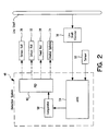
- An example of a preferred detection system 48 is shown schematically in Fig. 2.
- the detection system 48 uses a sensor 52, such as a Banner R55C62QP Color Mark Sensor available from Banner Engineering Corp. of Minneapolis, Minnesota, to detect the presence of each piece 44 on the anvil roll 43 immediately following the cut. Alternatively, as mentioned, the presence of each piece 44 can be detected while the piece 44 is either on the transfer device 50 or on the second web 46.
- the sensor 52 produces a first type of signal, such as a "high” signal, when it detects the presence of the piece 44 and a second type of signal, such as a "low” signal, when it does not detect the presence of the piece 44.
- the first type of signal triggers an automatic registration and inspection system (ARIS) 54 to capture a starting count from a line shaft encoder 56.
- ARIS 54 triggers ARIS 54 to capture an ending count from the line shaft encoder 56.
- ARIS 54 determines the total number of encoder counts during which the sensor 52 detected the presence of each piece 44 and converts the number of encoder counts into an actual millimeter measurement representing the actual cut length of each piece 44.
- a comparator 58 then compares the actual measurement to a target cut length. If the difference between the actual measurement and the target cut length is not equal to zero, the speed of the driving devices 28, 32 and/or the feed roll 38 and/or the unwind spindle 24 is increased or decreased through a proportional integral derivative (PID) control system 60 which is optimally tuned to achieve the target cut length.
- PID proportional integral derivative
- the PID 60 is operatively connected to the driving devices 28, 32 and/or the feed roll 38 and/or the unwind spindle 24, thereby having the capability to increase or decrease speed in view of the target cut length.
- the magnitude of the feed roll speed changes depends on the tension of the elastic material 22 and the material properties of the elastic material.
- the web tension immediately preceding the feed roll 38 is minimized to minimize cut length variation.
- the feed roll 38 can be maintained at a constant speed and the tension in the material 22 preceding the feed roll 38 can be changed by modulating the speeds of driving devices 32, 28 and/or the unwind spindle 24.
- the present invention provides a way to minimize tension into a cut-off module 42 and minimize cut length variation, even in lower modulus elastic materials.
- Cut length setting was increased by 2 mm/product to ⁇ 86 mm/product.
- Cut length setting was decreased by 4 mm/product from original to -80 mm/product.
Landscapes
- Life Sciences & Earth Sciences (AREA)
- Forests & Forestry (AREA)
- Engineering & Computer Science (AREA)
- Mechanical Engineering (AREA)
- Controlling Rewinding, Feeding, Winding, Or Abnormalities Of Webs (AREA)
- Treatment Of Fiber Materials (AREA)
Claims (27)
- Verfahren zum Schneiden eines Materials (22) in Stücke (44) mit einer vorbestimmten Ziellänge, das die Schritte aufweist,Zuführen einer kontinuierlichen Bahn des Materials (22) von einer Zuführrolle (38) zu einem Schneidmodul (42);Messen der Spannung in der Bahn (22); undSchneiden eines Stückes des Materials (44) von der kontinuierlichen Bahn (22);wobei das Verfahren
dadurch gekennzeichnet ist, dasseine tatsächliche Länge des Stückes des Materials (44) gemessen wird;die tatsächliche Länge des Stückes des Materials (44) mit der Ziellänge verglichen wird; unddie Spannung in der Bahn (22) als Antwort auf eine Differenz zwischen der tatsächlichen Länge und der Ziellänge eingestellt wird, bevor die Bahn auf die Zuführrolle (38) stößt. - Verfahren nach Anspruch 1, das ferner den Schritt des Anordnens des Stückes des Materials (44) auf einer zweiten Bahn des Materials (46) umfasst.
- Verfahren nach Anspruch 2, bei dem die tatsächliche Länge des Stückes des Materials (44) gemessen wird, bevor das Stück auf der zweiten Bahn (46) angeordnet wird.
- Verfahren nach Anspruch 2, bei dem die tatsächliche Lange des Stückes des Materials (44) gemessen wird, nachdem das Stück auf der zweiten Bahn (46) angeordnet wurde.
- Verfahren nach Anspruch 1, das den Schritt des Anordnens des Stückes des Materials (44) auf einem Förderer (50) aufweist
- Verfahren nach Anspruch 6, bei dem die tatsächliche Länge des Stückes des Materials (44) gemessen wird, bevor das Stück auf dem Förderer (50) angeordnet wird.
- Verfahren nach Anspruch 5, bei dem tatsächliche Lange des Stückes des Materials (44) gemessen wird, nachdem das Stück auf dem Förderer (50) angeordnet wurde.
- Verfahren nach einem der Ansprüche 1 bis 7, bei dem die Spannung in der Bahn (22) gemessen wird, bevor die Bahn auf die Förderrolle (38) trifft.
- Verfahren nach einem der Ansprüche 1 bis 7, bei dem die Spannung in der Bahn (22) zwischen der Förderrolle (38) und dem Schneidmodul (42) gemessen wird.
- Verfahren nach einem der vorherigen Ansprüche, bei dem der Schritt des Messens der tatsächlichen Länge das Verarbeiten eines ersten Signals, wenn das Stück (44) gemessen wird, und das Verarbeiten eines zweiten Signals, wenn das Stück (44) nicht gemessen wird, umfasst.
- Verfahren nach Anspruch 10, bei dem das erste Signal eine Vorrichtung (64) ansteuert, um eine Startzahl zu erfassen, und das zweite Signal die Vorrichtung (54) ansteuert, um eine Endzahl zu erfassen.
- Verfahren nach Anspruch 11, wobei die Vorrichtung (54) eine Gesamtanzahl von Codierzahlen bestimmt und die Anzahl von Codierzahlen In die tatsächliche Länge konvertiert.
- Verfahren nach Anspruch 12, wobei eine von Null verschledene Differenz zwischen der tatsächlichen Länge und der Ziellänge den Spannungseinstellschritt auslöst.
- Verfahren nach einem der vorhergehenden Ansprüche, bei dem der Spannungseinstellschritt den Schritt des Modulierens der Bahnspannung auf ein Minimum umfasst.
- Vorrichtung zum Herstellen des diskreten Stückes des Materials (44) mit einer Zielschnittlänge, wobei die Vorrichtung aufweist:eine Abwickelspindel (24), von der eine kontinuierliche Bahn des Materials (22) zugeführt wird;ein Schneidmodul (42), in dem ein diskretes Stück des Materials (44) von der kontinuierlichen Bahn (22) abgeschnitten wird;eine Zuführrolle (38), die zwischen der Abwickelspindel (24) und dem Schneidmodul (42) angeordnet ist; undeine Vorrichtung zum Messen der Spannung in der Bahn (34);wobei die Vorrichtung
dadurch gekennzeichnet ist, dasssie ein Erfassungssystem (48) zum Messen einer tatsächlichen Länge des diskreten Stückes des Materials (44), Mittel (58) zum Vergleichen der tatsächlichen Länge des Stückes des Materials (44) mit der Ziellänge und Mittel (24,28,32,38,60) zum Einstellen der Spannung in der Bahn (22) als Antwort auf irgend eine Differenz zwischen der tatsächlichen Länge und der Ziellänge umfasst, bevor die Bahn auf die Förderrolle (38) trifft. - Vorrichtung nach Anspruch 15, wobei die Geschwindigkeit der Förderrolle (38) einstellbar ist.
- Vorrichtung nach Anspruch 15 oder 16, wobei ein Spannungsniveau In der kontinuierlichen Bahn (22) an der Abwickelspindel (24) größer als ein Spannungsniveau in der kontinuierlichen Bahn an dem Schneidmodul (42) ist.
- Vorrichtung nach Anspruch 15, 16 oder 17, die ferner eine Tänzerrolle (20) zwischen der Abwickelspindel (24) und der Förderrolle (36) aufweist.
- Vorrichtung nach Anspruch 18, die ferner eine Bahnführung (36) zwischen der Tänzerrolle (30) und der Förderrolle (38) aufweist.
- Vorrichtung nach einem der Ansprüche 15 bis 19, die ferner eine Transfereinrichtung (50) zwischen dem Schneidmodul (42) und einer zweiten Bahn des Materials (46) aufweist.
- Vorrichtung nach einem der Ansprüche 15 bis 19, die ferner eine Transfereinrichtung (50) zwischen dem Schneidmodul (42) und einem Förderer aufweist.
- Vorrichtung nach einem der Ansprüche 15 bis 21, wobei das Erfassungssystem (48) ein automatisches Erfassungs- und Überprüfungssystem (54) und einen Linien-Drehgeber (56) aufweist.
- Vorrichtung nach einem der Ansprüche 16 bis 22, die ferner ein Proportional-Integral-Ableitungs-Steuersystem (60) aufweist, das wirksam an der Förderrolle (38) befestigt ist.
- Vorrichtung nach einem der Ansprüche 15 bis 22, die ferner ein Proportional-Integral-Ableitungs-Steuersystem (60) aufweist, das wirksam an der Abwickelspindel (24) befestigt ist.
- Vorrichtung nach einem der Ansprüche 15 bis 22, die ferner wenigstens eine Antriebseinrichtung (28,32) aufweist, die zwischen der Abwickelspindel (24) und der Förderrolle (38) angeordnet ist, wobei die wenigstens eine Antriebseinrichtung wirksam an einem Proportional-Integral-Ableitungs-Steuersystem (60) befestigt ist.
- Vorrichtung nach einem der Ansprüche 15 bis 25, wobei die Vorrichtung zum Messen der Spannung in der Bahn (34) die Spannung in der Bahn zwischen der Abwiekelspindel (24) und der Förderrolle (38) misst.
- Vorrichtung nach einem der Ansprüche 15 bis 25, wobei die Vorrichtung zum Messen der Spannung in der Materialbahn die Spannung in der Bahn zwischen der Förderrolle (38) und dem Schneidmodul (42) misst.
Priority Applications (1)
| Application Number | Priority Date | Filing Date | Title |
|---|---|---|---|
| EP06020707A EP1741524B1 (de) | 2000-03-15 | 2001-02-02 | Mess- und Kontrollverfahren von Schnittlänge beim Hochgeschwindigkeitsverfahren zum Schneiden in Einzelteile |
Applications Claiming Priority (3)
| Application Number | Priority Date | Filing Date | Title |
|---|---|---|---|
| US526037 | 1974-11-21 | ||
| US09/526,037 US7004053B1 (en) | 2000-03-15 | 2000-03-15 | System for measuring and controlling cut length of discrete components in a high-speed process |
| PCT/US2001/003555 WO2001068319A1 (en) | 2000-03-15 | 2001-02-02 | System for measuring and controlling cut length of discrete components in a high-speed process |
Related Child Applications (2)
| Application Number | Title | Priority Date | Filing Date |
|---|---|---|---|
| EP06020707A Division EP1741524B1 (de) | 2000-03-15 | 2001-02-02 | Mess- und Kontrollverfahren von Schnittlänge beim Hochgeschwindigkeitsverfahren zum Schneiden in Einzelteile |
| EP06020707.3 Division-Into | 2006-10-02 |
Publications (2)
| Publication Number | Publication Date |
|---|---|
| EP1265728A1 EP1265728A1 (de) | 2002-12-18 |
| EP1265728B1 true EP1265728B1 (de) | 2006-12-13 |
Family
ID=24095659
Family Applications (2)
| Application Number | Title | Priority Date | Filing Date |
|---|---|---|---|
| EP06020707A Expired - Lifetime EP1741524B1 (de) | 2000-03-15 | 2001-02-02 | Mess- und Kontrollverfahren von Schnittlänge beim Hochgeschwindigkeitsverfahren zum Schneiden in Einzelteile |
| EP01905402A Expired - Lifetime EP1265728B1 (de) | 2000-03-15 | 2001-02-02 | Mess- und kontrollsystem für schnittlängen von einzelteilen in einem hochgeschwindigkeitsverfahren |
Family Applications Before (1)
| Application Number | Title | Priority Date | Filing Date |
|---|---|---|---|
| EP06020707A Expired - Lifetime EP1741524B1 (de) | 2000-03-15 | 2001-02-02 | Mess- und Kontrollverfahren von Schnittlänge beim Hochgeschwindigkeitsverfahren zum Schneiden in Einzelteile |
Country Status (6)
| Country | Link |
|---|---|
| US (1) | US7004053B1 (de) |
| EP (2) | EP1741524B1 (de) |
| AU (1) | AU2001233284A1 (de) |
| DE (2) | DE60125151T2 (de) |
| MX (1) | MXPA02009008A (de) |
| WO (1) | WO2001068319A1 (de) |
Cited By (1)
| Publication number | Priority date | Publication date | Assignee | Title |
|---|---|---|---|---|
| CN101650561B (zh) * | 2009-09-09 | 2012-06-27 | 中国电子科技集团公司第四十五研究所 | 单线切割机切割线张力反馈方法 |
Families Citing this family (7)
| Publication number | Priority date | Publication date | Assignee | Title |
|---|---|---|---|---|
| US7047852B2 (en) | 2001-10-24 | 2006-05-23 | Kimberly-Clark Worldwide, Inc. | Feedforward control system for an elastic material |
| FR2899834B1 (fr) * | 2006-04-14 | 2009-01-23 | Eric Ganci | Dispositif de coupe de masque |
| US7891276B2 (en) * | 2007-08-31 | 2011-02-22 | Kimbelry-Clark Worldwide, Inc. | System and method for controlling the length of a discrete segment of a continuous web of elastic material |
| JP2010125763A (ja) * | 2008-11-28 | 2010-06-10 | Olympus Corp | ウェブ搬送装置 |
| CN104136351B (zh) * | 2012-02-29 | 2016-09-07 | 东丽株式会社 | 束状制品的制造方法及制造装置 |
| US10929969B2 (en) | 2016-08-25 | 2021-02-23 | Accusentry, Inc. | Method and apparatus for measuring and profiling absorbent material in an absorbent article |
| CN108748353B (zh) * | 2018-07-13 | 2024-04-05 | 南京赫曼机器人自动化有限公司 | 一种图案膜/纸自适应定长定位切割系统与方法 |
Family Cites Families (37)
| Publication number | Priority date | Publication date | Assignee | Title |
|---|---|---|---|---|
| US3199391A (en) * | 1963-12-26 | 1965-08-10 | Avtron Mfg Inc | Flying shear control and sheet number and length indicator |
| US3324751A (en) * | 1965-03-09 | 1967-06-13 | Cutler Hammer Inc | Increment size adjustment means |
| US3406601A (en) * | 1967-09-19 | 1968-10-22 | Clifford Francis Patrick | Automatic measuring apparatus |
| US3879246A (en) | 1972-09-11 | 1975-04-22 | Robert J Walker | Laminating apparatus and method |
| USRE30628E (en) | 1974-06-07 | 1981-05-26 | Rengo Kabushiki Kaisha (Rengo Co., Ltd.) | Web cutting control system |
| US4020406A (en) | 1974-06-07 | 1977-04-26 | Rengo Kabushiki Kaisha | Web cutting control system |
| US4038127A (en) | 1976-10-08 | 1977-07-26 | Scott Paper Company | Apparatus for controlling the angular orientation of the end of a rolled web |
| US4445408A (en) * | 1979-09-24 | 1984-05-01 | Keith Garland B | Method and apparatus for cutting continuous fibrous material |
| US4375175A (en) | 1981-05-26 | 1983-03-01 | Nemo Industries, Inc. | Towel cutting machine |
| JPS58189710A (ja) * | 1982-04-29 | 1983-11-05 | Mitsubishi Electric Corp | 切断機制御装置 |
| US4543863A (en) * | 1984-01-16 | 1985-10-01 | Wirtz Manufacturing Company, Inc. | Controlled severing of a continuous web |
| US4719575A (en) | 1984-09-14 | 1988-01-12 | Web Printing Control Co., Inc. | Method and apparatus for controlling web handling machinery |
| US4781317A (en) | 1986-08-29 | 1988-11-01 | Adolph Coors Company | Phasing control system for web having variable repeat length portions |
| US4837715A (en) | 1987-01-27 | 1989-06-06 | Kimberly-Clark Corporation | Method and apparatus for detecting the placement of components on absorbent articles |
| US5000725A (en) | 1988-11-07 | 1991-03-19 | Fmc Corporation | Bi-directional registration of servo indexed webs |
| DE3918665A1 (de) | 1989-06-08 | 1990-12-13 | Bhs Bayerische Berg | Verfahren und vorrichtung zum steuern eines formatlaengengerechten schneidens von materialbahnen |
| DE3935614A1 (de) | 1989-10-26 | 1991-05-02 | Frankenthal Ag Albert | Verfahren und einrichtung zum vermindern von makulatur in rollenrotationsdruckmaschinen |
| US5359525A (en) | 1990-05-01 | 1994-10-25 | Kimberly-Clark Corporation | Apparatus and method for registration control of assembled components |
| WO1992005959A1 (en) | 1990-09-27 | 1992-04-16 | Computype, Inc. | Rotary die cutting mechanism |
| US5045135A (en) | 1990-11-15 | 1991-09-03 | Paper Converting Machine Company | Apparatus and method for cutoff register control for diaper machines |
| US5241884A (en) | 1991-10-11 | 1993-09-07 | F. L. Smithe Machine Company, Inc. | Apparatus for changing the length of envelope blanks cut from a continuous web |
| IT1257624B (it) | 1992-01-09 | 1996-02-01 | Gd Spa | Dispositivo per il prelievo del capo del nastro di una bobina nuova ed il suo trasferimento ad una successiva stazione operativa |
| US5235515A (en) | 1992-02-07 | 1993-08-10 | Kimberly-Clark Corporation | Method and apparatus for controlling the cutting and placement of components on a moving substrate |
| ES2090974T3 (es) | 1992-03-24 | 1996-10-16 | Steinemann Ulrich Ag | Procedimiento y dispositivo asi como instalacion para la elaboracion de laminados. |
| US5383988A (en) | 1992-09-10 | 1995-01-24 | Paragon Trade Brands, Inc. | Modular apparatus for fabricating an absorbent article |
| US5413651A (en) | 1993-03-23 | 1995-05-09 | B&H Manufacturing Company | Universal roll-fed label cutter |
| US5380381A (en) | 1993-06-03 | 1995-01-10 | B & H Manufacturing Company, Inc. | Labeling machine with variable speed cutting head |
| US5407513A (en) | 1993-10-14 | 1995-04-18 | The Procter & Gamble Company | Apparatus and process for cyclically accelerating and decelerating a strip of material |
| US5407507A (en) | 1993-10-25 | 1995-04-18 | The Procter & Gamble Company | Method and apparatus for combining a tensioned elastic member with a moving substrate web |
| US5659538A (en) | 1995-03-27 | 1997-08-19 | The Procter & Gambel Company | Diaper registration control system |
| US5818719A (en) | 1995-12-29 | 1998-10-06 | Kimberly-Clark, Worldwide, Inc. | Apparatus for controlling the registration of two continuously moving layers of material |
| US5766389A (en) | 1995-12-29 | 1998-06-16 | Kimberly-Clark Worldwide, Inc. | Disposable absorbent article having a registered graphic and process for making |
| US5932039A (en) | 1997-10-14 | 1999-08-03 | Kimberly-Clark Wordwide, Inc. | Process and apparatus for registering a continuously moving, treatable layer with another |
| CA2267146C (en) | 1996-11-13 | 2004-09-21 | Kimberly-Clark Worldwide, Inc. | Registration process and apparatus for continuously moving elasticized layers having multiple components |
| US6033502A (en) | 1996-11-13 | 2000-03-07 | Kimberly-Clark Worldwide, Inc. | Process and apparatus for registering continuously moving stretchable layers |
| US6092002A (en) | 1996-11-13 | 2000-07-18 | Kimberly-Clark Worldwide, Inc. | Variable tension process and apparatus for continuously moving layers |
| US5930139A (en) | 1996-11-13 | 1999-07-27 | Kimberly-Clark Worldwide, Inc. | Process and apparatus for registration control of material printed at machine product length |
-
2000
- 2000-03-15 US US09/526,037 patent/US7004053B1/en not_active Expired - Lifetime
-
2001
- 2001-02-02 AU AU2001233284A patent/AU2001233284A1/en not_active Abandoned
- 2001-02-02 MX MXPA02009008A patent/MXPA02009008A/es active IP Right Grant
- 2001-02-02 DE DE60125151T patent/DE60125151T2/de not_active Expired - Lifetime
- 2001-02-02 WO PCT/US2001/003555 patent/WO2001068319A1/en not_active Ceased
- 2001-02-02 EP EP06020707A patent/EP1741524B1/de not_active Expired - Lifetime
- 2001-02-02 EP EP01905402A patent/EP1265728B1/de not_active Expired - Lifetime
- 2001-02-02 DE DE60143629T patent/DE60143629D1/de not_active Expired - Lifetime
Cited By (1)
| Publication number | Priority date | Publication date | Assignee | Title |
|---|---|---|---|---|
| CN101650561B (zh) * | 2009-09-09 | 2012-06-27 | 中国电子科技集团公司第四十五研究所 | 单线切割机切割线张力反馈方法 |
Also Published As
| Publication number | Publication date |
|---|---|
| EP1741524B1 (de) | 2010-12-08 |
| US7004053B1 (en) | 2006-02-28 |
| DE60143629D1 (de) | 2011-01-20 |
| DE60125151D1 (de) | 2007-01-25 |
| EP1265728A1 (de) | 2002-12-18 |
| DE60125151T2 (de) | 2007-10-25 |
| WO2001068319A1 (en) | 2001-09-20 |
| MXPA02009008A (es) | 2003-02-12 |
| AU2001233284A1 (en) | 2001-09-24 |
| EP1741524A3 (de) | 2007-07-11 |
| EP1741524A2 (de) | 2007-01-10 |
Similar Documents
| Publication | Publication Date | Title |
|---|---|---|
| EP1440026B1 (de) | Verfahren zur zuführungsregelung eines elastischen materials | |
| AU2002363025A1 (en) | Feedforward control system for an elastic material | |
| US8196497B2 (en) | System and method for controlling the length of a discrete segment of a continuous web of elastic material | |
| US4757930A (en) | Web indicia reference signal generating system | |
| US9221641B2 (en) | Controller and system for controllably rotating a roll of material | |
| EP1265728B1 (de) | Mess- und kontrollsystem für schnittlängen von einzelteilen in einem hochgeschwindigkeitsverfahren | |
| EP2190765B1 (de) | Vorrichtung und verfahren zum steuern einer bahn | |
| CN208037640U (zh) | 用于输送待加工条带段的输送装置 | |
| JP2007169009A (ja) | 複合シート及び物品の製造方法並びに製造装置 | |
| CN224103042U (zh) | 圆刀模切机 | |
| RU2267455C2 (ru) | Транспортный узел для плоских предметов | |
| JPH07178695A (ja) | シート類切断装置 | |
| US20240002185A1 (en) | Electronic Nip Adjustment and Pressure Measurement on Pull Station | |
| US7007603B2 (en) | Conveyor unit for conveying flat objects | |
| CN112875370A (zh) | 接头处理机构及其控制方法 | |
| WO2022233412A1 (de) | Vorrichtung und verfahren zum legen und ausrichten von furnieren zu furnierpaketen im zuge der herstellung von furnierplatten |
Legal Events
| Date | Code | Title | Description |
|---|---|---|---|
| PUAI | Public reference made under article 153(3) epc to a published international application that has entered the european phase |
Free format text: ORIGINAL CODE: 0009012 |
|
| 17P | Request for examination filed |
Effective date: 20021010 |
|
| AK | Designated contracting states |
Kind code of ref document: A1 Designated state(s): AT BE CH CY DE DK ES FI FR GB GR IE IT LI LU MC NL PT SE TR |
|
| AX | Request for extension of the european patent |
Free format text: AL;LT;LV;MK;RO;SI |
|
| RIN1 | Information on inventor provided before grant (corrected) |
Inventor name: HUNTER, DAVID, P. Inventor name: FRANKLIN, KENT, ALLAN Inventor name: LARSEN, CHRISTOPHER, S. Inventor name: BLINCOE, GREGORY, M. Inventor name: CARBONE, HENRY, L. Inventor name: POPP, ROBERT, LEE |
|
| RBV | Designated contracting states (corrected) |
Designated state(s): AT BE CH CY DE ES FR IT LI SE |
|
| GRAP | Despatch of communication of intention to grant a patent |
Free format text: ORIGINAL CODE: EPIDOSNIGR1 |
|
| RBV | Designated contracting states (corrected) |
Designated state(s): DE ES FR IT SE |
|
| GRAS | Grant fee paid |
Free format text: ORIGINAL CODE: EPIDOSNIGR3 |
|
| GRAA | (expected) grant |
Free format text: ORIGINAL CODE: 0009210 |
|
| AK | Designated contracting states |
Kind code of ref document: B1 Designated state(s): DE ES FR IT SE |
|
| REF | Corresponds to: |
Ref document number: 60125151 Country of ref document: DE Date of ref document: 20070125 Kind code of ref document: P |
|
| REG | Reference to a national code |
Ref country code: SE Ref legal event code: TRGR |
|
| PG25 | Lapsed in a contracting state [announced via postgrant information from national office to epo] |
Ref country code: ES Free format text: LAPSE BECAUSE OF FAILURE TO SUBMIT A TRANSLATION OF THE DESCRIPTION OR TO PAY THE FEE WITHIN THE PRESCRIBED TIME-LIMIT Effective date: 20070324 |
|
| ET | Fr: translation filed | ||
| PLBE | No opposition filed within time limit |
Free format text: ORIGINAL CODE: 0009261 |
|
| STAA | Information on the status of an ep patent application or granted ep patent |
Free format text: STATUS: NO OPPOSITION FILED WITHIN TIME LIMIT |
|
| 26N | No opposition filed |
Effective date: 20070914 |
|
| PGFP | Annual fee paid to national office [announced via postgrant information from national office to epo] |
Ref country code: SE Payment date: 20090227 Year of fee payment: 9 |
|
| EUG | Se: european patent has lapsed | ||
| PG25 | Lapsed in a contracting state [announced via postgrant information from national office to epo] |
Ref country code: SE Free format text: LAPSE BECAUSE OF NON-PAYMENT OF DUE FEES Effective date: 20100203 |
|
| REG | Reference to a national code |
Ref country code: FR Ref legal event code: PLFP Year of fee payment: 16 |
|
| REG | Reference to a national code |
Ref country code: FR Ref legal event code: PLFP Year of fee payment: 17 |
|
| PGFP | Annual fee paid to national office [announced via postgrant information from national office to epo] |
Ref country code: FR Payment date: 20170223 Year of fee payment: 17 Ref country code: DE Payment date: 20170227 Year of fee payment: 17 |
|
| REG | Reference to a national code |
Ref country code: DE Ref legal event code: R119 Ref document number: 60125151 Country of ref document: DE |
|
| REG | Reference to a national code |
Ref country code: FR Ref legal event code: ST Effective date: 20181031 |
|
| PG25 | Lapsed in a contracting state [announced via postgrant information from national office to epo] |
Ref country code: DE Free format text: LAPSE BECAUSE OF NON-PAYMENT OF DUE FEES Effective date: 20180901 |
|
| PG25 | Lapsed in a contracting state [announced via postgrant information from national office to epo] |
Ref country code: FR Free format text: LAPSE BECAUSE OF NON-PAYMENT OF DUE FEES Effective date: 20180228 |
|
| PGFP | Annual fee paid to national office [announced via postgrant information from national office to epo] |
Ref country code: IT Payment date: 20200220 Year of fee payment: 20 |