EP1266071B1 - Verfahren und vorrichtung zur behandlung von mahlgut - Google Patents
Verfahren und vorrichtung zur behandlung von mahlgut Download PDFInfo
- Publication number
- EP1266071B1 EP1266071B1 EP01908518A EP01908518A EP1266071B1 EP 1266071 B1 EP1266071 B1 EP 1266071B1 EP 01908518 A EP01908518 A EP 01908518A EP 01908518 A EP01908518 A EP 01908518A EP 1266071 B1 EP1266071 B1 EP 1266071B1
- Authority
- EP
- European Patent Office
- Prior art keywords
- rotor
- steam
- housing
- milling products
- Prior art date
- Legal status (The legal status is an assumption and is not a legal conclusion. Google has not performed a legal analysis and makes no representation as to the accuracy of the status listed.)
- Expired - Lifetime
Links
Images

Classifications
-
- D—TEXTILES; PAPER
- D21—PAPER-MAKING; PRODUCTION OF CELLULOSE
- D21B—FIBROUS RAW MATERIALS OR THEIR MECHANICAL TREATMENT
- D21B1/00—Fibrous raw materials or their mechanical treatment
- D21B1/04—Fibrous raw materials or their mechanical treatment by dividing raw materials into small particles, e.g. fibres
- D21B1/12—Fibrous raw materials or their mechanical treatment by dividing raw materials into small particles, e.g. fibres by wet methods, by the use of steam
- D21B1/14—Disintegrating in mills
- D21B1/26—Driving or feeding arrangements
-
- D—TEXTILES; PAPER
- D21—PAPER-MAKING; PRODUCTION OF CELLULOSE
- D21B—FIBROUS RAW MATERIALS OR THEIR MECHANICAL TREATMENT
- D21B1/00—Fibrous raw materials or their mechanical treatment
- D21B1/04—Fibrous raw materials or their mechanical treatment by dividing raw materials into small particles, e.g. fibres
- D21B1/12—Fibrous raw materials or their mechanical treatment by dividing raw materials into small particles, e.g. fibres by wet methods, by the use of steam
Definitions
- the present invention relates to a device for treating milling products, comprising a housing, a rotor rotably mounted inside the housing and the rotor including at least one pocket for reception of steam-containing milling products, which is to be treated, an inlet in the housing for steam-containing milling products to be passed on to the pocket and an outlet in the housing for milling products to a steam proof discharge device, the pocket being a provided with a radially outwards facing opening, and a steam outlet in the housing.
- the present invention does also relate to a method for treating milling products according to which steam-containing milling products is fed via a housing to a pocket in a rotor rotating in the housing, the milling products is, under influence of the centrifugal force, moved radially outwards towards the circumferential surface of the housing and then thrown out through an outlet for milling products when the pocket has been brought in communication therewith.
- That device comprises a housing in which there is rotatebly arranged a rotor having a number of pockets which in turns are in communication with an inlet for milling products.
- the milling products are thrown out by the centrifugal force through a radially outwards facing opening in the pockets and further to a milling products outlet in the housing when the pocket and the milling product outlet are in communication with each other.
- the steam is then blown out from the pocket into a steam outlet in the housing when they are in communication.
- the inlet and the steam outlet are arranged parallel to the rotor shaft.
- the inlet, the milling products outlet and the steam outlet are angularly displaced in relation to each other.
- the purpose of the present invention is to provide a device which cleans the steam from milling products particles to a higher extent then what take place in prior art.
- That object is attained with a device for treating milling products according to the introductory paragraph which is characterized in that the rotor pocket is provided with a radially inwards facing opening for steam which can be put in communication with the outlet for steam, at least once for every revolution during the rotation of the rotor.
- a method according to the introductory paragraph is characterized by the fact that the remaining steam is thereupon emptied radially inwards when the pocket is brought into communication with the steam outlet of the housing.
- An advantage of this device is that it cleans the steam effectively since remaining particles would have to move against the action of the centrifugal force in order to leave with the outgoing steam, which consequently does not occur.
- the outlet for steam includes a projection provided with at least one channel or a space and at least one radially outwards facing opening, said projection extending a distance in the central area of the rotor so that the opening of the projection can be brought into communication with at least one of the radially inwards facing openings of the rotor pockets.
- the inlet for steam-containing milling products, the outlet for milling products and the outlet for steam are angularly a displaced in relation to each other.
- the inlet for steam-containing milling products is preferably oriented substantially axially in relation to the rotor in a flange of the housing but can of course be arranged in another way, for example tangentially.
- the rotor pocket can have a through passage, in which case the rotor pocket is sealed off at the housing flanges or the rotor exhibit a wall on the one side of the rotor pocket, in which case the rotor pocket is sealed against a flange of the housing.
- the outer circumference of the rotor is preferably sealed relatively the housing.
- the rotor can be provided with an arbitrary number of rotor pockets, but suitably with at least five rotor pockets and preferably eight rotor pockets.
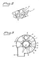
- the device for treating milling products shown in the figures comprises a housing 1 and a rotor 2 which is rotatebly arranged in the housing 1.
- the housing 1 is in turn supported by a framework 4.
- the rotor 2 is driven by a rotor shaft 5 by a drive motor (not shown) in a direction indicated by an arrow in fig. 3.
- a drive motor not shown
- an inlet 6 for milling products containing steam is provided, to which milling products containing steam is supplied by steam from a preceeding processing step, such as a defibrator (not shown).
- the inlet 6 is located in the housing substantially parallel to the rotor shaft 5 at a radial distance from the centre of rotation corresponding to the radial distance where pockets 8 are located in the rotor 2. In the shown case there are eight pockets 8 but their number can naturally be varied as suitable.
- the milling products containing steam is conducted into a pocket 8 in the rotor 2, whereupon the next pocket is filled and so on, during the rotation of the rotor 2.
- the pockets 8 can be axially open, at least towards the inlet 6, with just one partitian 9 between themselves, as is shown in fig. 2, or they can have a lateral wall facing a second flange 10 in the housing 1. Sealing rings 11 can be provided between the rotor 2 and the housing 1.
- the pockets 8 are open radially outwards or have openings emerging radially outwards.
- the pocket 8, filled with steam-containing milling products is brought during the continually rotation of the rotor 2 from the inlet to co-inside with a corresponding opening in the housing 1, an outlet 12 for milling products.
- the centrifugal force transports the milling products in the pocket 8 radially outwards towards the delimiting circumference 13 of the housing 1, so that the milling products and the steam are separated, i.e. the steam is cleaned from milling products which passes out through the outlet 12 when the pocket 8 and outlet 12 are brought into communication.
- the outlet 12 leads on to a steam proof discharge device for the milling products, such as a plug screw (not shown), which transports the milling products further while forming a steam proof pulp plug, which is prior art in this art.
- Each pocket 8 is at its bottom provided with a radially inwards facing opening 14, the size of which, in the shown case, corresponds to about half of the bottom area, see figs. 2 and 3.
- the remaining steam which can not disappear out through the steam proof discharge device, is conducted, during the rotation of the rotor 2 until the radially inwards facing opening 14 of the pocket 8 co-insides with an opening 18, to an outlet for steam in the housing 1.
- the opening 18 should have such a size that it corresponds to one opening 14 of a rotor pocket, but can be larger, for example cover two subsequent rotor pocket openings 14 (not shown).
- the steam which was integrated in the milling products and which supplied the milling products to the housing 1, and any steam formed during the processing of the milling products in the housing 1 blow out through the steam outlet, whereupon the energy content of the steam is taken care of in some known manner.
- the outlet for steam includes a portion projecting from the housing 1, such as a drum or casing 16 which protrudes a distance into the centre of the rotor 2, i.e. preferably equally far as the extension of the openings 14 of the pockets 8.
- the drum 16 protrudes about midway into the centre of the rotor 2.
- the drum 16 preferably has the shape of a conically tapering cylinder with walls and a bottom sealing against the rotor 2 and the housing 1 except at the opening 18 and the opening at the outlet in the housing 1.
- a channel or a cavity 17 is formed inside the drum 16 which is in communication with the opening 18 emerging radially outwards towards the rotor. Alternatively several openings 18 can be located in the drum 16 (not shown).
- the drum 16 can preferably be turned so that the user can select a suitable position for the opening 18. Accordingly, the drum 16 seals off the inwardly facing openings 14 of the rotor pockets 8 except at the opening 18.
- the outlet channel 15 is provided in flange 7, which channel 15 transports the steam onwards for continued use, as described above.
- the inlet for steam-containing milling products 6, the outlet for milling products 12 and the outlet 15 for steam are angularly displaced in relation to each other. They are also preferably located in that succession with reference to the rotational direction of the rotor 2, see fig. 3.
Landscapes
- Engineering & Computer Science (AREA)
- Life Sciences & Earth Sciences (AREA)
- Wood Science & Technology (AREA)
- Mechanical Engineering (AREA)
- Crushing And Grinding (AREA)
- Apparatus Associated With Microorganisms And Enzymes (AREA)
- Finish Polishing, Edge Sharpening, And Grinding By Specific Grinding Devices (AREA)
- Crushing And Pulverization Processes (AREA)
- Drying Of Solid Materials (AREA)
Claims (10)
- Vorrichtung zur Behandlung von Mahlprodukten, umfassend ein Gehäuse (1), einen drehbar im Gehäuse (1) montierten Rotor (2), der wenigstens eine Tasche (8) zur Aufnahme von zu behandelnden Dampf enthaltenden Mahlprodukten umfasst, einen Einlass (6) im Gehäuse (1) zum Durchlassen von Dampf enthaltenden Mahlprodukten zur Tasche (8), und einen Auslass im Gehäuse (1) für Mahlprodukte zu einer dampfdichten Austosseinrichtung, wobei die Tasche (8) wenigstens teilweise radial nach außen offen ist, und einen Dampfauslass im Gehäuse (1), dadurch gekennzeichnet, dass die Rotortasche (8) mit einer radial nach innen weisenden Öffnung (14) für Dampf ausgestattet ist, die so angeordnet ist, dass sie mit den Dampfauslässen (15, 16, 17, 18) des Gehäuses (1) wenigstens ein Mal pro Umdrehung während der Drehung des Rotors (2) kommuniziert.
- Vorrichtung nach Anspruch 1, bei welcher der Auslass (15, 16, 17, 18) für Dampf im Gehäuse (1) eine Trommel (16) umfasst, welche mit wenigstens einem Kanal oder Hohlraum (17) und wenigstens einer radial nach außen weisenden Öffnung (18) ausgestattet ist, wobei die Trommel (16) eine Strecke in den zentralen Bereich des Rotors (2) vorsteht, so dass die Öffnung (18) der Trommel (16) mit wenigstens einer der radial nach innen weisenden Öffnungen (14) der Rotortaschen (8) kommunizieren kann.
- Vorrichtung nach Anspruch 1 oder 2, bei welcher der Einlass (6) für Dampf enthaltende Mahlprodukte, der Auslass (12) für Mahlprodukte und der Auslass (18) für Dampf im Winkel relativ zueinander versetzt sind.
- Vorrichtung nach Anspruch 1, 2 oder 3, bei welcher der Einlass (6) für Dampf enthaltende Mahlprodukte mit Bezug auf den Rotor (2) im Wesentlichen axial in einem Endflansch des Gehäuses (1) angeordnet ist.
- Vorrichtung nach Anspruch 4, bei welcher der Einlass (6) für Dampf enthaltende Mahlprodukte im Wesentlichen im gleichen radialen Abstand angeordnet ist wie die Rotortasche (8).
- Vorrichtung nach einem der vorhergehenden Ansprüche, bei welcher die Rotortasche (8) durchgehend ist, wobei die Rotortasche (8) gegen die Endflansche (7, 10) im Gehäuse (1) abgedichtet ist (bei 11).
- Vorrichtung nach einem der Ansprüche 1 bis 5, bei welcher der Rotor (2) auf einer Seite der Rotortasche (8) eine Wand aufweist, wobei die Rotortasche (8) gegen einen Endflansch (7) im Gehäuse (1) abgedichtet ist.
- Vorrichtung nach einem der vorhergehenden Ansprüche, bei welcher der Rotor wenigstens fünf Rotortaschen (8) und vorzugsweise acht Rotortaschen (8) umfasst.
- Vorrichtung nach einem der vorhergehenden Ansprüche, bei welcher der äußere Umfang des Rotors (2) gegen das Gehäuse (1) abgedichtet ist.
- Verfahren zur Behandlung von Mahlprodukten, bei welchem Dampf enthaltende Mahlprodukte über ein Gehäuse (1) zu einer Tasche (8) in einem im Gehäuse (1) rotierenden Rotor (2) geleitet werden, wobei die Mahlprodukte durch die Zentrifugalkraft radial nach außen zur Umfangfläche des Gehäuses (1) geleitet werden und von dort durch einen Auslass (12) für Mahlprodukte ausgestoßen werden, wenn der Auslass mit der Tasche (8) kommuniziert, dadurch gekennzeichnet, dass der verbleibende Dampf danach radial nach innen entleert wird, wenn die Tasche (8) mit dem Dampfauslass (15, 18) des Gehäuses (1) kommuniziert.
Applications Claiming Priority (3)
| Application Number | Priority Date | Filing Date | Title |
|---|---|---|---|
| SE0000752A SE516001C2 (sv) | 2000-03-07 | 2000-03-07 | Anordning och förfarande för behandling av ånginblandat malgods |
| SE0000752 | 2000-03-07 | ||
| PCT/SE2001/000287 WO2001066853A1 (en) | 2000-03-07 | 2001-02-13 | Apparatus and method for treating milling products |
Publications (2)
| Publication Number | Publication Date |
|---|---|
| EP1266071A1 EP1266071A1 (de) | 2002-12-18 |
| EP1266071B1 true EP1266071B1 (de) | 2005-08-17 |
Family
ID=20278721
Family Applications (1)
| Application Number | Title | Priority Date | Filing Date |
|---|---|---|---|
| EP01908518A Expired - Lifetime EP1266071B1 (de) | 2000-03-07 | 2001-02-13 | Verfahren und vorrichtung zur behandlung von mahlgut |
Country Status (8)
| Country | Link |
|---|---|
| US (1) | US6793165B2 (de) |
| EP (1) | EP1266071B1 (de) |
| AT (1) | ATE302302T1 (de) |
| AU (1) | AU2001236262A1 (de) |
| CA (1) | CA2402109C (de) |
| DE (1) | DE60112730T2 (de) |
| SE (1) | SE516001C2 (de) |
| WO (1) | WO2001066853A1 (de) |
Families Citing this family (7)
| Publication number | Priority date | Publication date | Assignee | Title |
|---|---|---|---|---|
| SE519363C2 (sv) * | 2002-03-07 | 2003-02-18 | Lars Obitz | Slussmatare |
| US7933661B2 (en) * | 2004-02-04 | 2011-04-26 | Medtronic, Inc. | Lead retention means |
| US8708266B2 (en) | 2010-12-09 | 2014-04-29 | Mark E. Koenig | System for crushing with screw porition that increases in diameter |
| US9403336B2 (en) | 2010-12-09 | 2016-08-02 | Mark E. Koenig | System and method for crushing and compaction |
| US9346624B2 (en) | 2011-11-04 | 2016-05-24 | Mark E. Koenig | Cantilevered screw assembly |
| US9132968B2 (en) | 2011-11-04 | 2015-09-15 | Mark E. Koenig | Cantilevered screw assembly |
| US9821962B2 (en) | 2015-12-14 | 2017-11-21 | Mark E. Koenig | Cantilevered screw assembly |
Family Cites Families (2)
| Publication number | Priority date | Publication date | Assignee | Title |
|---|---|---|---|---|
| SE9001612L (sv) | 1990-05-04 | 1991-11-05 | Lars Obitz | Anordning foer behandling av malgods |
| SE510247C2 (sv) * | 1990-05-04 | 1999-05-03 | Lars Obitz | Anordning för behandling av malgods |
-
2000
- 2000-03-07 SE SE0000752A patent/SE516001C2/sv not_active IP Right Cessation
-
2001
- 2001-02-13 US US10/220,240 patent/US6793165B2/en not_active Expired - Lifetime
- 2001-02-13 EP EP01908518A patent/EP1266071B1/de not_active Expired - Lifetime
- 2001-02-13 AU AU2001236262A patent/AU2001236262A1/en not_active Abandoned
- 2001-02-13 DE DE60112730T patent/DE60112730T2/de not_active Expired - Lifetime
- 2001-02-13 WO PCT/SE2001/000287 patent/WO2001066853A1/en not_active Ceased
- 2001-02-13 AT AT01908518T patent/ATE302302T1/de active
- 2001-02-13 CA CA002402109A patent/CA2402109C/en not_active Expired - Lifetime
Also Published As
| Publication number | Publication date |
|---|---|
| DE60112730D1 (de) | 2005-09-22 |
| SE0000752D0 (sv) | 2000-03-07 |
| US6793165B2 (en) | 2004-09-21 |
| CA2402109A1 (en) | 2001-09-13 |
| SE0000752L (sv) | 2001-09-08 |
| WO2001066853A1 (en) | 2001-09-13 |
| DE60112730T2 (de) | 2006-06-29 |
| AU2001236262A1 (en) | 2001-09-17 |
| ATE302302T1 (de) | 2005-09-15 |
| US20030019962A1 (en) | 2003-01-30 |
| EP1266071A1 (de) | 2002-12-18 |
| SE516001C2 (sv) | 2001-11-05 |
| CA2402109C (en) | 2008-09-16 |
Similar Documents
| Publication | Publication Date | Title |
|---|---|---|
| EP1266071B1 (de) | Verfahren und vorrichtung zur behandlung von mahlgut | |
| US4754935A (en) | Method and apparatus for refining fibrous material | |
| EP0839226B1 (de) | Verfahren zur behandlung eines papierzellstoffes und vorrichtung dafür | |
| TW444077B (en) | Method and apparatus for screening waste paper pulp | |
| US4167249A (en) | Stock pulper for pulping and sorting waste paper | |
| US6945487B1 (en) | Feeding apparatus for cellulosic material | |
| US5064125A (en) | Pulper | |
| CA2041732C (en) | Apparatus for the treatment of milling products | |
| CA2037045C (en) | Method and apparatus for pressurized refining of lignocellulose material | |
| JPS60500723A (ja) | 繊維パルプ製造用の方法と装置 | |
| CA2517228C (en) | Sluice feeder | |
| CA1056637A (en) | Continuous flow multistate dewatering apparatus for removing water from an aqueous suspension of pulp material while being conveyed to a steam pressurized reaction vessel | |
| CN102356195B (zh) | 用于处理纤维素纸浆的结构、系统和方法 | |
| SE503362C2 (sv) | Trumraffinör | |
| FI108779B (fi) | Menetelmä paperi- tai kartonkitehtaan täyteainepitoisten rejektivirtojen käsittelemiseksi ja laitteen käyttö | |
| US3845910A (en) | Inlets for a double disc refiner | |
| RU2096983C1 (ru) | Способ измельчения преимущественно зерна и устройство для его осуществления | |
| JPH0559681A (ja) | 製紙用分離装置 | |
| WO2000069543A1 (en) | Separation device | |
| EP0273018A3 (de) | Vorrichtung zum Defibrieren und Sortieren von Papierbrei in der Papierfabrikationsindustrie | |
| JPS6332920B2 (de) | ||
| SU1710624A2 (ru) | Сортировка волокнистой суспензии | |
| JPH06192982A (ja) | 製紙用離解兼除塵装置 | |
| JPH08164346A (ja) | 製紙用分離装置 | |
| JPH0143439Y2 (de) |
Legal Events
| Date | Code | Title | Description |
|---|---|---|---|
| PUAI | Public reference made under article 153(3) epc to a published international application that has entered the european phase |
Free format text: ORIGINAL CODE: 0009012 |
|
| 17P | Request for examination filed |
Effective date: 20020926 |
|
| AK | Designated contracting states |
Kind code of ref document: A1 Designated state(s): AT BE CH CY DE DK ES FI FR GB GR IE IT LI LU MC NL PT SE TR |
|
| AX | Request for extension of the european patent |
Free format text: AL;LT;LV;MK;RO;SI |
|
| GRAP | Despatch of communication of intention to grant a patent |
Free format text: ORIGINAL CODE: EPIDOSNIGR1 |
|
| GRAS | Grant fee paid |
Free format text: ORIGINAL CODE: EPIDOSNIGR3 |
|
| GRAA | (expected) grant |
Free format text: ORIGINAL CODE: 0009210 |
|
| AK | Designated contracting states |
Kind code of ref document: B1 Designated state(s): AT BE CH CY DE DK ES FI FR GB GR IE IT LI LU MC NL PT SE TR |
|
| PG25 | Lapsed in a contracting state [announced via postgrant information from national office to epo] |
Ref country code: IT Free format text: LAPSE BECAUSE OF FAILURE TO SUBMIT A TRANSLATION OF THE DESCRIPTION OR TO PAY THE FEE WITHIN THE PRESCRIBED TIME-LIMIT;WARNING: LAPSES OF ITALIAN PATENTS WITH EFFECTIVE DATE BEFORE 2007 MAY HAVE OCCURRED AT ANY TIME BEFORE 2007. THE CORRECT EFFECTIVE DATE MAY BE DIFFERENT FROM THE ONE RECORDED. Effective date: 20050817 Ref country code: BE Free format text: LAPSE BECAUSE OF FAILURE TO SUBMIT A TRANSLATION OF THE DESCRIPTION OR TO PAY THE FEE WITHIN THE PRESCRIBED TIME-LIMIT Effective date: 20050817 Ref country code: LI Free format text: LAPSE BECAUSE OF FAILURE TO SUBMIT A TRANSLATION OF THE DESCRIPTION OR TO PAY THE FEE WITHIN THE PRESCRIBED TIME-LIMIT Effective date: 20050817 Ref country code: CH Free format text: LAPSE BECAUSE OF FAILURE TO SUBMIT A TRANSLATION OF THE DESCRIPTION OR TO PAY THE FEE WITHIN THE PRESCRIBED TIME-LIMIT Effective date: 20050817 Ref country code: TR Free format text: LAPSE BECAUSE OF FAILURE TO SUBMIT A TRANSLATION OF THE DESCRIPTION OR TO PAY THE FEE WITHIN THE PRESCRIBED TIME-LIMIT Effective date: 20050817 Ref country code: NL Free format text: LAPSE BECAUSE OF FAILURE TO SUBMIT A TRANSLATION OF THE DESCRIPTION OR TO PAY THE FEE WITHIN THE PRESCRIBED TIME-LIMIT Effective date: 20050817 |
|
| REG | Reference to a national code |
Ref country code: GB Ref legal event code: FG4D |
|
| REG | Reference to a national code |
Ref country code: CH Ref legal event code: EP |
|
| REG | Reference to a national code |
Ref country code: IE Ref legal event code: FG4D |
|
| REF | Corresponds to: |
Ref document number: 60112730 Country of ref document: DE Date of ref document: 20050922 Kind code of ref document: P |
|
| PG25 | Lapsed in a contracting state [announced via postgrant information from national office to epo] |
Ref country code: DK Free format text: LAPSE BECAUSE OF FAILURE TO SUBMIT A TRANSLATION OF THE DESCRIPTION OR TO PAY THE FEE WITHIN THE PRESCRIBED TIME-LIMIT Effective date: 20051117 Ref country code: SE Free format text: LAPSE BECAUSE OF FAILURE TO SUBMIT A TRANSLATION OF THE DESCRIPTION OR TO PAY THE FEE WITHIN THE PRESCRIBED TIME-LIMIT Effective date: 20051117 Ref country code: GR Free format text: LAPSE BECAUSE OF FAILURE TO SUBMIT A TRANSLATION OF THE DESCRIPTION OR TO PAY THE FEE WITHIN THE PRESCRIBED TIME-LIMIT Effective date: 20051117 |
|
| PG25 | Lapsed in a contracting state [announced via postgrant information from national office to epo] |
Ref country code: ES Free format text: LAPSE BECAUSE OF FAILURE TO SUBMIT A TRANSLATION OF THE DESCRIPTION OR TO PAY THE FEE WITHIN THE PRESCRIBED TIME-LIMIT Effective date: 20051128 |
|
| PG25 | Lapsed in a contracting state [announced via postgrant information from national office to epo] |
Ref country code: PT Free format text: LAPSE BECAUSE OF FAILURE TO SUBMIT A TRANSLATION OF THE DESCRIPTION OR TO PAY THE FEE WITHIN THE PRESCRIBED TIME-LIMIT Effective date: 20060117 |
|
| NLV1 | Nl: lapsed or annulled due to failure to fulfill the requirements of art. 29p and 29m of the patents act | ||
| PG25 | Lapsed in a contracting state [announced via postgrant information from national office to epo] |
Ref country code: IE Free format text: LAPSE BECAUSE OF NON-PAYMENT OF DUE FEES Effective date: 20060213 Ref country code: GB Free format text: LAPSE BECAUSE OF NON-PAYMENT OF DUE FEES Effective date: 20060213 |
|
| PG25 | Lapsed in a contracting state [announced via postgrant information from national office to epo] |
Ref country code: MC Free format text: LAPSE BECAUSE OF NON-PAYMENT OF DUE FEES Effective date: 20060228 Ref country code: LU Free format text: LAPSE BECAUSE OF NON-PAYMENT OF DUE FEES Effective date: 20060228 |
|
| REG | Reference to a national code |
Ref country code: CH Ref legal event code: PL |
|
| PLBE | No opposition filed within time limit |
Free format text: ORIGINAL CODE: 0009261 |
|
| STAA | Information on the status of an ep patent application or granted ep patent |
Free format text: STATUS: NO OPPOSITION FILED WITHIN TIME LIMIT |
|
| 26N | No opposition filed |
Effective date: 20060518 |
|
| PG25 | Lapsed in a contracting state [announced via postgrant information from national office to epo] |
Ref country code: FR Free format text: LAPSE BECAUSE OF FAILURE TO SUBMIT A TRANSLATION OF THE DESCRIPTION OR TO PAY THE FEE WITHIN THE PRESCRIBED TIME-LIMIT Effective date: 20060818 |
|
| EN | Fr: translation not filed | ||
| GBPC | Gb: european patent ceased through non-payment of renewal fee |
Effective date: 20060213 |
|
| REG | Reference to a national code |
Ref country code: IE Ref legal event code: MM4A |
|
| PG25 | Lapsed in a contracting state [announced via postgrant information from national office to epo] |
Ref country code: FR Free format text: LAPSE BECAUSE OF FAILURE TO SUBMIT A TRANSLATION OF THE DESCRIPTION OR TO PAY THE FEE WITHIN THE PRESCRIBED TIME-LIMIT Effective date: 20050817 Ref country code: CY Free format text: LAPSE BECAUSE OF FAILURE TO SUBMIT A TRANSLATION OF THE DESCRIPTION OR TO PAY THE FEE WITHIN THE PRESCRIBED TIME-LIMIT Effective date: 20050817 |
|
| PGFP | Annual fee paid to national office [announced via postgrant information from national office to epo] |
Ref country code: DE Payment date: 20150223 Year of fee payment: 15 |
|
| REG | Reference to a national code |
Ref country code: DE Ref legal event code: R119 Ref document number: 60112730 Country of ref document: DE |
|
| PG25 | Lapsed in a contracting state [announced via postgrant information from national office to epo] |
Ref country code: DE Free format text: LAPSE BECAUSE OF NON-PAYMENT OF DUE FEES Effective date: 20160901 |
|
| PGFP | Annual fee paid to national office [announced via postgrant information from national office to epo] |
Ref country code: AT Payment date: 20200219 Year of fee payment: 20 Ref country code: FI Payment date: 20200218 Year of fee payment: 20 |
|
| REG | Reference to a national code |
Ref country code: FI Ref legal event code: MAE |
|
| REG | Reference to a national code |
Ref country code: AT Ref legal event code: MK07 Ref document number: 302302 Country of ref document: AT Kind code of ref document: T Effective date: 20210213 |