EP1266176B1 - Verfahren und vorrichtung für einen brennstoffreichen katalytischen reaktor - Google Patents
Verfahren und vorrichtung für einen brennstoffreichen katalytischen reaktor Download PDFInfo
- Publication number
- EP1266176B1 EP1266176B1 EP01959933A EP01959933A EP1266176B1 EP 1266176 B1 EP1266176 B1 EP 1266176B1 EP 01959933 A EP01959933 A EP 01959933A EP 01959933 A EP01959933 A EP 01959933A EP 1266176 B1 EP1266176 B1 EP 1266176B1
- Authority
- EP
- European Patent Office
- Prior art keywords
- fuel
- stream
- flow path
- conduit
- catalyst
- Prior art date
- Legal status (The legal status is an assumption and is not a legal conclusion. Google has not performed a legal analysis and makes no representation as to the accuracy of the status listed.)
- Expired - Lifetime
Links
- 239000000446 fuel Substances 0.000 title claims description 170
- 238000000034 method Methods 0.000 title claims description 60
- 230000003197 catalytic effect Effects 0.000 title claims description 55
- 239000003054 catalyst Substances 0.000 claims description 88
- 239000000203 mixture Substances 0.000 claims description 88
- 239000012809 cooling fluid Substances 0.000 claims description 45
- 238000006243 chemical reaction Methods 0.000 claims description 44
- 239000012530 fluid Substances 0.000 claims description 44
- 238000002156 mixing Methods 0.000 claims description 35
- 239000007800 oxidant agent Substances 0.000 claims description 24
- 238000011144 upstream manufacturing Methods 0.000 claims description 9
- 229930195733 hydrocarbon Natural products 0.000 claims description 8
- 150000002430 hydrocarbons Chemical class 0.000 claims description 8
- 238000004891 communication Methods 0.000 claims description 7
- 239000004215 Carbon black (E152) Substances 0.000 claims description 6
- 239000004020 conductor Substances 0.000 claims description 3
- 230000001590 oxidative effect Effects 0.000 claims 1
- 238000002485 combustion reaction Methods 0.000 description 60
- 238000001816 cooling Methods 0.000 description 51
- 239000007789 gas Substances 0.000 description 21
- 206010061218 Inflammation Diseases 0.000 description 17
- 230000004054 inflammatory process Effects 0.000 description 16
- 230000003647 oxidation Effects 0.000 description 16
- 238000007254 oxidation reaction Methods 0.000 description 16
- 238000012546 transfer Methods 0.000 description 16
- 239000000463 material Substances 0.000 description 13
- 239000000758 substrate Substances 0.000 description 12
- 238000006555 catalytic reaction Methods 0.000 description 10
- 230000036961 partial effect Effects 0.000 description 10
- QVGXLLKOCUKJST-UHFFFAOYSA-N atomic oxygen Chemical compound [O] QVGXLLKOCUKJST-UHFFFAOYSA-N 0.000 description 9
- 238000010438 heat treatment Methods 0.000 description 9
- 239000001301 oxygen Substances 0.000 description 9
- 229910052760 oxygen Inorganic materials 0.000 description 9
- 230000015572 biosynthetic process Effects 0.000 description 8
- 230000000670 limiting effect Effects 0.000 description 7
- 230000002829 reductive effect Effects 0.000 description 7
- 238000013461 design Methods 0.000 description 6
- 238000011068 loading method Methods 0.000 description 6
- VNWKTOKETHGBQD-UHFFFAOYSA-N methane Chemical compound C VNWKTOKETHGBQD-UHFFFAOYSA-N 0.000 description 6
- 230000008569 process Effects 0.000 description 6
- 238000004364 calculation method Methods 0.000 description 5
- XEEYBQQBJWHFJM-UHFFFAOYSA-N Iron Chemical compound [Fe] XEEYBQQBJWHFJM-UHFFFAOYSA-N 0.000 description 4
- PXHVJJICTQNCMI-UHFFFAOYSA-N Nickel Chemical compound [Ni] PXHVJJICTQNCMI-UHFFFAOYSA-N 0.000 description 4
- KDLHZDBZIXYQEI-UHFFFAOYSA-N Palladium Chemical compound [Pd] KDLHZDBZIXYQEI-UHFFFAOYSA-N 0.000 description 4
- 238000007084 catalytic combustion reaction Methods 0.000 description 4
- 239000006185 dispersion Substances 0.000 description 4
- 239000008240 homogeneous mixture Substances 0.000 description 4
- 239000000376 reactant Substances 0.000 description 4
- 230000009467 reduction Effects 0.000 description 4
- OKTJSMMVPCPJKN-UHFFFAOYSA-N Carbon Chemical compound [C] OKTJSMMVPCPJKN-UHFFFAOYSA-N 0.000 description 3
- 239000004480 active ingredient Substances 0.000 description 3
- 229910052799 carbon Inorganic materials 0.000 description 3
- 239000011248 coating agent Substances 0.000 description 3
- 238000000576 coating method Methods 0.000 description 3
- 239000007788 liquid Substances 0.000 description 3
- 230000007246 mechanism Effects 0.000 description 3
- 229910044991 metal oxide Inorganic materials 0.000 description 3
- 150000004706 metal oxides Chemical class 0.000 description 3
- 230000002028 premature Effects 0.000 description 3
- IJGRMHOSHXDMSA-UHFFFAOYSA-N Atomic nitrogen Chemical compound N#N IJGRMHOSHXDMSA-UHFFFAOYSA-N 0.000 description 2
- VYZAMTAEIAYCRO-UHFFFAOYSA-N Chromium Chemical compound [Cr] VYZAMTAEIAYCRO-UHFFFAOYSA-N 0.000 description 2
- CPLXHLVBOLITMK-UHFFFAOYSA-N Magnesium oxide Chemical compound [Mg]=O CPLXHLVBOLITMK-UHFFFAOYSA-N 0.000 description 2
- ATUOYWHBWRKTHZ-UHFFFAOYSA-N Propane Chemical compound CCC ATUOYWHBWRKTHZ-UHFFFAOYSA-N 0.000 description 2
- VYPSYNLAJGMNEJ-UHFFFAOYSA-N Silicium dioxide Chemical compound O=[Si]=O VYPSYNLAJGMNEJ-UHFFFAOYSA-N 0.000 description 2
- GWEVSGVZZGPLCZ-UHFFFAOYSA-N Titan oxide Chemical compound O=[Ti]=O GWEVSGVZZGPLCZ-UHFFFAOYSA-N 0.000 description 2
- MCMNRKCIXSYSNV-UHFFFAOYSA-N Zirconium dioxide Chemical compound O=[Zr]=O MCMNRKCIXSYSNV-UHFFFAOYSA-N 0.000 description 2
- PNEYBMLMFCGWSK-UHFFFAOYSA-N aluminium oxide Inorganic materials [O-2].[O-2].[O-2].[Al+3].[Al+3] PNEYBMLMFCGWSK-UHFFFAOYSA-N 0.000 description 2
- 238000004873 anchoring Methods 0.000 description 2
- 238000013459 approach Methods 0.000 description 2
- 230000004888 barrier function Effects 0.000 description 2
- 238000003889 chemical engineering Methods 0.000 description 2
- 229910052804 chromium Inorganic materials 0.000 description 2
- 239000011651 chromium Substances 0.000 description 2
- 229910017052 cobalt Inorganic materials 0.000 description 2
- 239000010941 cobalt Substances 0.000 description 2
- GUTLYIVDDKVIGB-UHFFFAOYSA-N cobalt atom Chemical compound [Co] GUTLYIVDDKVIGB-UHFFFAOYSA-N 0.000 description 2
- 150000001875 compounds Chemical class 0.000 description 2
- 238000009792 diffusion process Methods 0.000 description 2
- 238000010790 dilution Methods 0.000 description 2
- 239000012895 dilution Substances 0.000 description 2
- 230000000694 effects Effects 0.000 description 2
- 239000003344 environmental pollutant Substances 0.000 description 2
- 238000000605 extraction Methods 0.000 description 2
- 238000013467 fragmentation Methods 0.000 description 2
- 238000006062 fragmentation reaction Methods 0.000 description 2
- 238000002347 injection Methods 0.000 description 2
- 239000007924 injection Substances 0.000 description 2
- 229910052742 iron Inorganic materials 0.000 description 2
- 238000007726 management method Methods 0.000 description 2
- 238000004519 manufacturing process Methods 0.000 description 2
- 229910052759 nickel Inorganic materials 0.000 description 2
- 239000003921 oil Substances 0.000 description 2
- 150000002894 organic compounds Chemical class 0.000 description 2
- 229910052763 palladium Inorganic materials 0.000 description 2
- BASFCYQUMIYNBI-UHFFFAOYSA-N platinum Chemical compound [Pt] BASFCYQUMIYNBI-UHFFFAOYSA-N 0.000 description 2
- 231100000719 pollutant Toxicity 0.000 description 2
- 238000010791 quenching Methods 0.000 description 2
- 239000011541 reaction mixture Substances 0.000 description 2
- 238000005070 sampling Methods 0.000 description 2
- 238000012360 testing method Methods 0.000 description 2
- UGFAIRIUMAVXCW-UHFFFAOYSA-N Carbon monoxide Chemical compound [O+]#[C-] UGFAIRIUMAVXCW-UHFFFAOYSA-N 0.000 description 1
- 229910052684 Cerium Inorganic materials 0.000 description 1
- RYGMFSIKBFXOCR-UHFFFAOYSA-N Copper Chemical compound [Cu] RYGMFSIKBFXOCR-UHFFFAOYSA-N 0.000 description 1
- 206010021143 Hypoxia Diseases 0.000 description 1
- 229910000990 Ni alloy Inorganic materials 0.000 description 1
- QCWXUUIWCKQGHC-UHFFFAOYSA-N Zirconium Chemical compound [Zr] QCWXUUIWCKQGHC-UHFFFAOYSA-N 0.000 description 1
- 229910045601 alloy Inorganic materials 0.000 description 1
- 239000000956 alloy Substances 0.000 description 1
- 238000005275 alloying Methods 0.000 description 1
- 229910052782 aluminium Inorganic materials 0.000 description 1
- XAGFODPZIPBFFR-UHFFFAOYSA-N aluminium Chemical compound [Al] XAGFODPZIPBFFR-UHFFFAOYSA-N 0.000 description 1
- 239000010953 base metal Substances 0.000 description 1
- 230000008033 biological extinction Effects 0.000 description 1
- 229910002091 carbon monoxide Inorganic materials 0.000 description 1
- 239000000919 ceramic Substances 0.000 description 1
- ZMIGMASIKSOYAM-UHFFFAOYSA-N cerium Chemical compound [Ce][Ce][Ce][Ce][Ce][Ce][Ce][Ce][Ce][Ce][Ce][Ce][Ce][Ce][Ce][Ce][Ce][Ce][Ce][Ce][Ce][Ce][Ce][Ce][Ce][Ce][Ce][Ce][Ce][Ce][Ce][Ce][Ce][Ce][Ce][Ce][Ce][Ce] ZMIGMASIKSOYAM-UHFFFAOYSA-N 0.000 description 1
- 238000010276 construction Methods 0.000 description 1
- 229910052802 copper Inorganic materials 0.000 description 1
- 239000010949 copper Substances 0.000 description 1
- 230000001419 dependent effect Effects 0.000 description 1
- 238000000151 deposition Methods 0.000 description 1
- 238000011161 development Methods 0.000 description 1
- 230000018109 developmental process Effects 0.000 description 1
- 238000009826 distribution Methods 0.000 description 1
- 230000009977 dual effect Effects 0.000 description 1
- 238000011067 equilibration Methods 0.000 description 1
- 230000002349 favourable effect Effects 0.000 description 1
- 238000010574 gas phase reaction Methods 0.000 description 1
- 239000003502 gasoline Substances 0.000 description 1
- 238000007429 general method Methods 0.000 description 1
- 239000010763 heavy fuel oil Substances 0.000 description 1
- 230000006698 induction Effects 0.000 description 1
- 230000002401 inhibitory effect Effects 0.000 description 1
- 239000011810 insulating material Substances 0.000 description 1
- 229910052741 iridium Inorganic materials 0.000 description 1
- GKOZUEZYRPOHIO-UHFFFAOYSA-N iridium atom Chemical compound [Ir] GKOZUEZYRPOHIO-UHFFFAOYSA-N 0.000 description 1
- 239000003350 kerosene Substances 0.000 description 1
- 229910052747 lanthanoid Inorganic materials 0.000 description 1
- 150000002602 lanthanoids Chemical class 0.000 description 1
- 229910052746 lanthanum Inorganic materials 0.000 description 1
- FZLIPJUXYLNCLC-UHFFFAOYSA-N lanthanum atom Chemical compound [La] FZLIPJUXYLNCLC-UHFFFAOYSA-N 0.000 description 1
- 239000012035 limiting reagent Substances 0.000 description 1
- 239000000395 magnesium oxide Substances 0.000 description 1
- WPBNNNQJVZRUHP-UHFFFAOYSA-L manganese(2+);methyl n-[[2-(methoxycarbonylcarbamothioylamino)phenyl]carbamothioyl]carbamate;n-[2-(sulfidocarbothioylamino)ethyl]carbamodithioate Chemical compound [Mn+2].[S-]C(=S)NCCNC([S-])=S.COC(=O)NC(=S)NC1=CC=CC=C1NC(=S)NC(=O)OC WPBNNNQJVZRUHP-UHFFFAOYSA-L 0.000 description 1
- 238000005259 measurement Methods 0.000 description 1
- 229910052751 metal Inorganic materials 0.000 description 1
- 239000002184 metal Substances 0.000 description 1
- 150000001247 metal acetylides Chemical class 0.000 description 1
- 229910001092 metal group alloy Inorganic materials 0.000 description 1
- 238000012986 modification Methods 0.000 description 1
- 230000004048 modification Effects 0.000 description 1
- 239000003345 natural gas Substances 0.000 description 1
- 150000004767 nitrides Chemical class 0.000 description 1
- 229910052757 nitrogen Inorganic materials 0.000 description 1
- QJGQUHMNIGDVPM-UHFFFAOYSA-N nitrogen group Chemical group [N] QJGQUHMNIGDVPM-UHFFFAOYSA-N 0.000 description 1
- 229910000510 noble metal Inorganic materials 0.000 description 1
- 229910052762 osmium Inorganic materials 0.000 description 1
- SYQBFIAQOQZEGI-UHFFFAOYSA-N osmium atom Chemical compound [Os] SYQBFIAQOQZEGI-UHFFFAOYSA-N 0.000 description 1
- 239000008188 pellet Substances 0.000 description 1
- 230000000149 penetrating effect Effects 0.000 description 1
- 230000000737 periodic effect Effects 0.000 description 1
- 229910052697 platinum Inorganic materials 0.000 description 1
- 239000010970 precious metal Substances 0.000 description 1
- 230000000135 prohibitive effect Effects 0.000 description 1
- 230000001737 promoting effect Effects 0.000 description 1
- 239000001294 propane Substances 0.000 description 1
- 230000009257 reactivity Effects 0.000 description 1
- 239000003870 refractory metal Substances 0.000 description 1
- 230000008929 regeneration Effects 0.000 description 1
- 238000011069 regeneration method Methods 0.000 description 1
- 229910052703 rhodium Inorganic materials 0.000 description 1
- 239000010948 rhodium Substances 0.000 description 1
- MHOVAHRLVXNVSD-UHFFFAOYSA-N rhodium atom Chemical compound [Rh] MHOVAHRLVXNVSD-UHFFFAOYSA-N 0.000 description 1
- 238000007789 sealing Methods 0.000 description 1
- 239000000377 silicon dioxide Substances 0.000 description 1
- 238000004513 sizing Methods 0.000 description 1
- 239000007787 solid Substances 0.000 description 1
- 239000000243 solution Substances 0.000 description 1
- 238000000638 solvent extraction Methods 0.000 description 1
- 230000000087 stabilizing effect Effects 0.000 description 1
- 238000010561 standard procedure Methods 0.000 description 1
- 239000000126 substance Substances 0.000 description 1
- 229910052720 vanadium Inorganic materials 0.000 description 1
- GPPXJZIENCGNKB-UHFFFAOYSA-N vanadium Chemical compound [V]#[V] GPPXJZIENCGNKB-UHFFFAOYSA-N 0.000 description 1
- 229910052726 zirconium Inorganic materials 0.000 description 1
Images




Classifications
-
- F—MECHANICAL ENGINEERING; LIGHTING; HEATING; WEAPONS; BLASTING
- F23—COMBUSTION APPARATUS; COMBUSTION PROCESSES
- F23C—METHODS OR APPARATUS FOR COMBUSTION USING FLUID FUEL OR SOLID FUEL SUSPENDED IN A CARRIER GAS OR AIR
- F23C13/00—Apparatus in which combustion takes place in the presence of catalytic material
-
- F—MECHANICAL ENGINEERING; LIGHTING; HEATING; WEAPONS; BLASTING
- F23—COMBUSTION APPARATUS; COMBUSTION PROCESSES
- F23C—METHODS OR APPARATUS FOR COMBUSTION USING FLUID FUEL OR SOLID FUEL SUSPENDED IN A CARRIER GAS OR AIR
- F23C6/00—Combustion apparatus characterised by the combination of two or more combustion chambers or combustion zones, e.g. for staged combustion
- F23C6/04—Combustion apparatus characterised by the combination of two or more combustion chambers or combustion zones, e.g. for staged combustion in series connection
-
- F—MECHANICAL ENGINEERING; LIGHTING; HEATING; WEAPONS; BLASTING
- F23—COMBUSTION APPARATUS; COMBUSTION PROCESSES
- F23R—GENERATING COMBUSTION PRODUCTS OF HIGH PRESSURE OR HIGH VELOCITY, e.g. GAS-TURBINE COMBUSTION CHAMBERS
- F23R3/00—Continuous combustion chambers using liquid or gaseous fuel
- F23R3/28—Continuous combustion chambers using liquid or gaseous fuel characterised by the fuel supply
- F23R3/34—Feeding into different combustion zones
- F23R3/346—Feeding into different combustion zones for staged combustion
-
- F—MECHANICAL ENGINEERING; LIGHTING; HEATING; WEAPONS; BLASTING
- F23—COMBUSTION APPARATUS; COMBUSTION PROCESSES
- F23R—GENERATING COMBUSTION PRODUCTS OF HIGH PRESSURE OR HIGH VELOCITY, e.g. GAS-TURBINE COMBUSTION CHAMBERS
- F23R3/00—Continuous combustion chambers using liquid or gaseous fuel
- F23R3/40—Continuous combustion chambers using liquid or gaseous fuel characterised by the use of catalytic means
-
- F—MECHANICAL ENGINEERING; LIGHTING; HEATING; WEAPONS; BLASTING
- F23—COMBUSTION APPARATUS; COMBUSTION PROCESSES
- F23C—METHODS OR APPARATUS FOR COMBUSTION USING FLUID FUEL OR SOLID FUEL SUSPENDED IN A CARRIER GAS OR AIR
- F23C2201/00—Staged combustion
- F23C2201/40—Intermediate treatments between stages
-
- F—MECHANICAL ENGINEERING; LIGHTING; HEATING; WEAPONS; BLASTING
- F23—COMBUSTION APPARATUS; COMBUSTION PROCESSES
- F23C—METHODS OR APPARATUS FOR COMBUSTION USING FLUID FUEL OR SOLID FUEL SUSPENDED IN A CARRIER GAS OR AIR
- F23C2900/00—Special features of, or arrangements for combustion apparatus using fluid fuels or solid fuels suspended in air; Combustion processes therefor
- F23C2900/13002—Catalytic combustion followed by a homogeneous combustion phase or stabilizing a homogeneous combustion phase
-
- Y—GENERAL TAGGING OF NEW TECHNOLOGICAL DEVELOPMENTS; GENERAL TAGGING OF CROSS-SECTIONAL TECHNOLOGIES SPANNING OVER SEVERAL SECTIONS OF THE IPC; TECHNICAL SUBJECTS COVERED BY FORMER USPC CROSS-REFERENCE ART COLLECTIONS [XRACs] AND DIGESTS
- Y02—TECHNOLOGIES OR APPLICATIONS FOR MITIGATION OR ADAPTATION AGAINST CLIMATE CHANGE
- Y02E—REDUCTION OF GREENHOUSE GAS [GHG] EMISSIONS, RELATED TO ENERGY GENERATION, TRANSMISSION OR DISTRIBUTION
- Y02E20/00—Combustion technologies with mitigation potential
- Y02E20/34—Indirect CO2mitigation, i.e. by acting on non CO2directly related matters of the process, e.g. pre-heating or heat recovery
Definitions
- the present invention relates to a catalytic reactor that may be employed in a variety of uses, such as for gas turbine engine combustion, or for other combustion systems. More particularly, the present invention is directed to a method that creates a product stream and a heat of reaction from a fuel-rich fuel/air mixture and then contacts the product stream with a sufficient quantity of additional air to completely combust all of the fuel and to which a portion of the heat of reaction has been transferred.
- NOx pollutants
- a goal of modem combustion systems is to operate at reduced temperatures, so that such thermal formation of NOx is limited.
- Reduced-temperature combustion is typically accomplished by premixing the fuel with sufficient excess air that the flame temperature is reduced to a value at which thermal NOx production is minimal (typically a temperature below approximately 1538°C (2800 degrees F). At these lower flame temperatures, however, the rate of combustion may be insufficient to prevent localized or global blow-off or extinction, particularly under conditions of turbulent flow. Flame anchoring and flame stability thus become problematic at the lower flame temperatures required for truly low-NOx lean-premixed combustion. Thus, achievable NOx reduction is limited.
- a commonly-employed solution to the problems of flame anchoring and flame stability is to react a portion of the fuel at a higher temperature, and to then use the resulting high-temperature gases to initiate, sustain, and stabilize ("pilot") the lower-temperature combustion of the main fuel/air mixture.
- the higher-temperature "pilot" combustion zone can take various forms, and can be fuel-lean or fuel-rich (the fuel-rich pilot case is typically known as Rich-burn/Quench/Lean-burn or RQL combustion). In either case, undesirable NOx generation results from operation of the pilot. For the fuel-lean case, NOx generation occurs within the pilot flame as a result of the high flame temperature required for stable pilot operation.
- the oxygen-deficiency of the pilot's fuel-rich environment is not favorable to NOx formation within the pilot; however, NOx generation occurs when the high-temperature highly-reactive mixture exiting the pilot contacts (and reacts with) the additional air required to complete combustion of the fuel.
- An alternative method of stabilizing combustion, without high-temperature piloting, is to employ a catalyst. Because a catalyst allows stable low-temperature reaction of fuel and air, all or a portion of the fuel can be reacted at a moderate temperature without NOx generation. The pre-reaction of a portion of the fuel stabilizes the main combustion process by providing preheat, reactive species from fuel partial oxidation or fragmentation, or both. This type of system is referred to herein as “catalytically stabilized combustion,” or simply “catalytic combustion.”
- the adiabatic flame temperature of the final fuel/air mixture generally exceeds catalyst and/or substrate material temperature limits. Accordingly, there is a need to control and limit catalyst operating temperature to a value below the final adiabatic flame temperature. Thus, only a portion of the total fuel can be reacted in the catalyst bed. For high thermal efficiency in a heat engine, such as a gas turbine engine, such control and limitation of catalyst operating temperature must occur without net heat extraction from the engine's working fluid.
- a primary goal of the '804 patent's system is to reduce flame temperature in the primary combustion zone by extracting a portion of the heat of reaction before the primary combustion zone
- a key feature of this system is the use of a bypass air stream to provide the oxygen required for combustion completion in the primary combustion zone.
- This bypass air stream does not obtain heat from the heat of reaction within the catalytic oxidation stage.
- a third stream is required for catalyst cooling.
- the catalyst cooling air which will be in close contact with the catalyzed fuel/air mixture during cooling, must be directed around the primary combustion zone while the catalyzed fuel/air mixture is directed into the primary combustion zone.
- the bypass air must be directed around the catalyst bed and then into the primary combustion zone. While this routing is not prohibitive, it does introduce hardware complexity, space requirements, and design challenges to the overall combustion system
- US 5 326 252 describes a self contained catalytic heating device within which a fuel/oxidizer mixture and combustion products are held out of physical contact with a heated medium, allowing the temperature of the catalytic material to be maintained at a level that is independent of the temperature at the surface in contact with the heated medium; materials and geometric dimensions can be chosen to achieve required temperatures for catalytically coated surfaces and heating surfaces, for example in a tubular construction.
- US 4 459 126 describes a process and system of operation for combusting nitrogen-containing fuels with resulting low NO x emissions.
- a fuel-rich mixture of the fuel is combusted in a catalytic bed which is carried by a support structure.
- Active or passive means are provided for limiting transfer of heat from the bed into the support structure for minimizing formation of NO x during combustion.
- the active means for limiting the heat transfer includes, in different embodiments, electrical resistance back heating, induction back heating, exhaust gas back heating, and combustion fired back heating.
- the passive means for limiting the heat transfer includes, in different embodiments, a body of heat insulating material between the bed and support structure, or the insulating effect of the outer cells of the bed within a recess in the support structure.
- the present invention is a method, and an apparatus, for reacting a mixture of fuel and oxidizer (a "fuel/oxidizer mixture").
- a fuel/oxidizer mixture a mixture of fuel and oxidizer
- the invention was developed using a hydrocarbon fuel and air, which contains the oxidizer oxygen, therefore for clarity of presentation of the invention the more conventional fuel/air terminology (“fuel/air mixture”) will be used, but the invention should not be considered so limited.
- a method according to the invention is defined in claim 1 and a catalytic reactor according to the invention is defined in claim 22.
- the term "equivalence ratio" is used to denote the proportions of fuel and air in a fuel/air mixture.
- the equivalence ratio is the ratio of the actual fuel/air ratio to the stoichiometric fuel/air ratio, where the stoichiometric coefficients are calculated for the reaction giving full oxidation products CO 2 and H 2 O.
- An equivalence ratio greater than 1.0 defines a fuel-rich fuel/air mixture, and an equivalence ratio less than 1.0 defines a fuel-lean fuel/air mixture.
- a fuel-rich fuel/air mixture is contacted with a catalyst to oxidize a portion of the fuel contained therein.
- the catalytic reaction provides both a heat of reaction and a product stream.
- a portion of the heat of reaction is conducted to a cooling air stream and the product stream then contacted with the heated cooling air.
- product stream means the effluent from the fuel-rich fuel oxidation process comprising the remaining fuel values after reaction of the entering fuel/air mixture, where the remaining fuel values can include residual fuel (entering fuel unchanged) and/or fuel partial oxidation products (entering fuel partially oxidized but less than fully combusted).
- hydrocarbons and most other fuels have a limited range of fuel/air ratios within which a flame can propagate.
- the rich flammability limit is the highest equivalence ratio for flame combustion and the lean flammability limit is the lowest. As is known, these limits typically widen with increase in mixture temperature.
- the catalytic reaction of the present invention unlike flame combustion, is not limited to equivalence ratios within the flammability limits.
- fuel-rich equivalence ratios of ten or higher may be utilized in the present invention.
- An equivalence ratio of 10 seems to be a practical maximum beyond which little heat output is obtained from the catalytic reactor.
- the fuel/air mixture in contact with the catalyst is fuel rich and thus the amount of oxygen available, determined by the equivalence ratio of the fuel-rich fuel/air mixture, limits the extent of reaction and heat release possible.
- An equivalence ratio of no more than about 5 is usually preferred.
- carbon may accumulate on some catalyst types, in which case periodic regeneration may be required to burn off accumulated carbon.
- the amount of fuel converted for a given amount of oxygen consumed depends on catalyst selectivity.
- conversion within the catalytic reactor refers to the fraction of oxygen within the fuel-rich fuel/air mixture consumed prior to the mixture's exit from the catalytic reactor.
- Backside cooling allows the catalyst to operate at a temperature lower than the adiabatic flame temperature of the fuel-rich fuel/air mixture, even when the catalytic reactor is operated in a mass transfer limited regime, and thus is useful for controlling the temperature of catalyst and substrate materials having maximum operating temperatures lower than the reaction mixture's adiabatic flame temperature.
- Backside cooling is not needed for oxidation of fuel/air mixtures having adiabatic flame temperatures less than the safe operating temperature of the catalyst employed.
- a catalytic reactor is said to operate in a mass transfer limited regime when the catalytic reaction rate is sufficiently fast that the net rate of conversion of reactants is limited by mass transfer of reactants from the bulk fluid stream to the catalyst surface. For a fluid stream with an effective Lewis number near unity (ratio of thermal diffusivity to mass diffusivity), a catalyst surface operating in a mass transfer limited regime will reach temperatures near the adiabatic flame temperature of the reaction mixture unless cooling is provided.
- the cooling fluid stream be of sufficient flow rate that if it were mixed with the product stream the resulting mixture would be a fuel-lean fuel/air mixture. If desired additional air may be added with the cooling stream to form the fuel-lean fuel/air mixture.
- air performs two functions. As a first fluid it provides an oxidizer to support the catalytic combustion of the fuel, and as a cooling fluid it acts as a heat sink.
- the first fluid and the cooling fluid can be from different sources or from a common source, such as a third fluid from which is separated the first fluid and the cooling fluid.
- the product stream and the cooling fluid stream are brought into contact. After contact, several alternate steps are possible.
- the first alternative after contact is to mix the product stream and the cooling stream to create a fuel-lean fuel/air mixture.
- Mixing is defined herein to mean that the two components, product steam and cooling stream, are made into a single collection, to the mixedness desired, prior to inflammation.
- the inflammation limitation does not mean that inflammation is entirely prohibited during mixing, but instead means that chemical reactions or isolate inflammation may be present, but not to a degree that would cause an all consuming inflammation with substantial reaction of the product stream's remaining fuel values.
- isolate inflammation is allowable, for minimum NOx formation it is preferred that such isolate inflammation be negligible or absent.
- Pre-inflammation reactions occurring in the gas-phase but at slow rates and low temperatures compared to actual inflammation, do not impact NOx and may be present during mixing as a result of the catalyst effluent's high reactivity.
- both flameholding and premature auto-ignition should be prevented.
- Flameholding can be prevented by standard methods known in the art, particularly by ensuring adequate flow velocity and a streamlined flow path (free from recirculation zones) in the region where the product stream and the heated cooling stream mix.
- Premature auto-ignition is prevented by completing the mixing process in a time that is less than the time for auto-ignition. Thus, both mixing time and auto-ignition delay time must be considered.
- Mixing time can be determined by methods known in the art, such as direct measurement, or analytical calculation or computational fluid dynamics (CFD) utilizing models of turbulent flow if appropriate.
- Auto-ignition delay time is more difficult to determine, but can be estimated based on data and models widely available in the combustion literature.
- One difficulty is that auto-ignition delay time is generally defined for a fixed equivalence ratio, while mixing processes by definition encompass a wide range of equivalence ratios. Fortunately, however, the dependence of auto-ignition delay time on equivalence ratio is weak, with fuel type (mixture composition), temperature, and pressure being the more determinative factors. Thus, it will be found that by design and in accordance with this disclosure, it is straightforward to achieve such mixing without auto-ignition.
- the example of the invention disclosed herein demonstrates one application of the method and describes one apparatus for realizing the method.
- interspersion of the two streams may be employed. Interspersion introduces immediate small-scale mixing of the cooling fluid stream with the product stream, and can allow for rapid mixing without inflammation by assuring that mixing occurs in a shorter time than the auto-ignition delay time.
- the product stream may be subdivided and interspersed into the cooling stream; the cooling stream may be subdivided and interspersed into the product stream; or both may be subdivided and interspersed.
- the product and cooling streams exit at different velocities to create a highly sheared layer promoting rapid mixing and a high strain rate inhibiting inflammation.
- the heat of reaction is conducted into the cooling fluid stream.
- this percentage of heat transfer is readily achievable.
- This heat transfer moderates the temperature of the product stream prior to contact of the product stream with the cooling fluid stream, advantageously increasing the auto-ignition delay time before inflammation.
- the exiting product stream temperature must be low enough to allow a finite time to achieve mixing prior to inflammation.
- the fuel-lean fuel/air mixture if within combustible limits, can be combusted in the gas phase. Whether the fuel-lean fuel/air mixture is within combustible limits will depend on the resulting temperature, composition (absence or presence of partial oxidation products such as H 2 ), and equivalence ratio of the fuel-lean fuel/air mixture. The mixture will be combustible if the equivalence ratio is above the equivalence ratio corresponding to the mixture's lean flammability limit at the mixture temperature. Methods to determine flammability limits are known. Depending upon the degree of oxidation and the amount of the heat of reaction, gas-phase combustion may be achieved through auto-ignition or other ignition source.
- a second alternative after contact is to allow inflammation upon contact, without mixing. Unlike the first alternative, this second method of operation does not require an ignition delay prior to complete inflammation.
- this method of operation the combustion temperature at the stoichiometric interface between the product stream and the heated cooling fluid stream is advantageously reduced sufficiently to limit NOx production. It has been found that by transferring sufficient heat from the fuel rich product stream to the cooling air stream before contact, the adiabatic flame temperature at the stoichiometric interface between the product stream and the cooling air stream can be reduced to a value well below the adiabatic flame temperature that would exist at the stoichiometric interface in the absence of heat transfer between the streams. Thus, NOx formation can be limited even if stoichiomeric burning occurs during mixing.
- the mechanism for this reduction in stoichiometric interface flame temperature is conduction of heat, but not mass (fuel or oxidizer), between the product stream and the cooling fluid stream.
- the initial temperature (before reaction) of a stoichiometric mixture of the two streams can be significantly lowered; accordingly, the resulting adiabatic flame temperature can also be significantly lowered.
- the adiabatic flame temperature at the stoichiometric interface would not be reduced, and would remain equal to the adiabatic flame temperature for a stoichiometric mixture of the inlet fuel and air.
- the adiabatic flame temperature at the stoichiometric interface depends directly on the temperature and composition of the product stream and the heated cooling fluid stream, and thus depends indirectly on the heat of reaction in the catalytic reactor, on the portion of the heat of reaction transferred to the cooling fluid stream, and on the thermal capacity (product of mass flow rate and heat capacity) of each of the two streams. Given these operating conditions, calculation of the adiabatic flame temperature at the stoichiometric interface is straightforward. In particular, one need only calculate, by analytical or numerical methods, the composition and temperature at chemical and thermal equilibrium of a stoichiometric mixture of the product stream and the heated cooling fluid stream.
- composition and temperature of the product stream and the heated cooling stream, before mixing and equilibration can be found either experimentally or by heat and mass transfer calculations (including turbulence modeling if appropriate) standard in chemical engineering practice. Note that for a given fuel-rich equivalence ratio, the heat of reaction in the catalytic reactor will depend on the selectivity of the catalyst to full oxidation products (CO 2 and H 2 O) or partial oxidation products (CO and H 2 ), partial oxidation products providing a lower heat of reaction than full partial oxidation products.
- stoichiometric interface flame temperatures should be reduced to a value less than about 1816°C (3300 degrees F), preferably less than 1704°C (3100 degrees), and most preferably less than about 1593°C (2900 degrees F), temperatures at which NOx formation is greatly reduced.
- the apparatus of the present invention is designed to perform the previously described method.
- the apparatus uses conduits adapted for conducting fluid and positioned within a housing.
- the conduits' fluid conduction defines a cooling path whereas the exterior of the conduits define a flow path within the housing.
- a catalyst is deposited within the flow path.
- the conduit exit peripheries define the exit from the flow path and the flow path exits and the conduit exits are collocated and interspersed. While the embodiments depicted herein use elements having circular cross-sections, circular cross-sections are not required and should not be considered limiting unless specifically indicated.
- a housing is subdivided by a plate into a first and second zone, thereby creating two zones that are not in fluid communication.
- the housing defines an aperture in fluid communication with the second zone.
- Conduits are then placed within the housing penetrating through the plate such that the conduit entrances open into the first zone and the conduit exits are in the second zone downstream of the aperture. Upstream and downstream are defined by the normal flow of a fluid through the invention.
- the exterior surfaces of the conduits define the flow path within the housing. This structure permits the cooling fluid to enter into zone one and pass through the conduits and a fuel/air mixture to enter zone two through the aperture and traverse the flow path.
- the conduit exits and the flow path exits are collocated and interspersed so that the fluid streams exiting both will mix.
- the specific cross-sections and placement of the conduits within the housing define the contours of the flow path.
- the flow path must allow for the diffusion of the fuel/air mixture entering through the aperture throughout the relevant portion of the housing so the fuel/air mixture can traverse through all relevant downstream areas of the flow path.
- this is accomplished by placing the conduits within the housing such that immediately downstream of the aperture there are gaps between the conduits, a dispersion area, that permit the relatively unrestricted flow of the entering fluid around the conduits. Downstream of the dispersion area the flow path can either be partitioned, unpartitioned, or a combination.
- the exit from the flow path and the conduits are collocated and interspersed.
- This structure introduces immediate small-scale mixing of the cooling fluid stream and the product stream, and permits the two flows to mix naturally by such mechanisms as entrainment and interspersion.
- the flow path exit, or exits is defined by the conduit exit peripheries.
- flaring of the conduit exits is employed. Flaring provides a structural means to position the conduits within the housing, while permitting a gap to exist between the conduits within the flow path upstream of the exit, and provides a convenient method of cooling the positioning structure. Other structures could be employed and the invention should not be considered as requiring flared conduits.
- the catalyst is backside cooled.
- Backside cooling means that the catalyst is positioned on a surface in heat exchange with another surface.
- a portion of the heat of reaction is conducted from the surface on which the catalyst is deposited to the opposite surface, which is in contact with the cooling fluid stream.
- any catalytic means can be used to make the flow path catalytic, such as depositing catalyst (active ingredient) onto a surface (substrate), constructing a structure from a material containing a catalyst, constructing a structure from a catalytic material, or using pellets.
- the conduit is considered a substrate and the catalyst, active ingredient, is deposited on the exterior surface. Suitable catalyst are well known in the art.
- a plenum could be added to the invention upstream of the aperture to provide further distribution of the fuel/air mixture prior to the mixture entering the manifold. If a plenum is employed multiple apertures would be desired. Where multiple apertures are used, the dispersion area of the flow path could be more restricted.
- the second embodiment is in essence the first embodiment with a simplified structure.
- the requirement for a first zone and a plate are eliminated from the invention by modifying the housing.
- the conduits merely penetrate the housing so that the conduit entrances open to an area that is not within the housing.
- FIG. 1 a cooling fluid stream 30 comprising air entering a heat exchanger 2 while simultaneously a fuel-rich fuel/air mixture 37, comprised of a first fluid 32 comprising air and a first fuel 33, is entering catalyst 3.
- the first fuel 33 within fuel-rich fuel/air mixture 37 upon entering the catalyst 3 is partially oxidized creating a heat of reaction and a product stream 31.
- the cooling fluid stream 30 absorbs at least a portion of the heat of reaction 39.
- the resulting product stream 31 and cooling fluid stream 30 are then contacted creating non-homogenous mixture 35.
- a critical feature of this present method is that the cooling fluid stream 30 be of sufficient flow rate to create a fuel-lean fuel/air mixture if mixed with the product stream 31.
- the cooling fluid stream 30 can absorb the heat of reaction through multiple mechanisms.
- One method is to use the cooling fluid to cool the catalyst and associated substrate, for example backside cooling.
- Another method would be to use a heat exchanger downstream of the catalyst.
- FIG. 2 shows the general method described above in the specific application of a gas turbine. This specific application adds to the basic invention described above a mixing step and a gas-phase combustion step. An alternative application in a gas turbine could add to the basic invention a gas-phase combustion step without prior mixing.
- the compressor 60 compresses third fluid 36, which comprises air.
- the third fluid 36 is then split into two separate streams, first fluid 32 and cooling fluid stream 30.
- Fuel 33 is then mixed in sufficient quantity into first fluid 32 to create fuel-rich fuel/air mixture 37.
- a portion of the fuel 33 within the fuel-rich fuel/air mixture 37 is then oxidized by catalyst 3 creating a heat of reaction and product stream 31.
- a portion of the heat of reaction 39 is extracted into cooling fluid stream 30 as it passes through the heat exchanger 2.
- the product stream 31 is then contacted with cooling fluid stream 30 to create non-homogenous mixture 35.
- Non-homogenous mixture 35 is then mixed to create fuel-lean fuel/air mixture 38.
- Fuel-lean fuel/air mixture 38 is then conducted into a combustion zone 62 where gas-phase combustion occurs.
- the resulting combustion products 74 are then conducted into turbine 61.
- the third fluid 36 can be additionally used as a source for dilution air (not shown) upstream of turbine 61.
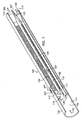
- FIG. 3 shows a longitudinal cross-section of the first alternative embodiment of the present invention.
- the apparatus comprises a catalytic reactor 100 comprised of a housing 102 having an entrance and an exit, and defining at least one aperture 107.
- a plate 115 is positioned within the housing 102 defining a first zone 105 and a second zone 106.
- the aperture 107 is in fluid communication with the second zone 106.
- At least two conduits 110 made from a heat conducting material and adapted for conducting a fluid are positioned within the housing 102.
- the conduits have an entrance 116, an exit 117 with an exit periphery 113, an interior surface 112, and an exterior surface 111.
- the conduits 110 are positioned within the housing 102 such that the conduits 110 penetrate plate 115 thereby having the conduit entrances 116 in fluid communication with the first zone 105 and the conduit exits within the second zone 106.
- a first fluid 120 entering first zone 105 must enter second zone 106, if at all, by exiting conduits 110.
- the conduit exit periphery 113 positions the conduits 110 relative to each other and the housing interior surface 114.
- the flow path 123 within housing 102 is defined by the conduit exterior surfaces 111.
- the flow path extends between the aperture 107 and the flow path exits, which are defined by the conduit exit peripheries 113.
- the flow path 123 can have numerous physical configurations that are application dependent. In general, the flow path must permit the diffusion of the entering second fluid 127 in a manner to ensure the second fluid 127 can enter all the passages containing catalyst downstream therefrom.
- FIG. 3 depicts a partitioned flow path.
- the flow path 123 allows for the second fluid 127 to disperse throughout housing 102.
- the flow path has been subdivided into a plurality of smaller passages. Partitioned means that the fluid is essentially confined to the smaller passages. Partitioning is accomplished by physical means, such as a solid barrier or by contact (close proximity) of surfaces. In this embodiment, the subdivision into a plurality of small passages is accomplished by contact, expanding the cross-section of the conduits 110 so that they touch.
- a catalyst 103 has been deposited on a portion of the conduit exterior surface 111. Catalyst can be deposited anywhere in the flow path. It is preferred that the catalyst be deposited downstream of aperture 107.
- FIG. 4 is a cross-sectional view of the housing 102 taken through aperture 107 looking downstream showing the definition of the flow path 123 by the conduit exterior surfaces 111 within housing 102.
- the cross-sections of the conduits 110 are sized to permit the fluid to easily flow around the conduit exterior surfaces 111.
- FIG. 5 which is a cross-sectional view of the housing 102 approximately mid-way between the aperture 107 and the flow path exits 125
- the conduit 110 cross-sections have been sized such that the conduit exterior surfaces covered with catalyst 103 touch, or nearly touch, one another or the housing interior surface 114.
- the sizing of the conduit 110 cross-sections in this manner effectively divides the flow path 123 into a plurality of passages.
- FIG. 6 shows an end view of the catalytic reactor 100 looking upstream from the discharge end of the catalytic reactor 100.
- the conduit exit peripheries 113 define the flow path exits 125 as well as assure the conduit exits 117 are interspersed with the flow path exits 125.
- the conduit exit peripheries 113 provide the structure which holds the conduits 110 in position by contacting the housing interior surface 114 within the housing 102.
- FIG. 7 shows a longitudinal cross-section of another embodiment of the present invention.
- This embodiment is the same as that depicted in FIG. 3 except that the flow path 123 is of a different configuration.
- the flow path is unpartitioned.
- the conduit cross-sections are sized to allow the second fluid 127 to flow around the conduits throughout the entire length of the flow channel 123.
- the flow path after the initial dispersion area can be partitioned, unpartitioned, or a combination.
- the conduit exit peripheries 113 define the flow path exits 125 as well as assure the conduit exits 117 are interspersed with the flow path exits 125.
- the conduit exit peripheries 113 provide the structure which holds the conduits 110 in position by contacting the housing interior surface 114 within the housing 102. While flares are shown, it is not required and the invention should not be considered so limited.
- FIG. 8 shows a longitudinal cross-section of another embodiment of the present invention. This embodiment is the same as that depicted in Figure 3 except that the flow path 123 is partitioned by a physical barrier.
- the conduit exterior surfaces are integrated into a structure resembling a monolith.
- the flow path 123 is still considered defined by the conduit exterior surfaces 111, and the catalyst 103 is considered deposited thereon.
- FIG. 9 shows a longitudinal cross-section of the embodiment depicted in FIG. 3 with a plenum 130 added upstream of the aperture 107 and in fluid communication therewith. If a plenum 130 is employed multiple apertures 107 are preferred. A plenum 130 can be incorporated into any of the previously discussed embodiments.
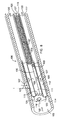
- FIG. 10 shows a longitudinal cross-section of another embodiment of the present invention very similar to that disclosed in FIG. 3 .
- the catalytic reactor 200 comprises a housing 202 having an exit, and defining at least one aperture 207.
- At least two conduits 210 made from a heat conducting material and adapted for conducting a fluid are positioned within the housing 202.
- the conduits have an entrance 216, an exit 217 with an exit periphery 213, an interior surface 212, and an exterior surface 211.
- the conduits 210 are positioned within the housing 202 such that the conduits 210 penetrate the housing thereby having the conduit exits within the housing 202 and the conduit entrances 216 opening to an area outside the housing 202.
- a first fluid 220 entering conduits 210 enters housing 202, if at all, by exiting conduits 210.
- the conduit exit periphery 213 positions the conduits 210 relative to each other and the housing interior surface 214.
- FIG. 10 depicts an unpartitioned flow path. This embodiment, however, has all the flexibility of the first embodiment. As with the first embodiment a plenum could also be incorporated.
- the catalytic reactor For application in a gas turbine, the catalytic reactor must be integrated into the gas turbine combustion system.
- the reactor housing is relieved of the need to contain high pressure.
- the fuel-rich fuel/air mixture advantageously should be uniformly mixed prior to delivery to the flow path. Mixing of fuel and air within the flow path is also feasible if the reactor is designed accordingly.
- Sufficient catalyst coating means sufficient loading, on a weight basis, as well as sufficient geometric surface area of catalyst. Insufficient loading will result in an insufficient number of catalytic reaction sites, and insufficient geometric surface area will result in insufficient total mass transfer from the gas-phase to the catalytic surface. In either case, insufficient catalyst means that O 2 conversions will be below the preferred levels.
- the required loading and the required geometric surface area will depend upon operating conditions (e.g. reactant temperature, pressure, velocity, composition) and catalyst activity, and can be determined by methods known in chemical engineering practice.
- the catalyst coating used in the present invention may have as an active ingredient precious metals, group VIII noble metals, base metals, metal oxides, or any combination thereof.
- precious metals group VIII noble metals, base metals, metal oxides, or any combination thereof.
- Elements such as zirconium, vanadium, chromium, manganese, copper, platinum, palladium, osmium, iridium, rhodium, cerium, lanthanum, other elements of the lanthanide series, cobalt, nickel, iron, and the like may be used.
- the catalyst may be applied directly to the substrate, or may be applied to an intermediate bond coat or washcoat composed of alumina, silica, zirconia, titania, magnesia, other refractory metal oxides, or any combination thereof.
- the catalyst-coated substrate may be fabricated from any of various high temperature materials.
- High temperature metal alloys are preferred, particularly alloys composed of iron, nickel, and/or cobalt, in combination with aluminum, chromium, and/or other alloying materials.
- High temperature nickel alloys are especially preferred.
- Other materials which may be used include ceramics, metal oxides, intermetallic materials, carbides, and nitrides.
- Metallic substrates are most preferred due to their excellent thermal conductivity, allowing effective backside cooling of the catalyst.
- Fuel types include hydrocarbons, hydrocarbon oxygenates, and blends thereof.
- Suitable gaseous fuels include natural gas, methane, and propane.
- Suitable liquid fuels include gasoline, kerosene, No. 1 heating oil, No. 2 heating oil, and conventional aviation turbine fuels such as Jet A, Jet B, JP-4, JP-5, JP-7, and JP-8.
- Jet A, Jet B, JP-4, JP-5, JP-7, and JP-8 "Hydrocarbon” not only refers to organic compounds, including conventional liquid and gaseous fuels, but also to gas streams containing fuel values in the form of compounds such as carbon monoxide, organic compounds, or partial oxidation products of carbon containing compounds. If the fuel is a liquid, it should be vaporized or atomized before mixing with air or while being mixed with air.
- a catalytic reactor similar to that illustrated in FIG. 9 was fabricated for dual air-source testing, with separate air flow controls for the flow path and the conduits.
- a single fuel source was employed.
- a plenum supplied the fuel-rich fuel/air mixture to the flow path through multiple apertures.
- the product stream exited the flow path via the interstitial space created by the conduit peripheries.
- the cooling air exited the conduits at this same axial location, and mixed with the product stream.
- the conduits specifically tubes, were 25.4 cm (10 inches) in length with an outside diameter of 0.478 cm (88 inches) and a material thickness of 0.025 cm (0.010 inches)
- One end of the tube was expanded at a constant angle of 4 degrees until the cross-section was increased about 30 percent, to a final inside diameter of 0.648 cm (0.255 inches)
- a flat segment was provided on the 0.648 cm (0.255-inch) diameter flared section of about 0.25 cm (0.1 inches) length.
- the housing was sized such that seven tubes could be accommodated and positioned therein by the flares.
- the tubes were inserted through the plate and brazed thereto to form a tight seal.
- a catalyst was deposited on approximately 21.6 cm (8.5 inches) of the exterior of the tubes.
- an alumina washcoat was first applied, with a loading of approximately 3.1 to 6.2 mg/cm 2 (20 to 40 mg/square-inch).
- Palladium catalyst was then applied to the washcoat, with a loading of approximately 1.5 to 2.3 mg/cm 2 (10 to 15 mg/square-inch). There was some variation in both washcoat and catalyst loading.
- the catalytic reactor was installed in a refractory-lined cylindrical pressure vessel to permit testing of the catalytic reactor at pressure.
- a fuel/air inlet pipe penetrated the vessel wall through a high-pressure fitting, and mated with a sealing fitting at the fuel/air inlet plenum of the catalytic reactor. Cooling air was supplied to the conduits by a separate line which entered the pressure vessel at its upstream end.
- the combustible gas mixture (the combined product stream and the cooling stream) entered a 1.26 cm (0.495-inch) inside-diameter extension tube, followed by a nozzle block that tapered down to a 0.953 cm (0.375-inch) inside-diameter at its exit.
- the total length from the conduit exits to the downstream end of the nozzle block was approximately 38 cm (15 inches) Immediately downstream of the nozzle block exit was a sudden expansion to a 7.6 (3-inch) diameter burnout zone for combustion completion.
- the catalytic reactor was operated at an inlet reference velocity of 76 m (250 ft)/s.
- the inlet reference velocity is defined as the velocity which would result inside the catalytic reactor housing without the conduits.
- the fuel flow rate was set to provide an overall 0.5 equivalence ratio in the fuel-lean fuel/air mixture downstream of the catalyst, giving an equivalence ratio of 5.0 for the fuel-rich fuel/air mixture.
- the cooling air was heated to 510°C (950 degrees F) at the catalytic reactor inlet.
- the fuel-rich fuel/air mixture entered at room temperature (nominally 16°C (60 degrees F)).
- the resulting overall adiabatic flame temperature in the downstream burn-out zone was approximately 1538°C (2800 degrees F).
- the maximum catalyst substrate temperature was measured to be below approximately 982°C (1800 degrees F), which is below the substrate and catalyst material failure point. Gas sampling from the downstream end of the flow path indicated that approximately 90 percent of the O 2 present in the fuel-rich fuel/air mixture was consumed prior to exiting the flow path.
Landscapes
- Engineering & Computer Science (AREA)
- Chemical & Material Sciences (AREA)
- Combustion & Propulsion (AREA)
- Mechanical Engineering (AREA)
- General Engineering & Computer Science (AREA)
- Chemical Kinetics & Catalysis (AREA)
- Exhaust Gas After Treatment (AREA)
- Fluidized-Bed Combustion And Resonant Combustion (AREA)
- Feeding, Discharge, Calcimining, Fusing, And Gas-Generation Devices (AREA)
- Gas Burners (AREA)
Claims (31)
- Verfahren zum Teiloxidieren eines Brennstoffs (33), umfassend:Mischen des Brennstoffs (33) mit einem ersten Fluidstrom (32) enthaltend Oxidationsmittel zur Erzeugung eines brennstoffreichen Brennstoff-/Oxidationsmittel-Gemisches (37);Kontaktieren des brennstoffreichen Brennstoff-/Oxidationsmittel-Gemisches (37) mit einem Katalysator (3) für das Oxidieren zumindest eines Teils des Brennstoffs (33) in dem brennstoffreichen Brennstoff-/Oxidationsmittel-Gemisch (37), wodurch ein Produktstrom (31) und Reaktionswärme (39) entsteht;Leiten mindestens eines Teils der Reaktionswärme (39) in einen Oxidationsmittel enthaltenden Kühlmittelstrom (30), wobei der Kühlmittelstrom (30) eine Strömungsgeschwindigkeit aufweist, die beim Mischen mit dem Produktstrom (31) zur Bildung eines brennstoffarmen Brennstoff-/Oxidationsmittel-Gemisches (38) ausreicht; undKontaktieren des Produktstroms (31) mit dem Kühlmittelstrom (30).
- Verfahren nach Anspruch 1, umfassend den weiteren Schritt des Mischens des Produktstroms (31) und des Kühlmittelstroms (30) zur Erzeugung eines brennstoffarmen Brennstoff-/Luft-Gemisches (38).
- Verfahren nach Anspruch 2, ferner umfassend die Schritte des Komprimierens eines Oxidationsmittel enthaltenden dritten Fluidstroms (36) und Trennen des ersten Fluidstroms (32) und des Kühlmittelstroms (30) vom dritten Fluidstrom (36).
- Verfahren nach Anspruch 3, umfassend den weiteren Schritt des Gasphasenverbrennens des brennstoffarmen Brennstoff-/Oxidationsmittel-Gemisches (38).
- Verfahren nach Anspruch 2, wobei der Produktstrom (31) in mehrere Ströme aufgeteilt und in den Kühlmittelstrom (30) verteilt wird.
- Verfahren nach Anspruch 2, wobei der Kühlmittelstrom (30) in mehrere Ströme aufgeteilt und in den Produktstrom (31) verteilt wird.
- Verfahren nach Anspruch 2, wobei der Produktstrom (31) und der Kühlmittelstrom (30) jeweils mehrere verteilte Ströme umfassen.
- Verfahren nach Anspruch 1, wobei der Produktstrom (31) und der Kühlmittelstrom (30) nach Kontaktierung eine stöchiometrische Grenzfläche mit einer stöchiometrischen Brenntemperatur unterhalb ca. 1816°C (3300 Grad F) erzeugen.
- Verfahren nach Anspruch 1, wobei die Reaktionswärme (39) durch rückseitigen Kontakt vom Katalysator (3) in das Fühlmittel (30) geleitet wird.
- Verfahren nach Anspruch 9, wobei der Brennstoff (33) einen Kohlenwasserstoff enthält.
- Verfahren nach Anspruch 1, wobei der Brennstoff (33) einen Kohlenwasserstoff enthält.
- Verfahren nach Anspruch 11, wobei der Brennstoff (33) in Verbindung mit dem Oxidationsmittel eine definierte reiche Flammbarkeitsgrenze aufweist und das brennstoffreiche Brennstoff-/Oxidationsmittel-Gemisch (37) ein Äquivalenzverhältnis aufweist, das größer ist als die reiche Flammbarkeitsgrenze.
- Verfahren nach Anspruch 12, umfassend den weiteren Schritt des Mischens des Produktstroms (31) und des Kühlmittelstroms (30) zur Erzeugung eines brennstoffarmen Brennstoff-/Luft-Gemisches (38).
- Verfahren nach Anspruch 13, umfassend den weiteren Schritt des Gasphasenverbrennens des brennstoffarmen Brennstoff-/Oxidationsmittel-Gemisches (38).
- Verfahren nach Anspruch 11, wobei der Brennstoff (33) in Verbindung mit dem Oxidationsmittel eine definierte reiche Flammbarkeitsgrenze aufweist und das brennstoffreiche Brennstoff-/Oxidationsmittel-Gemisch (37) ein Äquivalenzverhältnis aufweist, das niedriger ist als die reiche Flammbarkeitsgrenze.
- Verfahren nach Anspruch 1, wobei das brennstoffreiche Brennstoff-/Oxidationsmittel-Gemisch (37) ein Äquivalenzverhältnis von kleiner als 10 aufweist.
- Verfahren nach Anspruch 16, wobei das brennstoffreiche Brennstoff-/Oxidationsmittel-Gemisch (37) ein Äquivalenzverhältnis von kleiner als 5 aufweist.
- Verfahren nach Anspruch 17, wobei mehr als 50 Prozent des Oxidationsmittels in dem ersten Fluidstrom (32) in Gegenwart des Katalysators (3) reagieren.
- Verfahren nach Anspruch 18, wobei mehr als 50 Prozent der Reaktionswärme (39) zum Kühlmittelstrom (30) geleitet werden.
- Verfahren nach Anspruch 16, wobei mehr als 50 Prozent des Oxidationsmittels in dem ersten Fluidstrom (32) in Gegenwart des Katalysators (3) reagieren.
- Verfahren nach Anspruch 20, wobei mehr als 50 Prozent der Reaktionswärme (39) zum Kühlmittelstrom (30) geleitet werden.
- Katalytischer Reaktor (100, 200), umfassend:ein Gehäuse (102, 202) mit einem Ausgang, wobei das Gehäuse (102, 202) mindestens eine Öffnung (107, 207) definiert;mindestens zwei Leitungen (110, 210), die aus einem wärmeleitenden Material bestehen und zum Leiten eines ersten Fluids (120, 220) ausgebildet sind, wobei die Leitung (110, 210) einen Eingang (116, 216), einen Ausgang (117, 217) mit einem Umfang (113, 213) und eine Außenfläche (111, 211) aufweist, wobei die Leitungen (110, 210) in dem Gehäuse (102, 202) angeordnet sind, derart dass:die Leitungen (110, 210) durch das Gehäuse (102, 202) hindurch treten, wobei die Leitungsausgänge (117, 217) sich innerhalb des Gehäuses (102, 202) befinden, die Leitungsaußenflächen (111, 211) innerhalb des Gehäuses (102, 202) einen Strömungsweg (123, 223) definieren, die Leitungsausgangsumfänge (113, 213) mindestens einen Strömungwegausgang (125, 225) definieren, wobei die Leitungsausgänge (117, 217) und der Strömungswegausgang (125, 225) nahe beieinander angeordnet und verteilt sind, wobei der Strömungsweg (123, 223) in Fluidverbindung mit der Öffnung (107, 207) steht; undMittel, um mindestens einen Teil des Strömungweges (123, 223) katalytisch aktiv werden zu lassen.
- Katalytischer Reaktor (100) nach Anspruch 22,
wobei das Gehäuse (102) auch einen Eingang und eine Innenfläche (114) aufweist; wobei der katalytische Reaktor (100) auch eine Platte (115) aufweist, die eine erste Zone (105) und eine zweite Zone (106) ausbildend in dem Gehäuse (102) angeordnet ist;
wobei die Leitungen (110) derart in dem Gehäuse (102) angeordnet sind, dass:die Leitungen (110) durch die Platte (115) hindurch treten, wobei die Leitungsausgänge (117) in der zweiten Zone (106) liegen und die Leitungseingänge (116) in die erste Zone (105) münden,der Strömungsweg (123) durch die Leitungsaußenflächen (111) in der zweiten Zone (106) und die Gehäuseinnenfläche (114) in der zweiten Zone (106) definiert ist, und wobei das Mittel, durch das mindestens ein Teil des Strömungsweges (123) katalytisch aktiv wird, ein katalytisches Mittel (103) ist. - Katalytischer Reaktor (100, 200) nach Anspruch 22 oder 23, wobei der Strömungsweg (123, 223) nicht versperrt ist.
- Katalytischer Reaktor (100, 200) nach Anspruch 24, wobei die Leitung (110, 210) eine Innenfläche (112, 212) aufweist und das katalytische Mittel (103, 203) an mindestens einem Abschnitt mindestens einer der Außenflächen (111, 211) derart angeordnet ist, dass ein Wärmetauschverhältnis mit der Innenfläche (112, 212) besteht.
- Katalytischer Reaktor (100, 200) nach Anspruch 22 oder 23, wobei der Strömungsweg (123, 223) stromabwärts der Öffnung (107, 207) aus einer Vielzahl von Kanälen besteht.
- Katalytischer Reaktor (100, 200) nach Anspruch 26, wobei die Leitung (110, 210) eine Innenfläche (112, 212) aufweist und das katalytische Mittel (103, 203) an mindestens einem Abschnitt mindestens einer der Außenflächen (111, 211) derart angeordnet ist, dass ein Wärmetauschverhältnis mit der Innenfläche (112, 212) besteht.
- Katalytischer Reaktor (100) nach Anspruch 22 oder 23, ferner umfassend einen Zwischenraum (130), der stromaufwärts der Öffnung (107) in Fluidverbindung mit diesem angeordnet ist.
- Katalytischer Reaktor (100, 200) nach Anspruch 22 oder 23, wobei die Leitung (110, 210) eine Innenfläche (112, 212) aufweist und das katalytische Mittel (103, 203) an mindestens einem Abschnitt mindestens einer der Außenflächen (111, 211) derart angeordnet ist, dass ein Wärmetauschverhältnis mit der Innenfläche (112, 212) besteht.
- Katalytischer Reaktor (100, 200) nach Anspruch 29, wobei der Strömungsweg (123, 223) nicht versperrt ist.
- Katalytischer Reaktor (100, 200) nach Anspruch 29, wobei der Strömungsweg (123, 223) stromabwärts der Öffnung (107, 207) aus einer Vielzahl von Kanälen besteht.
Applications Claiming Priority (3)
| Application Number | Priority Date | Filing Date | Title |
|---|---|---|---|
| US09/527,708 US6358040B1 (en) | 2000-03-17 | 2000-03-17 | Method and apparatus for a fuel-rich catalytic reactor |
| US527708 | 2000-03-17 | ||
| PCT/US2001/040297 WO2001071252A1 (en) | 2000-03-17 | 2001-03-14 | Method and apparatus for a fuel-rich catalytic reactor |
Publications (3)
| Publication Number | Publication Date |
|---|---|
| EP1266176A1 EP1266176A1 (de) | 2002-12-18 |
| EP1266176A4 EP1266176A4 (de) | 2009-11-04 |
| EP1266176B1 true EP1266176B1 (de) | 2013-02-27 |
Family
ID=24102599
Family Applications (1)
| Application Number | Title | Priority Date | Filing Date |
|---|---|---|---|
| EP01959933A Expired - Lifetime EP1266176B1 (de) | 2000-03-17 | 2001-03-14 | Verfahren und vorrichtung für einen brennstoffreichen katalytischen reaktor |
Country Status (7)
| Country | Link |
|---|---|
| US (3) | US6358040B1 (de) |
| EP (1) | EP1266176B1 (de) |
| JP (1) | JP2003528283A (de) |
| AU (1) | AU2001281498A1 (de) |
| CA (1) | CA2403092C (de) |
| MX (1) | MXPA02009030A (de) |
| WO (1) | WO2001071252A1 (de) |
Families Citing this family (111)
| Publication number | Priority date | Publication date | Assignee | Title |
|---|---|---|---|---|
| US6358040B1 (en) * | 2000-03-17 | 2002-03-19 | Precision Combustion, Inc. | Method and apparatus for a fuel-rich catalytic reactor |
| US6250915B1 (en) * | 2000-03-29 | 2001-06-26 | The Boc Group, Inc. | Burner and combustion method for heating surfaces susceptible to oxidation or reduction |
| US6415608B1 (en) * | 2000-09-26 | 2002-07-09 | Siemens Westinghouse Power Corporation | Piloted rich-catalytic lean-burn hybrid combustor |
| US7121097B2 (en) | 2001-01-16 | 2006-10-17 | Catalytica Energy Systems, Inc. | Control strategy for flexible catalytic combustion system |
| US6718772B2 (en) | 2000-10-27 | 2004-04-13 | Catalytica Energy Systems, Inc. | Method of thermal NOx reduction in catalytic combustion systems |
| US6796129B2 (en) | 2001-08-29 | 2004-09-28 | Catalytica Energy Systems, Inc. | Design and control strategy for catalytic combustion system with a wide operating range |
| US6748745B2 (en) * | 2001-09-15 | 2004-06-15 | Precision Combustion, Inc. | Main burner, method and apparatus |
| US20030053939A1 (en) * | 2001-09-15 | 2003-03-20 | Smith Lance L. | Baffle plate for single flow channel reactors |
| US20030054300A1 (en) * | 2001-09-15 | 2003-03-20 | Castaldi Marco J. | Apparatus having similar interstitial passages |
| US20030072708A1 (en) * | 2001-09-19 | 2003-04-17 | Smith Lance L. | Method for dual-fuel operation of a fuel-rich catalytic reactor |
| CH695793A5 (de) * | 2001-10-01 | 2006-08-31 | Alstom Technology Ltd | Verbrennungsverfahren, insbesondere für Verfahren zur Erzeugung von elektrischem Strom und/oder von Wärme. |
| US7117674B2 (en) * | 2002-04-10 | 2006-10-10 | The Boeing Company | Catalytic combustor and method for substantially eliminating various emissions |
| US6966186B2 (en) * | 2002-05-01 | 2005-11-22 | Siemens Westinghouse Power Corporation | Non-catalytic combustor for reducing NOx emissions |
| AU2003240374A1 (en) | 2002-08-30 | 2004-03-19 | Alstom Technology Ltd | Hybrid burner and corresponding operating method |
| CN100489397C (zh) * | 2002-08-30 | 2009-05-20 | 阿尔斯托姆科技有限公司 | 用于使燃料氧化剂混合物燃烧的方法和装置 |
| AU2003232574A1 (en) * | 2002-08-30 | 2004-03-19 | Alstom Technology Ltd | Method and device for mixing fluid flows |
| US6775989B2 (en) * | 2002-09-13 | 2004-08-17 | Siemens Westinghouse Power Corporation | Catalyst support plate assembly and related methods for catalytic combustion |
| US20040255588A1 (en) * | 2002-12-11 | 2004-12-23 | Kare Lundberg | Catalytic preburner and associated methods of operation |
| US6829896B2 (en) | 2002-12-13 | 2004-12-14 | Siemens Westinghouse Power Corporation | Catalytic oxidation module for a gas turbine engine |
| US7617682B2 (en) * | 2002-12-13 | 2009-11-17 | Siemens Energy, Inc. | Catalytic oxidation element for a gas turbine engine |
| BRPI0406806A (pt) * | 2003-01-17 | 2005-12-27 | Catalytica Energy Sys Inc | Sistema e método de controle dinâmico para multicombustor catalìtico para motor de turbina a gás |
| US7117676B2 (en) * | 2003-03-26 | 2006-10-10 | United Technologies Corporation | Apparatus for mixing fluids |
| US7007486B2 (en) * | 2003-03-26 | 2006-03-07 | The Boeing Company | Apparatus and method for selecting a flow mixture |
| WO2004094909A1 (de) * | 2003-04-24 | 2004-11-04 | Alstom Technology Ltd | Verfahren und vorrichtung zum betreiben eines brenners einer wärmekraftmaschine, insbesondere einer gasturbinenanlage |
| DE10329162A1 (de) * | 2003-06-27 | 2005-01-13 | Alstom Technology Ltd | Katalytischer Reaktor und zugehöriges Betriebsverfahren |
| WO2005026675A2 (en) * | 2003-09-05 | 2005-03-24 | Catalytica Energy Systems, Inc. | Catalyst module overheating detection and methods of response |
| US20050105666A1 (en) * | 2003-09-15 | 2005-05-19 | Saed Mirzadeh | Production of thorium-229 |
| US7278265B2 (en) * | 2003-09-26 | 2007-10-09 | Siemens Power Generation, Inc. | Catalytic combustors |
| US7469544B2 (en) * | 2003-10-10 | 2008-12-30 | Pratt & Whitney Rocketdyne | Method and apparatus for injecting a fuel into a combustor assembly |
| US7017329B2 (en) | 2003-10-10 | 2006-03-28 | United Technologies Corporation | Method and apparatus for mixing substances |
| US20050126755A1 (en) * | 2003-10-31 | 2005-06-16 | Berry Jonathan D. | Method and apparatus for improved flame stabilization |
| US7140184B2 (en) * | 2003-12-05 | 2006-11-28 | United Technologies Corporation | Fuel injection method and apparatus for a combustor |
| JP3903195B2 (ja) * | 2003-12-16 | 2007-04-11 | 川崎重工業株式会社 | 燃料ノズル |
| US7111463B2 (en) * | 2004-01-23 | 2006-09-26 | Pratt & Whitney Rocketdyne Inc. | Combustion wave ignition for combustors |
| US7127899B2 (en) * | 2004-02-26 | 2006-10-31 | United Technologies Corporation | Non-swirl dry low NOx (DLN) combustor |
| US7691338B2 (en) * | 2004-03-10 | 2010-04-06 | Siemens Energy, Inc. | Two stage catalytic combustor |
| CA2561255A1 (en) * | 2004-03-30 | 2005-10-13 | Alstom Technology Ltd. | Device and method for flame stabilization in a burner |
| EP1738109A1 (de) * | 2004-03-31 | 2007-01-03 | Alstom Technology Ltd | Katalytischer reaktor und verfahren zur verbrennung von brennstoff-luft-gemischen mittels eines katalytischen reaktors |
| EP1614963A1 (de) | 2004-07-09 | 2006-01-11 | Siemens Aktiengesellschaft | Verfahren und Vormischverbrennungssystem |
| US7506516B2 (en) | 2004-08-13 | 2009-03-24 | Siemens Energy, Inc. | Concentric catalytic combustor |
| US7509807B2 (en) * | 2004-08-13 | 2009-03-31 | Siemens Energy, Inc. | Concentric catalytic combustor |
| US7469543B2 (en) * | 2004-09-30 | 2008-12-30 | United Technologies Corporation | Rich catalytic injection |
| US7444820B2 (en) | 2004-10-20 | 2008-11-04 | United Technologies Corporation | Method and system for rich-lean catalytic combustion |
| US20060218932A1 (en) * | 2004-11-10 | 2006-10-05 | Pfefferle William C | Fuel injector |
| US20060191269A1 (en) * | 2005-02-25 | 2006-08-31 | Smith Lance L | Catalytic fuel-air injector with bluff-body flame stabilization |
| JP2008534896A (ja) * | 2005-03-23 | 2008-08-28 | アルストム テクノロジー リミテッド | 前混合バーナにおいて水素を燃焼する方法と装置 |
| US7594400B2 (en) * | 2005-04-07 | 2009-09-29 | Siemens Energy, Inc. | Catalytic oxidation module for a gas turbine engine |
| US8196848B2 (en) * | 2005-04-29 | 2012-06-12 | Pratt & Whitney Rocketdyne, Inc. | Gasifier injector |
| US7874350B2 (en) * | 2005-05-23 | 2011-01-25 | Precision Combustion, Inc. | Reducing the energy requirements for the production of heavy oil |
| US7665525B2 (en) * | 2005-05-23 | 2010-02-23 | Precision Combustion, Inc. | Reducing the energy requirements for the production of heavy oil |
| US7537646B2 (en) * | 2005-10-11 | 2009-05-26 | United Technologies Corporation | Fuel system and method of reducing emission |
| US7521028B2 (en) | 2005-10-27 | 2009-04-21 | Precision Combustion, Inc. | Catalytic reactor for low-Btu fuels |
| US20070130956A1 (en) * | 2005-12-08 | 2007-06-14 | Chen Alexander G | Rich catalytic clean burn for liquid fuel with fuel stabilization unit |
| DE102005061486B4 (de) | 2005-12-22 | 2018-07-12 | Ansaldo Energia Switzerland AG | Verfahren zum Betreiben einer Brennkammer einer Gasturbine |
| US8167036B2 (en) | 2006-01-03 | 2012-05-01 | Precision Combustion, Inc. | Method for in-situ combustion of in-place oils |
| US8091625B2 (en) | 2006-02-21 | 2012-01-10 | World Energy Systems Incorporated | Method for producing viscous hydrocarbon using steam and carbon dioxide |
| US20070237692A1 (en) * | 2006-04-10 | 2007-10-11 | United Technologies Corporation | Catalytic reactor with tube inserts |
| US7727495B2 (en) * | 2006-04-10 | 2010-06-01 | United Technologies Corporation | Catalytic reactor with swirl |
| US20080173021A1 (en) * | 2006-04-17 | 2008-07-24 | Pfefferle William C | Method for improved efficiency for IGCC |
| US7712528B2 (en) * | 2006-10-09 | 2010-05-11 | World Energy Systems, Inc. | Process for dispersing nanocatalysts into petroleum-bearing formations |
| US7770646B2 (en) | 2006-10-09 | 2010-08-10 | World Energy Systems, Inc. | System, method and apparatus for hydrogen-oxygen burner in downhole steam generator |
| US8256221B2 (en) | 2007-04-05 | 2012-09-04 | Siemens Energy, Inc. | Concentric tube support assembly |
| US8397509B2 (en) * | 2007-06-06 | 2013-03-19 | Herng Shinn Hwang | Catalytic engine |
| US20090251989A1 (en) * | 2007-06-26 | 2009-10-08 | Pfefferle William C | Streamlined flow mixer |
| US8061120B2 (en) | 2007-07-30 | 2011-11-22 | Herng Shinn Hwang | Catalytic EGR oxidizer for IC engines and gas turbines |
| US7980082B2 (en) * | 2007-08-01 | 2011-07-19 | General Electric Company | Wobbe control and enhanced operability through in-line fuel reforming |
| US8215117B2 (en) * | 2007-10-15 | 2012-07-10 | United Technologies Corporation | Staging for rich catalytic combustion |
| US20090139235A1 (en) * | 2007-12-03 | 2009-06-04 | General Electric Company | Catalytically Stabilized Gas Turbine Combustor |
| US8864491B1 (en) | 2007-12-12 | 2014-10-21 | Precision Combustion, Inc. | Direct injection method and apparatus for low NOx combustion of high hydrogen fuels |
| US8091636B2 (en) * | 2008-04-30 | 2012-01-10 | World Energy Systems Incorporated | Method for increasing the recovery of hydrocarbons |
| US7928596B2 (en) | 2008-10-06 | 2011-04-19 | General Electric Company | Systems and methods for the utilization of energy generated by a powered vehicle |
| CA2741861C (en) * | 2008-11-06 | 2013-08-27 | American Shale Oil, Llc | Heater and method for recovering hydrocarbons from underground deposits |
| US20100175386A1 (en) * | 2009-01-09 | 2010-07-15 | General Electric Company | Premixed partial oxidation syngas generation and gas turbine system |
| US20100175379A1 (en) * | 2009-01-09 | 2010-07-15 | General Electric Company | Pre-mix catalytic partial oxidation fuel reformer for staged and reheat gas turbine systems |
| US8316647B2 (en) * | 2009-01-19 | 2012-11-27 | General Electric Company | System and method employing catalytic reactor coatings |
| US7963328B2 (en) * | 2009-03-30 | 2011-06-21 | Gas Technology Institute | Process and apparatus for release and recovery of methane from methane hydrates |
| WO2011008998A2 (en) | 2009-07-17 | 2011-01-20 | World Energy Systems Incorporated | Method and apparatus for a downhole gas generator |
| US8739550B2 (en) * | 2009-09-30 | 2014-06-03 | Precision Combustion, Inc. | Two stage combustor with reformer |
| MX2012010413A (es) | 2010-03-08 | 2013-04-11 | World Energy Systems Inc | Un generador de vapor situado en el fondo de la perforacion y metodo de uso. |
| US8252251B2 (en) * | 2010-03-30 | 2012-08-28 | General Electric Company | Fluid cooled reformer and method for cooling a reformer |
| US8800289B2 (en) | 2010-09-08 | 2014-08-12 | General Electric Company | Apparatus and method for mixing fuel in a gas turbine nozzle |
| US20120103604A1 (en) * | 2010-10-29 | 2012-05-03 | General Electric Company | Subsurface heating device |
| US9010083B2 (en) | 2011-02-03 | 2015-04-21 | General Electric Company | Apparatus for mixing fuel in a gas turbine |
| US9388985B2 (en) * | 2011-07-29 | 2016-07-12 | General Electric Company | Premixing apparatus for gas turbine system |
| US9506654B2 (en) | 2011-08-19 | 2016-11-29 | General Electric Company | System and method for reducing combustion dynamics in a combustor |
| US8984887B2 (en) | 2011-09-25 | 2015-03-24 | General Electric Company | Combustor and method for supplying fuel to a combustor |
| US8801428B2 (en) | 2011-10-04 | 2014-08-12 | General Electric Company | Combustor and method for supplying fuel to a combustor |
| US8550809B2 (en) | 2011-10-20 | 2013-10-08 | General Electric Company | Combustor and method for conditioning flow through a combustor |
| US9188335B2 (en) | 2011-10-26 | 2015-11-17 | General Electric Company | System and method for reducing combustion dynamics and NOx in a combustor |
| US8894407B2 (en) | 2011-11-11 | 2014-11-25 | General Electric Company | Combustor and method for supplying fuel to a combustor |
| US9033699B2 (en) | 2011-11-11 | 2015-05-19 | General Electric Company | Combustor |
| US9004912B2 (en) | 2011-11-11 | 2015-04-14 | General Electric Company | Combustor and method for supplying fuel to a combustor |
| US9322557B2 (en) | 2012-01-05 | 2016-04-26 | General Electric Company | Combustor and method for distributing fuel in the combustor |
| US9341376B2 (en) | 2012-02-20 | 2016-05-17 | General Electric Company | Combustor and method for supplying fuel to a combustor |
| US9052112B2 (en) | 2012-02-27 | 2015-06-09 | General Electric Company | Combustor and method for purging a combustor |
| US8511086B1 (en) | 2012-03-01 | 2013-08-20 | General Electric Company | System and method for reducing combustion dynamics in a combustor |
| US9121612B2 (en) | 2012-03-01 | 2015-09-01 | General Electric Company | System and method for reducing combustion dynamics in a combustor |
| US10865709B2 (en) | 2012-05-23 | 2020-12-15 | Herng Shinn Hwang | Flex-fuel hydrogen reformer for IC engines and gas turbines |
| US9212822B2 (en) | 2012-05-30 | 2015-12-15 | General Electric Company | Fuel injection assembly for use in turbine engines and method of assembling same |
| US9249734B2 (en) | 2012-07-10 | 2016-02-02 | General Electric Company | Combustor |
| US8904798B2 (en) | 2012-07-31 | 2014-12-09 | General Electric Company | Combustor |
| US9291082B2 (en) | 2012-09-26 | 2016-03-22 | General Electric Company | System and method of a catalytic reactor having multiple sacrificial coatings |
| US9353950B2 (en) | 2012-12-10 | 2016-05-31 | General Electric Company | System for reducing combustion dynamics and NOx in a combustor |
| PL2811228T3 (pl) * | 2013-06-07 | 2020-01-31 | Haldor Topsøe A/S | Palnik |
| US9273868B2 (en) | 2013-08-06 | 2016-03-01 | General Electric Company | System for supporting bundled tube segments within a combustor |
| US9371776B2 (en) * | 2013-08-20 | 2016-06-21 | Darren Levine | Dual flow air injection intraturbine engine and method of operating same |
| US9500370B2 (en) | 2013-12-20 | 2016-11-22 | General Electric Company | Apparatus for mixing fuel in a gas turbine nozzle |
| US10273790B2 (en) | 2014-01-14 | 2019-04-30 | Precision Combustion, Inc. | System and method of producing oil |
| US10145561B2 (en) | 2016-09-06 | 2018-12-04 | General Electric Company | Fuel nozzle assembly with resonator |
| US10626790B2 (en) | 2016-11-16 | 2020-04-21 | Herng Shinn Hwang | Catalytic biogas combined heat and power generator |
| JP6806618B2 (ja) | 2017-04-10 | 2021-01-06 | 三菱重工業株式会社 | ラムジェットエンジンの再生冷却器及びその製造方法 |
Family Cites Families (9)
| Publication number | Priority date | Publication date | Assignee | Title |
|---|---|---|---|---|
| US2805229A (en) * | 1953-08-06 | 1957-09-03 | Floyd J Metzger | Catalytic oxidation of ethylene |
| DE1268596B (de) * | 1965-10-06 | 1968-05-22 | Rolf Manteufel | Vorrichtung zum Stoff- und/oder Waermeaustausch und zur Mischung von gasfoermigen und/oder fluessigen Medien bzw. festen Stoffteilchen |
| DE2811273C2 (de) | 1978-03-15 | 1980-01-03 | Siemens Ag, 1000 Berlin Und 8000 Muenchen | Vergasungsbrenner |
| US4354821A (en) | 1980-05-27 | 1982-10-19 | The United States Of America As Represented By The United States Environmental Protection Agency | Multiple stage catalytic combustion process and system |
| US4459126A (en) | 1982-05-24 | 1984-07-10 | United States Of America As Represented By The Administrator Of The Environmental Protection Agency | Catalytic combustion process and system with wall heat loss control |
| US5235804A (en) | 1991-05-15 | 1993-08-17 | United Technologies Corporation | Method and system for combusting hydrocarbon fuels with low pollutant emissions by controllably extracting heat from the catalytic oxidation stage |
| US5326252A (en) | 1991-09-04 | 1994-07-05 | Thomas Tonon | Catalytic combustion |
| US6174159B1 (en) * | 1999-03-18 | 2001-01-16 | Precision Combustion, Inc. | Method and apparatus for a catalytic firebox reactor |
| US6358040B1 (en) * | 2000-03-17 | 2002-03-19 | Precision Combustion, Inc. | Method and apparatus for a fuel-rich catalytic reactor |
-
2000
- 2000-03-17 US US09/527,708 patent/US6358040B1/en not_active Expired - Lifetime
-
2001
- 2001-03-14 WO PCT/US2001/040297 patent/WO2001071252A1/en not_active Ceased
- 2001-03-14 CA CA002403092A patent/CA2403092C/en not_active Expired - Lifetime
- 2001-03-14 MX MXPA02009030A patent/MXPA02009030A/es active IP Right Grant
- 2001-03-14 JP JP2001569200A patent/JP2003528283A/ja active Pending
- 2001-03-14 AU AU2001281498A patent/AU2001281498A1/en not_active Abandoned
- 2001-03-14 EP EP01959933A patent/EP1266176B1/de not_active Expired - Lifetime
- 2001-07-20 US US09/909,517 patent/US6394791B2/en not_active Expired - Lifetime
-
2002
- 2002-05-06 US US10/139,996 patent/US6752623B2/en not_active Expired - Lifetime
Also Published As
| Publication number | Publication date |
|---|---|
| MXPA02009030A (es) | 2003-03-10 |
| EP1266176A1 (de) | 2002-12-18 |
| US6358040B1 (en) | 2002-03-19 |
| WO2001071252A1 (en) | 2001-09-27 |
| JP2003528283A (ja) | 2003-09-24 |
| US20020197578A1 (en) | 2002-12-26 |
| CA2403092C (en) | 2008-08-26 |
| AU2001281498A1 (en) | 2001-10-03 |
| US20010046650A1 (en) | 2001-11-29 |
| EP1266176A4 (de) | 2009-11-04 |
| US6394791B2 (en) | 2002-05-28 |
| CA2403092A1 (en) | 2001-09-27 |
| US6752623B2 (en) | 2004-06-22 |
Similar Documents
| Publication | Publication Date | Title |
|---|---|---|
| US6358040B1 (en) | Method and apparatus for a fuel-rich catalytic reactor | |
| US6174159B1 (en) | Method and apparatus for a catalytic firebox reactor | |
| EP1844844B1 (de) | Katalytischer Reaktor | |
| US5720609A (en) | Catalytic method | |
| US7594394B2 (en) | Catalytic reactor and method for the combustion of fuel-air mixtures by means of a catalytic reactor | |
| CN101687166B (zh) | 紧凑型燃料处理器 | |
| US7467942B2 (en) | Device and method for flame stabilization in a burner | |
| US7610761B2 (en) | Method and device for the combustion of hydrogen in a premix burner | |
| US8215117B2 (en) | Staging for rich catalytic combustion | |
| US20060096297A1 (en) | Method and apparatus for operating a burner of a heat engine, in particular of a gas turbine installation | |
| CA2459986C (en) | Main burner, method and apparatus | |
| JP2006118854A (ja) | リッチ−リーン触媒燃焼のための方法及びシステム | |
| US20020015931A1 (en) | Conduit positioner | |
| EP1844845A2 (de) | Katalytischer Reaktor mit einem statischen Mischer | |
| Ahn | Catalytic combustion of gas turbines: process modelling and kinetic study of iso-octane oxidation | |
| US20030072708A1 (en) | Method for dual-fuel operation of a fuel-rich catalytic reactor | |
| EP1269076B1 (de) | Verfahren und vorrichtung für einen katalytischen feuerungsreaktor | |
| WO1992016792A1 (en) | Apparatus and method for combustion within porous matrix elements | |
| JPH07243325A (ja) | 触媒方法 |
Legal Events
| Date | Code | Title | Description |
|---|---|---|---|
| PUAI | Public reference made under article 153(3) epc to a published international application that has entered the european phase |
Free format text: ORIGINAL CODE: 0009012 |
|
| 17P | Request for examination filed |
Effective date: 20021001 |
|
| AK | Designated contracting states |
Kind code of ref document: A1 Designated state(s): AT BE CH CY DE DK ES FI FR GB GR IE IT LI LU MC NL PT SE TR |
|
| AX | Request for extension of the european patent |
Free format text: AL;LT;LV;MK;RO;SI |
|
| A4 | Supplementary search report drawn up and despatched |
Effective date: 20091007 |
|
| 17Q | First examination report despatched |
Effective date: 20100416 |
|
| REG | Reference to a national code |
Ref country code: DE Ref legal event code: R079 Ref document number: 60147703 Country of ref document: DE Free format text: PREVIOUS MAIN CLASS: F23D0014180000 Ipc: F23C0006040000 |
|
| GRAC | Information related to communication of intention to grant a patent modified |
Free format text: ORIGINAL CODE: EPIDOSCIGR1 |
|
| GRAP | Despatch of communication of intention to grant a patent |
Free format text: ORIGINAL CODE: EPIDOSNIGR1 |
|
| RIC1 | Information provided on ipc code assigned before grant |
Ipc: F23C 6/04 20060101AFI20120904BHEP Ipc: F23R 3/40 20060101ALI20120904BHEP Ipc: F23R 3/34 20060101ALI20120904BHEP Ipc: F23C 13/00 20060101ALI20120904BHEP |
|
| GRAS | Grant fee paid |
Free format text: ORIGINAL CODE: EPIDOSNIGR3 |
|
| GRAA | (expected) grant |
Free format text: ORIGINAL CODE: 0009210 |
|
| AK | Designated contracting states |
Kind code of ref document: B1 Designated state(s): AT BE CH CY DE DK ES FI FR GB GR IE IT LI LU MC NL PT SE TR |
|
| REG | Reference to a national code |
Ref country code: GB Ref legal event code: FG4D |
|
| REG | Reference to a national code |
Ref country code: CH Ref legal event code: EP |
|
| REG | Reference to a national code |
Ref country code: CH Ref legal event code: NV Representative=s name: ING. MARCO ZARDI C/O M. ZARDI AND CO. S.A., CH Ref country code: AT Ref legal event code: REF Ref document number: 598712 Country of ref document: AT Kind code of ref document: T Effective date: 20130315 |
|
| REG | Reference to a national code |
Ref country code: IE Ref legal event code: FG4D |
|
| REG | Reference to a national code |
Ref country code: DE Ref legal event code: R096 Ref document number: 60147703 Country of ref document: DE Effective date: 20130425 |
|
| REG | Reference to a national code |
Ref country code: AT Ref legal event code: MK05 Ref document number: 598712 Country of ref document: AT Kind code of ref document: T Effective date: 20130227 |
|
| PG25 | Lapsed in a contracting state [announced via postgrant information from national office to epo] |
Ref country code: SE Free format text: LAPSE BECAUSE OF FAILURE TO SUBMIT A TRANSLATION OF THE DESCRIPTION OR TO PAY THE FEE WITHIN THE PRESCRIBED TIME-LIMIT Effective date: 20130227 Ref country code: AT Free format text: LAPSE BECAUSE OF FAILURE TO SUBMIT A TRANSLATION OF THE DESCRIPTION OR TO PAY THE FEE WITHIN THE PRESCRIBED TIME-LIMIT Effective date: 20130227 Ref country code: ES Free format text: LAPSE BECAUSE OF FAILURE TO SUBMIT A TRANSLATION OF THE DESCRIPTION OR TO PAY THE FEE WITHIN THE PRESCRIBED TIME-LIMIT Effective date: 20130607 |
|
| REG | Reference to a national code |
Ref country code: NL Ref legal event code: VDEP Effective date: 20130227 |
|
| PG25 | Lapsed in a contracting state [announced via postgrant information from national office to epo] |
Ref country code: GR Free format text: LAPSE BECAUSE OF FAILURE TO SUBMIT A TRANSLATION OF THE DESCRIPTION OR TO PAY THE FEE WITHIN THE PRESCRIBED TIME-LIMIT Effective date: 20130528 Ref country code: PT Free format text: LAPSE BECAUSE OF FAILURE TO SUBMIT A TRANSLATION OF THE DESCRIPTION OR TO PAY THE FEE WITHIN THE PRESCRIBED TIME-LIMIT Effective date: 20130627 Ref country code: BE Free format text: LAPSE BECAUSE OF FAILURE TO SUBMIT A TRANSLATION OF THE DESCRIPTION OR TO PAY THE FEE WITHIN THE PRESCRIBED TIME-LIMIT Effective date: 20130227 Ref country code: FI Free format text: LAPSE BECAUSE OF FAILURE TO SUBMIT A TRANSLATION OF THE DESCRIPTION OR TO PAY THE FEE WITHIN THE PRESCRIBED TIME-LIMIT Effective date: 20130227 |
|
| PG25 | Lapsed in a contracting state [announced via postgrant information from national office to epo] |
Ref country code: MC Free format text: LAPSE BECAUSE OF NON-PAYMENT OF DUE FEES Effective date: 20130331 Ref country code: DK Free format text: LAPSE BECAUSE OF FAILURE TO SUBMIT A TRANSLATION OF THE DESCRIPTION OR TO PAY THE FEE WITHIN THE PRESCRIBED TIME-LIMIT Effective date: 20130227 Ref country code: NL Free format text: LAPSE BECAUSE OF FAILURE TO SUBMIT A TRANSLATION OF THE DESCRIPTION OR TO PAY THE FEE WITHIN THE PRESCRIBED TIME-LIMIT Effective date: 20130227 |
|
| PG25 | Lapsed in a contracting state [announced via postgrant information from national office to epo] |
Ref country code: CY Free format text: LAPSE BECAUSE OF FAILURE TO SUBMIT A TRANSLATION OF THE DESCRIPTION OR TO PAY THE FEE WITHIN THE PRESCRIBED TIME-LIMIT Effective date: 20130227 |
|
| PG25 | Lapsed in a contracting state [announced via postgrant information from national office to epo] |
Ref country code: IT Free format text: LAPSE BECAUSE OF FAILURE TO SUBMIT A TRANSLATION OF THE DESCRIPTION OR TO PAY THE FEE WITHIN THE PRESCRIBED TIME-LIMIT Effective date: 20130227 |
|
| REG | Reference to a national code |
Ref country code: IE Ref legal event code: MM4A |
|
| PLBE | No opposition filed within time limit |
Free format text: ORIGINAL CODE: 0009261 |
|
| STAA | Information on the status of an ep patent application or granted ep patent |
Free format text: STATUS: NO OPPOSITION FILED WITHIN TIME LIMIT |
|
| PG25 | Lapsed in a contracting state [announced via postgrant information from national office to epo] |
Ref country code: IE Free format text: LAPSE BECAUSE OF NON-PAYMENT OF DUE FEES Effective date: 20130314 |
|
| 26N | No opposition filed |
Effective date: 20131128 |
|
| REG | Reference to a national code |
Ref country code: DE Ref legal event code: R097 Ref document number: 60147703 Country of ref document: DE Effective date: 20131128 |
|
| PGFP | Annual fee paid to national office [announced via postgrant information from national office to epo] |
Ref country code: CH Payment date: 20150319 Year of fee payment: 15 |
|
| PGFP | Annual fee paid to national office [announced via postgrant information from national office to epo] |
Ref country code: GB Payment date: 20150319 Year of fee payment: 15 |
|
| PG25 | Lapsed in a contracting state [announced via postgrant information from national office to epo] |
Ref country code: TR Free format text: LAPSE BECAUSE OF FAILURE TO SUBMIT A TRANSLATION OF THE DESCRIPTION OR TO PAY THE FEE WITHIN THE PRESCRIBED TIME-LIMIT Effective date: 20130227 |
|
| PG25 | Lapsed in a contracting state [announced via postgrant information from national office to epo] |
Ref country code: LU Free format text: LAPSE BECAUSE OF NON-PAYMENT OF DUE FEES Effective date: 20130314 |
|
| PG25 | Lapsed in a contracting state [announced via postgrant information from national office to epo] |
Ref country code: FR Free format text: LAPSE BECAUSE OF NON-PAYMENT OF DUE FEES Effective date: 20130331 |
|
| REG | Reference to a national code |
Ref country code: CH Ref legal event code: PL |
|
| GBPC | Gb: european patent ceased through non-payment of renewal fee |
Effective date: 20160314 |
|
| PG25 | Lapsed in a contracting state [announced via postgrant information from national office to epo] |
Ref country code: CH Free format text: LAPSE BECAUSE OF NON-PAYMENT OF DUE FEES Effective date: 20160331 Ref country code: LI Free format text: LAPSE BECAUSE OF NON-PAYMENT OF DUE FEES Effective date: 20160331 Ref country code: GB Free format text: LAPSE BECAUSE OF NON-PAYMENT OF DUE FEES Effective date: 20160314 |
|
| PGFP | Annual fee paid to national office [announced via postgrant information from national office to epo] |
Ref country code: DE Payment date: 20180322 Year of fee payment: 18 |
|
| REG | Reference to a national code |
Ref country code: DE Ref legal event code: R119 Ref document number: 60147703 Country of ref document: DE |
|
| PG25 | Lapsed in a contracting state [announced via postgrant information from national office to epo] |
Ref country code: DE Free format text: LAPSE BECAUSE OF NON-PAYMENT OF DUE FEES Effective date: 20191001 |