EP1266473B1 - Appareil et procede de commutation spectrale selective - Google Patents
Appareil et procede de commutation spectrale selective Download PDFInfo
- Publication number
- EP1266473B1 EP1266473B1 EP01926304A EP01926304A EP1266473B1 EP 1266473 B1 EP1266473 B1 EP 1266473B1 EP 01926304 A EP01926304 A EP 01926304A EP 01926304 A EP01926304 A EP 01926304A EP 1266473 B1 EP1266473 B1 EP 1266473B1
- Authority
- EP
- European Patent Office
- Prior art keywords
- phase control
- channels
- unit
- channel
- demultiplexing
- Prior art date
- Legal status (The legal status is an assumption and is not a legal conclusion. Google has not performed a legal analysis and makes no representation as to the accuracy of the status listed.)
- Expired - Lifetime
Links
- 238000000034 method Methods 0.000 title claims abstract description 20
- 230000003287 optical effect Effects 0.000 claims abstract description 44
- 230000005540 biological transmission Effects 0.000 claims abstract description 7
- 101100290389 Schizosaccharomyces pombe (strain 972 / ATCC 24843) ceg1 gene Proteins 0.000 claims description 4
- 238000012545 processing Methods 0.000 description 4
- VYPSYNLAJGMNEJ-UHFFFAOYSA-N Silicium dioxide Chemical compound O=[Si]=O VYPSYNLAJGMNEJ-UHFFFAOYSA-N 0.000 description 2
- 238000001914 filtration Methods 0.000 description 2
- 238000003384 imaging method Methods 0.000 description 2
- 238000011835 investigation Methods 0.000 description 2
- 238000004519 manufacturing process Methods 0.000 description 2
- 239000000463 material Substances 0.000 description 2
- 229910052681 coesite Inorganic materials 0.000 description 1
- 238000004891 communication Methods 0.000 description 1
- 238000012937 correction Methods 0.000 description 1
- 229910052906 cristobalite Inorganic materials 0.000 description 1
- 230000001419 dependent effect Effects 0.000 description 1
- 230000000694 effects Effects 0.000 description 1
- 230000005684 electric field Effects 0.000 description 1
- 239000000835 fiber Substances 0.000 description 1
- 239000000377 silicon dioxide Substances 0.000 description 1
- 230000003595 spectral effect Effects 0.000 description 1
- 229910052682 stishovite Inorganic materials 0.000 description 1
- 229910052905 tridymite Inorganic materials 0.000 description 1
- 238000009966 trimming Methods 0.000 description 1
Images


Classifications
-
- H—ELECTRICITY
- H04—ELECTRIC COMMUNICATION TECHNIQUE
- H04J—MULTIPLEX COMMUNICATION
- H04J14/00—Optical multiplex systems
- H04J14/02—Wavelength-division multiplex systems
- H04J14/0201—Add-and-drop multiplexing
- H04J14/0202—Arrangements therefor
- H04J14/0213—Groups of channels or wave bands arrangements
-
- G—PHYSICS
- G02—OPTICS
- G02F—OPTICAL DEVICES OR ARRANGEMENTS FOR THE CONTROL OF LIGHT BY MODIFICATION OF THE OPTICAL PROPERTIES OF THE MEDIA OF THE ELEMENTS INVOLVED THEREIN; NON-LINEAR OPTICS; FREQUENCY-CHANGING OF LIGHT; OPTICAL LOGIC ELEMENTS; OPTICAL ANALOGUE/DIGITAL CONVERTERS
- G02F1/00—Devices or arrangements for the control of the intensity, colour, phase, polarisation or direction of light arriving from an independent light source, e.g. switching, gating or modulating; Non-linear optics
- G02F1/01—Devices or arrangements for the control of the intensity, colour, phase, polarisation or direction of light arriving from an independent light source, e.g. switching, gating or modulating; Non-linear optics for the control of the intensity, phase, polarisation or colour
- G02F1/21—Devices or arrangements for the control of the intensity, colour, phase, polarisation or direction of light arriving from an independent light source, e.g. switching, gating or modulating; Non-linear optics for the control of the intensity, phase, polarisation or colour by interference
- G02F1/225—Devices or arrangements for the control of the intensity, colour, phase, polarisation or direction of light arriving from an independent light source, e.g. switching, gating or modulating; Non-linear optics for the control of the intensity, phase, polarisation or colour by interference in an optical waveguide structure
-
- G—PHYSICS
- G02—OPTICS
- G02F—OPTICAL DEVICES OR ARRANGEMENTS FOR THE CONTROL OF LIGHT BY MODIFICATION OF THE OPTICAL PROPERTIES OF THE MEDIA OF THE ELEMENTS INVOLVED THEREIN; NON-LINEAR OPTICS; FREQUENCY-CHANGING OF LIGHT; OPTICAL LOGIC ELEMENTS; OPTICAL ANALOGUE/DIGITAL CONVERTERS
- G02F1/00—Devices or arrangements for the control of the intensity, colour, phase, polarisation or direction of light arriving from an independent light source, e.g. switching, gating or modulating; Non-linear optics
- G02F1/29—Devices or arrangements for the control of the intensity, colour, phase, polarisation or direction of light arriving from an independent light source, e.g. switching, gating or modulating; Non-linear optics for the control of the position or the direction of light beams, i.e. deflection
- G02F1/31—Digital deflection, i.e. optical switching
- G02F1/313—Digital deflection, i.e. optical switching in an optical waveguide structure
- G02F1/3136—Digital deflection, i.e. optical switching in an optical waveguide structure of interferometric switch type
-
- H—ELECTRICITY
- H04—ELECTRIC COMMUNICATION TECHNIQUE
- H04J—MULTIPLEX COMMUNICATION
- H04J14/00—Optical multiplex systems
- H04J14/02—Wavelength-division multiplex systems
- H04J14/0201—Add-and-drop multiplexing
- H04J14/0202—Arrangements therefor
- H04J14/0209—Multi-stage arrangements, e.g. by cascading multiplexers or demultiplexers
-
- H—ELECTRICITY
- H04—ELECTRIC COMMUNICATION TECHNIQUE
- H04J—MULTIPLEX COMMUNICATION
- H04J14/00—Optical multiplex systems
- H04J14/02—Wavelength-division multiplex systems
- H04J14/0201—Add-and-drop multiplexing
- H04J14/0215—Architecture aspects
- H04J14/0216—Bidirectional architectures
-
- H—ELECTRICITY
- H04—ELECTRIC COMMUNICATION TECHNIQUE
- H04Q—SELECTING
- H04Q11/00—Selecting arrangements for multiplex systems
- H04Q11/0001—Selecting arrangements for multiplex systems using optical switching
- H04Q11/0005—Switch and router aspects
-
- G—PHYSICS
- G02—OPTICS
- G02F—OPTICAL DEVICES OR ARRANGEMENTS FOR THE CONTROL OF LIGHT BY MODIFICATION OF THE OPTICAL PROPERTIES OF THE MEDIA OF THE ELEMENTS INVOLVED THEREIN; NON-LINEAR OPTICS; FREQUENCY-CHANGING OF LIGHT; OPTICAL LOGIC ELEMENTS; OPTICAL ANALOGUE/DIGITAL CONVERTERS
- G02F1/00—Devices or arrangements for the control of the intensity, colour, phase, polarisation or direction of light arriving from an independent light source, e.g. switching, gating or modulating; Non-linear optics
- G02F1/01—Devices or arrangements for the control of the intensity, colour, phase, polarisation or direction of light arriving from an independent light source, e.g. switching, gating or modulating; Non-linear optics for the control of the intensity, phase, polarisation or colour
- G02F1/21—Devices or arrangements for the control of the intensity, colour, phase, polarisation or direction of light arriving from an independent light source, e.g. switching, gating or modulating; Non-linear optics for the control of the intensity, phase, polarisation or colour by interference
- G02F1/212—Mach-Zehnder type
-
- G—PHYSICS
- G02—OPTICS
- G02F—OPTICAL DEVICES OR ARRANGEMENTS FOR THE CONTROL OF LIGHT BY MODIFICATION OF THE OPTICAL PROPERTIES OF THE MEDIA OF THE ELEMENTS INVOLVED THEREIN; NON-LINEAR OPTICS; FREQUENCY-CHANGING OF LIGHT; OPTICAL LOGIC ELEMENTS; OPTICAL ANALOGUE/DIGITAL CONVERTERS
- G02F2201/00—Constructional arrangements not provided for in groups G02F1/00 - G02F7/00
- G02F2201/30—Constructional arrangements not provided for in groups G02F1/00 - G02F7/00 grating
- G02F2201/307—Reflective grating, i.e. Bragg grating
-
- H—ELECTRICITY
- H04—ELECTRIC COMMUNICATION TECHNIQUE
- H04Q—SELECTING
- H04Q11/00—Selecting arrangements for multiplex systems
- H04Q11/0001—Selecting arrangements for multiplex systems using optical switching
- H04Q11/0005—Switch and router aspects
- H04Q2011/0007—Construction
- H04Q2011/0016—Construction using wavelength multiplexing or demultiplexing
-
- H—ELECTRICITY
- H04—ELECTRIC COMMUNICATION TECHNIQUE
- H04Q—SELECTING
- H04Q11/00—Selecting arrangements for multiplex systems
- H04Q11/0001—Selecting arrangements for multiplex systems using optical switching
- H04Q11/0005—Switch and router aspects
- H04Q2011/0007—Construction
- H04Q2011/0022—Construction using fibre gratings
-
- H—ELECTRICITY
- H04—ELECTRIC COMMUNICATION TECHNIQUE
- H04Q—SELECTING
- H04Q11/00—Selecting arrangements for multiplex systems
- H04Q11/0001—Selecting arrangements for multiplex systems using optical switching
- H04Q11/0005—Switch and router aspects
- H04Q2011/0007—Construction
- H04Q2011/0032—Construction using static wavelength routers (e.g. arrayed waveguide grating router [AWGR] )
Definitions
- the present invention relates to optical transmission techniques, particularly single mode integrated optics, for tele and data communication. Specifically, the invention relates to an apparatus and a method for wavelength selective switching of optical wavelength channels.
- WDM wavelength division multiplexing
- the switching structure comprises a number of Michelson arms connected to an MMI structure, where each Michelson arm comprises an MMIMZI structure (MMIMZI, Multi Mode Interference Mach-Zehnder Interferometer) and a plurality of phase control units operating in reflection mode and connected in parallel to said MMIMZI structure.
- Each phase control unit comprises a plurality of serially coupled phase control elements and Bragg gratings and is arranged for phase control of a respective sub-group of the total number of channels, which are handled by the structure.
- a drawback of the above-mentioned Michelson-based wavelength selective switch architecture is that problems with channel crosstalk may occur, e.g. due to process-dependent variation effects, despite the fact that the theory indicates low crosstalk. Further, the switch is assumed to be particularly sensitive for scattering losses, since it is based on reflection in long Michelson arms.
- each Mach-Zehnder waveguide structure comprises a demultiplexing unit, a multiplexing unit and at least two waveguides arranged in parallel, wherein different channels are handled in parallel in different ones of the waveguides arranged in parallel.
- the demultiplexing unit is more specifically arranged for demultiplexing of said plurality of optical wavelength channels into at least two channel groups, each waveguide is arranged in parallel for transmission of a respective of said channel groups to the multiplexing unit and is further provided with a respective multichannel wavelength selective phase control unit arranged for individual phase control of at least some channels in the respective of said channel groups, which is transmitted to the multiplexing unit, and the multiplexing unit is arranged for multiplexing of said channel groups.
- the demultiplexing unit and the multiplexing unit are each comprised of an MMIMZI-based device, where each MZI arm comprises a phase control element.
- These MMIMZI-based devices are preferably connected by the two waveguides arranged in parallel.
- each multichannel wavelength selective phase control unit is comprised of an MMIMZI-based device (MI, Michelson), where each MI arm at least comprises, as seen from the MMI waveguide, a first phase control element, a first Bragg grating, a second phase control element and a second Bragg grating, wherein the first Bragg grating is arranged for reflection of at least a first channel in the respective channel group, which is handled by the phase control unit, the second Bragg grating is arranged for reflection of at least a second channel in the respective channel group, which is handled by the phase control unit, and the phase control elements are arranged for phase control of the respective channels, which are transmitted through them.
- MI MMIMZI-based device
- the demultiplexing unit and the multiplexing unit are together comprised of an MMIMI-based configuration, where each MI arm comprises a respective MZI-based demultiplexing/multiplexing unit and is arranged to transmit a respective portion of the intensity of said plurality of optical wavelength channels.
- two waveguides are arranged in parallel at each demultiplexing/multiplexing unit, where each waveguide is provided with a respective multichannel wavelength selective phase control unit arranged for individual phase control of at least some channels in the respective channel group, which is transmitted in the waveguide.
- each of the multichannel wavelength selective phase control units comprises, as seen from the demultiplexing/multiplexing unit, a first phase control element, a first Bragg grating, a second phase control unit and a second Bragg grating, wherein the first Bragg grating is arranged for reflection of at least a first channel in the respective channel group, which is handled by the phase control unit, the second Bragg grating is arranged for reflection of at least a second channel in the respective channel group, which is handled by the phase control unit, and the phase control elements are arranged for phase control of the respective channels, which are transmitted through them.
- each MI arm in the MMIMI-based configuration comprises a Bragg grating localized between the MMI waveguides of the MMIMI-based configuration and said MZI-based demultiplexing/multiplexing unit, the Bragg grating being arranged for reflection of at least some of said plurality of optical wavelength channels
- at least some Ml arm in the MMIMI-based configuration comprises a phase control element localized between the MMI waveguides of the MMIMI-based configuration and said Bragg grating, which is arranged for reflection of said at least some of said plurality of optical wavelength channels.
- the apparatus according to the invention may be realized as an NxM switch and in the detailed description below particularly 1x2, 4x4 and 2x2 switches will be described.
- a second aspect of the present invention attained by a method for wavelength selective switching of a plurality of optical wavelength channels, in an apparatus comprising two MMI waveguides, interconnected by at least two Mach-Zehnder waveguide structures arranged in parallel, of which each is arranged to transmit a respective portion of the intensity of said plurality of optical wavelength channels.
- the method comprises that different channels are processed in parallel in each Mach-Zehnder waveguide structure.
- the steps of demultiplexing said plurality of optical wavelength channels into at least two channel groups by means of a demultiplexing unit, transmitting the respective channel group to a multiplexing unit by means of a respective waveguide connected in parallel between the demultiplexing unit and the multiplexing unit, are performed.
- At least some of the channels in the respective channel group, which is transmitted to the multiplexing unit, are individually phase-controlled by means of a respective multichannel wavelength selective phase control unit arranged at the respective waveguide arranged in parallel and said channel groups are multiplexed by means of the multiplexing unit.
- An advantage of the present invention is that the switching capacity is considerably increased when different channels are processed in parallel.
- the present invention comprises a new and inventive apparatus for wavelength selective switching of optical wavelength channels.
- the apparatus comprises two MMI couplers interconnected by at least two Mach-Zehnder structures arranged in parallel.
- the wavelength selective apparatus may comprise i.a. the following basic components:
- MMI Multi Mode Interference
- MMI splitting of light results in multiple imaging of the incoming intensity distribution.
- the length/width ratio of the MMI structures is decisive of the number of images at the outputs thereof, which images have a certain mutually determined phase relation, which depends on at which input the light is excited.
- a Bragg grating is used for filtering and reflection of light.
- the filter profile may be modulated by the strength, length or variable period (grating wavelength), i.e. so-called chirp, of the grating.
- the strength and the period may be varied in the propagation direction of light. Such a variation of the strength is denoted apodization.
- the type of Bragg grating which reflects a broad spectral band (many wavelength channels), is used. This may be achieved by using a very strong grating or a chirped grating or a combination thereof.
- phase adjustment element which is normally used in order to provide switching capabilities, is in the present invention particularly useful for correction of imperfections during the manufacture of the inventive apparatus. It is basic for the phase adjustment element that the optical wavelength is affected by an externally applied signal (voltage, current, etc.). For this purpose, the best way to adjust the phase is probably to use a thermo optical element, i.e. affecting the refractive index (and thereby the optical path length) in the waveguides by means of the temperature. Some waveguides are also affected in a similar way by applying an electrical field over the waveguide, i.e. affecting the refractive index electro optically. If a permanent adjustment is sufficient, a UV trimming may be performed, at least for the material system SiO 2 /Si.
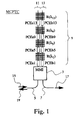
- a multichannel wavelength selective phase control unit MCPTC for use in a wavelength selective switch in accordance with the present invention comprises an MMI waveguide 3 of size 2x2, two access waveguides 5, 7 and an MI waveguide structure 9.
- Access waveguides 5, 7 are connected to the MMI waveguide 3 via two ports located at a first side of the MMI waveguide and the MI waveguide structure 9, which comprises two MI arms 11, 13, is connected to the MMI waveguide 3 via two ports located at an opposite side of the MMI waveguide.
- the two arms of the MI waveguide structure 9 comprise each a plurality of narrow band Bragg gratings of the reflection type denoted R and a plurality of phase control elements denoted PCE.
- the arm 11 comprises in order, as seen from the MMI waveguide, a phase control element PCEa1, a Bragg grating R( ⁇ 1 ), a phase control element PCEa5, a Bragg grating R( ⁇ 5 ), a phase control element PCEa9, a Bragg grating R( ⁇ 9 ), a phase control element PCEa13 and a Bragg grating R( ⁇ 13 ).
- the arm 13 comprises a phase control element PCEb1, a Bragg grating R( ⁇ 1 ), a phase control element PCEb5, a Bragg grating R( ⁇ 5 ), a phase control element PCEb9, a Bragg grating R( ⁇ 9 ), a phase control element PCEb13 and a Bragg grating R( ⁇ 13 ).
- the Bragg grating R( ⁇ 1 ) will reflect the channel ⁇ 1
- the Bragg gratings R( ⁇ 5 ) will reflect the channel ⁇ 5
- the Bragg gratings R( ⁇ 9 ) will reflect the channel ⁇ 9
- the Bragg gratings R( ⁇ 13 ) will reflect the channel ⁇ 13 .
- phase control elements PCEa1 and PCEb1 will control the phase of all channels in multiplex 15, while the phase control elements PCEa5 and PCEb5 will control the phase of the channels ⁇ 5 , ⁇ 9 , ⁇ 13 , the phase control elements PCEa9 and PCEb9 will control the phase of the channels ⁇ 9 and ⁇ 13 and finally the phase control elements PCEa12 and PCEb12 will only control the phase of the channel ⁇ 13 .
- the MI arms 11, 13 may be made arbitrarily long and be provided with an arbitrary number of Bragg gratings and phase control elements, such that the phase control unit MCPTC may control individually the phase of an arbitrary number of channels.
- MMIMI-based phase control units reference is made to earlier Swedish patent applications No. 9700865-0 , entitled Optical device and filed on 7 March 1997, and No. 9902512-4 , entitled Wavelength selective device and switch and method thereby and filed on 1 July 1999, filed by Applicant.
- the switch comprises two MMI waveguides 21, 23 interconnected by a Mach-Zehnder waveguide 25.
- the MMI waveguide 21 has an input port, to which an access waveguide 27 is connected for input of a wavelength multiplexed optical signal comprising 16 channels, ⁇ 1 , ⁇ 2 ,..., ⁇ 16 .
- the MMI waveguide 23 has two output ports, to which a respective access waveguide 29, 31 is connected for output of two separated signals.
- the Mach-Zehnder waveguide structure 25 comprises an upper arm 33 and a lower arm 35, which are arranged to transmit a respective portion of the intensity of the wavelength multiplexed optical signal.
- the upper arm comprises a demultiplexing unit 37 and a multiplexing unit 39 interconnected by four waveguides 41, 43, 47, 49 arranged in parallel.
- the demultiplexing unit 37 and the multiplexing unit 39 are preferably MMIMZI-based devices, see e.g. the publication A new type of tunable demultiplexer using a multi-leg Mach-Zehnder interferometer, J.-P. Weber et al, Proc. ECIO '97 EthE5, Sweden, pages 272-275, 1997 .
- Each waveguide 41, 43, 47, 49 is provided with a respective 49, 51, 53, 55 of the multichannel wavelength selective phase control unit MCPTC shown in Fig. 1, where, however, the Bragg gratings are tuned to different channels.
- the phase control unit 49 is thus arranged for phase tuning of the channels ⁇ 1 , ⁇ 5 , ⁇ 9 , ⁇ 13 , the phase control unit 51 is arranged for phase tuning of the channels ⁇ 2 , ⁇ 6 , ⁇ 10 , ⁇ 14 , the phase control unit 53 is arranged for phase tuning of the channels ⁇ 3 , ⁇ 7 , ⁇ 11 , ⁇ 15 and the phase control unit 55 is arranged for phase tuning of the channels ⁇ 4 , ⁇ 6 , ⁇ 12 , ⁇ 16 .
- the lower arm comprises a demultiplexing unit 57 and a multiplexing unit 59 connected by four waveguides 61, 63, 65, 67 arranged in parallel.
- the demultiplexing unit 57 and the multiplexing unit 59 are also preferably MMIMZI-based devices.
- Each waveguide 61, 63, 65, 67 is provided with a respective 69, 71, 73, 75 of the multichannel wavelength selective phase control unit MCPTC of Fig. 1, where, however, the Bragg gratings are tuned to different channels.
- the phase control unit 69 is thus arranged for phase tuning of the channels ⁇ 1 , ⁇ 5 , ⁇ 9 , ⁇ 13 , the phase control unit 71 is arranged for phase tuning of the channels ⁇ 2 , ⁇ 6 , ⁇ 10 , ⁇ 14 , the phase control unit 73 is arranged for phase tuning of the channels ⁇ 3 , ⁇ 7 , ⁇ 11 , ⁇ 15 and the phase control unit 75 is arranged for phase tuning of the channels ⁇ 4 , ⁇ 8 , ⁇ 12 , ⁇ 16 .
- phase control units 49, 51, 53, 55 and 69, 71, 73, 75, respectively may be arranged for phase tuning of other than the above-mentioned channels.
- the phase control units 49, 69 may e.g.
- phase control units 51, 71 may be arranged for phase tuning of the channels ⁇ 2 , ⁇ 6 , ⁇ 10 , ⁇ 14
- the phase control units 53, 73 may be arranged for phase tuning of the channels ⁇ 4 , ⁇ 8 , ⁇ 12 , ⁇ 16
- the phase control units 55, 75 may be arranged for phase tuning of the channels ⁇ 3 , ⁇ 7 , ⁇ 11 , ⁇ 15 .
- each of the channels may be output in waveguides 29 or 31 or be switched back into waveguide 27.
- Each channel is controlled by means of four phase control elements, e.g. the channel ⁇ 1 is e.g. controlled by means of the phase control elements PCEa1 and PCEb1 in unit 49 and by means of the phase control elements PCEa1 and PCEb1 in unit 69.
- the channel ⁇ 16 is controlled by means of the phase control elements PCEa16 and PCEb16 in unit 55 and by means of the phase control elements PCEa16 and PCEb16 in unit 75.
- the switch handles 16 channels and is similar to the switch shown in Fig. 2.
- the switch comprises two 4x4 MMI waveguides 81, 83 interconnected by a Mach-Zehnder waveguide structure 85 including four MZI arms 87, 89, 91, 93.
- the MMI waveguide 81 has four input ports 95, 97, 99 101 for inputting of the 16 channels, ⁇ 1 , ⁇ 2 , ... , ⁇ 16 .
- the MMI waveguide 83 has four output ports 103, 105, 107, 109 for outputting of four separated signals.
- Each arm 87, 89, 91, 93 comprises a structure such as the one included in arm 33 or arm 35 in Fig. 2, i.e. a demultiplexing unit, demux, and a multiplexing unit, mux, interconnected by means of four waveguides arranged in parallel.
- the demultiplexing unit and the multiplexing unit are preferably MMIMZI-based devices, see e.g. the above-mentioned publication by J.-P. Weber et al.
- each waveguide is provided with a respective of the multichannel wavelength selective phase control unit MCPTC of Fig. 1, where, however, the Bragg gratings are tuned to different channels.
- the uppermost phase control unit in each arm is thus arranged for phase tuning of the channels ⁇ 1 , ⁇ 5 , ⁇ 9 , ⁇ 13
- the second uppermost phase control unit in each arm is arranged for phase tuning of the channels ⁇ 2 , ⁇ 6 , ⁇ 10 , ⁇ 14
- the second lowest phase control unit in each arm is arranged for phase tuning of the channels ⁇ 3 , ⁇ 7 , ⁇ 11 , ⁇ 15
- the lowest phase control unit in each arm 87, 89, 91, 93 is arranged for phase tuning of the channels ⁇ 4 , ⁇ 8 , ⁇ 12 , ⁇ 16 .
- each of the channels may be output at any output port 103, 105, 107, 109 (or input port 95, 97, 99, 101).
- Each channel is in this case controlled by means of eight phase control elements.
- the switch is entirely scalable both as regards the number of input paths and output paths as well as the number of manageable channels. Further, a channel or channel multiplex may be input at an arbitrary one of the inputs and outputs of the apparatus.
- a multichannel wavelength selective phase control unit MCPTC2 for use in a wavelength selective switch in accordance with the present invention comprises an MMI waveguide 111 of size 2x2, two access waveguides 113, 115 and an MI waveguide structure 116.
- the access waveguides 113, 115 are connected to the MMI waveguide 111 via two ports located on a first side of the MMI waveguide and the MI waveguide structure 116, which comprises two MI arms 117, 119, is connected to the MMI waveguide 111 via two ports located on an opposite side of the MMI waveguide.
- the MI arms 117, 119 are each arranged to transmit a portion of the intensity of an optical wavelength multiplex.
- the two arms of the MI waveguide structure 116 comprise each a demultiplexing/multiplexing unit 121, at which four waveguides 123, 125, 127, 129 are arranged in parallel.
- the (de)multiplexing unit 121 is preferably an MMIMZI-based device, see e.g. the publication A new type of tunable demultiplexer using a multi-leg Mach-Zehnderinterferometer, J.-P. Weber et al, Proc.
- Each waveguide 123, 125, 127, 129 is provided with a plurality of phase control elements denoted PCE and a plurality of narrow band Bragg gratings of the reflection type denoted R.
- PCE phase control elements
- R narrow band Bragg gratings of the reflection type
- the waveguide 123 comprises in order, as seen from the MMI waveguide, a phase control element PCE1, a Bragg grating R( ⁇ 1 ), a phase control element PCE5, a Bragg grating R( ⁇ 5 ), etc. up to a phase control element PCE(Q-1)4+1, and a Bragg grating R( ⁇ (Q-1)4+1 ).
- the waveguide 125 comprises, as seen from the MMI waveguide, a phase control element PCE2, a Bragg grating R( ⁇ 2 ), a phase control element PCE6, a Bragg grating R( ⁇ 6 ), etc.
- the waveguide 127 comprises, as seen from the MMI waveguide, a phase control element PCE4, a Bragg grating R( ⁇ 4 ), a phase control element PCE8, a Bragg grating R( ⁇ 8 ), etc. up to a phase control element PCE(4Q), and a Bragg grating R( ⁇ (Q)4 ).
- the waveguide 129 comprises, as seen from the MMI waveguide, a phase control element PCE3, a Bragg grating R( ⁇ 3 ), a phase control element PCE7, a Bragg grating R( ⁇ 7 ), etc. up to a phase control element PCE(Q-1)4+3, and a Bragg grating R( ⁇ (Q-1)4+3) .
- the Bragg gratings R( ⁇ 1 ) will reflect the channel ⁇ 1
- the Bragg gratings R( ⁇ 2 ) will reflect the channel ⁇ 2
- the Bragg gratings R( ⁇ 3 ) will reflect the channel ⁇ 3 , etc.
- phase control elements PCE1 in the waveguides 117, 119 will control the phase of the channel ⁇ 1 in the multiplex 130
- phase control elements PCE2 in the waveguides 117, 119 will control the phase of the channel ⁇ 2 in the multiplex 130
- phase control elements PCE3 in the waveguides 117, 119 will control the phase of the channel ⁇ 3 in the multiplex 130, etc.
- the switch comprises two MMI waveguides 133, 134 interconnected by means of a Mach-Zehnder waveguide structure 136.
- the MMI waveguide 133 has four input ports 135, 137, 139, 141 for inputting of up to 4Q wavelengths channels ⁇ 1 , ⁇ 2 ,..., ⁇ 4Q .
- the MMI waveguide 134 has four output ports 143, 145, 147, 149 for outputting of separated signals.
- the Mach-Zehnder waveguide structure 136 comprises four arms 151, 153, 155, 157, which are each arranged to transmit a respective portion of the intensity of channels input into the switch.
- Each of the four arms 151, 153, 155, 157 is provided with a respective multichannel wavelength selective phase control unit MCPTC2, as shown in Fig. 4, where each unit comprises 4Q Bragg gratings for handling of 4Q channels or channel groups.
- each of the channels can be output at any output port 143, 145, 147, 149 (or input port 135, 137, 139, 141).
- Each channel is controlled individually by means of eight phase control elements in the switch.
- the switch is entirely scalable both as regards the number of inputs and outputs as well as regards the number of manageable channels.
- a 32 channel wavelength selective phase control unit MCPTC3 for use in a wavelength selective switch in accordance with the present invention comprises an MMI waveguide 161 of size 2x2, two access waveguides 163, 165 and an MI waveguide structure 166.
- Access waveguides 163, 165 are connected to the MMI waveguide 161 via two ports located on a first side of the MMI waveguide and the MI waveguide structure 166, which comprises two MI arms 167, 169, is connected to the MMI waveguide 161 via two ports located on an opposite side of the MMI waveguide.
- the MI arms 167, 169 are identical to the MI arms 117, 119 in Fig.
- each of them between the respective (de)multiplexing unit and MMI waveguide 161, comprises a Bragg grating R( ⁇ 17 , ⁇ 18 , ..., ⁇ 32 ) arranged to reflect 16 channels ⁇ 17 , ⁇ 18 , ..., ⁇ 32 and a controllable phase control element 168.
- an optical channel multiplex 170 comprising channels ⁇ 1 , ⁇ 2 , ..., ⁇ 32 is input into the unit via the access waveguide 163, the Bragg gratings R( ⁇ 1 ) will reflect the channel ⁇ 1 , the Bragg gratings R( ⁇ 2 ) will reflect the channel ⁇ 2 , the Bragg gratings R( ⁇ 3 ) will reflect the channel ⁇ 3 , etc. for the channels ⁇ 1 - ⁇ 16 .
- the channels ⁇ 17 - ⁇ 32 will all be reflected by the Bragg gratings R( ⁇ 17 , ⁇ 18 , ..., ⁇ 32 ).
- phase control elements PCE1 in the waveguides 167, 169 will control the phase of the channel ⁇ 1 in the multiplex 170
- the phase control elements PCE2 in the waveguides 167, 169 will control the phase of the channel ⁇ 2 in the multiplex 170
- the phase control elements PCE3 in the waveguides 167, 169 will control the phase of the channel ⁇ 3 in the multiplex 170, etc. for the channels ⁇ 1 - ⁇ 16
- the channels ⁇ 17 - ⁇ 32 will all be phase-controlled by means of phase control elements 168. Through this arrangement it is thus possible to control channel-individually the phase of the channels ⁇ 1 - ⁇ 16 in the multiplex 170.
- the channels ⁇ 17 - ⁇ 32 cannot be phase-controlled individually.
- it is possible to control the phases in respective arms 167, 169 such that the channels are output in the access waveguides 165 as output 171 or back into the access waveguide 163 as output 172.
- the switch comprises two MMI waveguides 173, 174 interconnected by means of a Mach-Zehnder waveguide structure 176.
- the MMI waveguide 173 has two input ports 175, 177 for inputting of up to 32 wavelength channels ⁇ 1 , ⁇ 2 , ..., ⁇ 32 .
- the MMI waveguide 174 has two output ports 179, 181 for outputting of separated signals.
- the Mach-Zehnder waveguide structure 176 comprises two arms 182, 183, which each is arranged to transmit a respective portion of the intensity of input channels in the switch.
- Each of the arms 182, 183 is provided with two respective multichannel wavelength selective phase control units MCPTC3 of the type shown in Fig. 6 arranged in series.
- the first multichannel wavelength selective phase control unit MCPTC3 in each arm is arranged for individual phase control of the channels ⁇ 1 - ⁇ 16
- the second multichannel wavelength selective phase control unit MCPTC3 in each arm is arranged for individual phase control of the channels ⁇ 17 - ⁇ 32
- PC( ⁇ 1 , ⁇ 2 , ..., ⁇ 16 ) is identical with the unit shown in Fig.
- PC( ⁇ 17 , ⁇ 18 , ..., ⁇ 32 ) is arranged such that the channels ⁇ 1 - ⁇ 16 are reflected by a Bragg grating and the channels ⁇ 17 - ⁇ 32 are reflected in respective arms 167, 169.
- each of the channels ⁇ 1 - ⁇ 32 is controlled individually by means of four phase control elements in the switch. If the two units PC( ⁇ 17 , ⁇ 18 , ..., ⁇ 32 ) are omitted, completely individual switching possibilities for the input channels ⁇ 1 - ⁇ 16 are obtained, while the channels ⁇ 17 - ⁇ 32 are switched together as a multiplex through the switch under control of only two phase control elements per MZI arm.
- a multichannel wavelength selective phase control unit MCPTC4 for use in a wavelength selective switch in accordance with the present invention comprises an MMI waveguide 191 of size 2x2, two access waveguides 193, 195 and an MI waveguide structure 196.
- Access waveguides 193, 195 are connected to the MMI waveguide 191 via two ports located on a first side of the MMI waveguide and the MI waveguide structure 196, which comprises two MI arms 197, 199, is connected to the MMI waveguide 191 via two ports located on an opposite side of the MMI waveguide.
- the MI arms 197, 199 are identical to the MI arms 117, 119 in Fig.
- MN+1, MN+2, ..., MN+4Q (M, N and Q are positive integers) except that each of them, between the respective (de)multiplexing unit and MMI waveguide 161, comprises M Bragg gratings R( ⁇ 1 , ⁇ 2 , ..., ⁇ N ); R( ⁇ N+1 , ⁇ N+2 , ..., ⁇ 2N ); ...; R( ⁇ (M-1)N+1 , ⁇ (M-1)N+2 , ..., ⁇ MN ) arranged to reflect respective channel groups ⁇ 1 , ⁇ 2 , ..., ⁇ N ; ⁇ N+1 , ⁇ N+2 , ..., ⁇ 2N ; ... ; ⁇ (M-1)N+1 , ⁇ (M-1)N+2 , ..., ⁇ MN and M controllable phase control elements PCEN, PCE2N, ..., PCEMN.
- an optical channel multiplex 200 comprising the channels ⁇ 1 , ⁇ 2 , ..., ⁇ MN , ⁇ MN+1 , ⁇ MN+2 , ..., ⁇ MN+4Q is input to the unit via the access waveguide 193, the Bragg gratings R( ⁇ 1 , ⁇ 2 , ..., ⁇ N ); R( ⁇ N+1 , ⁇ N+2 , ..., ⁇ 2N ); ...; R( ⁇ (M-1)N+1 , ⁇ (M-1)N+2 , ..., ⁇ MN ) Will reflect the respective channel groups ⁇ 1 , ⁇ 2 , ..., ⁇ N ; ⁇ N+1 , ⁇ N+2 , ..., ⁇ 2N ; ..., ⁇ (M-1)N+1 , ⁇ (M-1)N+2 , ..., ⁇ MN and the Bragg gratings R( ⁇ MN+1 ) will reflect the channel ⁇ MN+1 , the
- phase control element PCEN in the waveguides 197, 199 will thus control the phase of the channels ⁇ 1 - ⁇ N in the multiplex 200
- the phase control element PCE2N in the waveguides 197, 199 will control the phase of the channels ⁇ N+1 - ⁇ 2N etc. for the M channel groups.
- phase control elements PCEMN+1 in the waveguides 197, 199 will control the phase of the channel ⁇ MN+1 in the multiplex 200
- the phase control elements PCEMN+2 in the waveguides 197, 199 will control the phase of the channel ⁇ MN+2 in the multiplex 200
- the phase control elements PCEMN+3 in the waveguides 197, 199 will control the phase of the channel ⁇ MN+3 in the multiplex, 200 etc. for the channels ⁇ MN+1 - ⁇ MN+4Q .
- the switch comprises two MMI waveguides 203, 204 connected by means of a Mach-Zehnder waveguide structure 206.
- the MMI waveguide 203 has two input ports 205, 207 for inputting of up to MN+4Q wavelength channels ⁇ 1 , ⁇ 2 ,... X MN+4Q .
- the MMI waveguide 204 has two output ports 209, 211 for outputting of separated signals.
- the Mach-Zehnder waveguide structure 206 comprises two arms 212, 213, which each is arranged to transmit a respective portion of the intensity of the channels input in the switch.
- Each of the arms 212, 213 is provided with M+1 respective multichannel wavelength selective phase control units MCPTC4 of the type shown in Fig. 8 arranged in series.
- the first multichannel wavelength selective phase control unit MCPTC4 in each arm is arranged for individual phase control of the channels ⁇ 1 - ⁇ N
- the second multichannel wavelength selective phase control unit MCPTC4 in each arm is arranged for individual phase control of the channels ⁇ N+1 - ⁇ 2N
- PC( ⁇ (M-1)N+1 , ⁇ (M-1)N+2 , ..., ⁇ MN which is arranged for individual phase control of the channels ⁇ (M-1)N+1 - ⁇ MN .
- PC( ⁇ MN+1 , ⁇ MN+2 , ..., ⁇ MN+4Q ) is arranged for individual phase control of the channels ⁇ MN+1 - ⁇ MN+4Q .
- Each phase control unit is modified, such that the channels, which it phase controls individually, are arranged to be reflected in the arms 197, 199.
- the unit PC( ⁇ MN+1 , ⁇ MN+2 , ..., ⁇ MN+4Q ) is identical to the unit shown in Fig. 8, while the rest of the units are phase-tuned to other channels.
- each of the channels may be output at any output port 209, 211.
- Each of the channels ⁇ 1 - ⁇ MN+4Q is controlled individually by means of four phase control elements in the switch.
- the switch according to the fourth and fifth embodiments of the invention is entirely scalable both as regards the number of inputs and outputs as well as the number of manageable channels.
Landscapes
- Physics & Mathematics (AREA)
- Engineering & Computer Science (AREA)
- Computer Networks & Wireless Communication (AREA)
- Nonlinear Science (AREA)
- Signal Processing (AREA)
- General Physics & Mathematics (AREA)
- Optics & Photonics (AREA)
- Optical Integrated Circuits (AREA)
- Optical Modulation, Optical Deflection, Nonlinear Optics, Optical Demodulation, Optical Logic Elements (AREA)
- Lasers (AREA)
- Optical Communication System (AREA)
Claims (19)
- Appareil pour la commutation sélective en longueur d'onde d'une pluralité de canaux de longueur d'onde optiques, comprenant deux guides d'ondes à Interférence Multi Mode, appelés ci-après MMI (Multi Mode Interference) (21, 23 ; 81, 83 ; 133, 134 ; 173, 174 ; 203, 204) interconnectés par au moins deux structures de guides d'ondes de Mach-Zehnder (25 ; 85 ; 136 ; 176 ; 206) disposées en parallèle, dont chacune est conçue pour transmettre une partie respective de l'intensité de ladite pluralité de canaux de longueurs d'onde optiques, caractérisé en ce que chaque structure de guide d'ondes de Mach-Zehnder comprend :- une unité de démultiplexage (35, 57 ; 121), une unité de multiplexage (39, 59 ; 121) et au moins deux guides d'ondes (41, 43, 45, 47, 61, 63, 65, 67 ; 123, 125, 127, 129) disposés en parallèle, dans lequel :- l'unité de démultiplexage est conçue pour le démultiplexage de ladite pluralité de canaux de longueurs d'onde optiques en au moins deux groupes de canaux ;- chaque guide d'ondes est disposé en parallèle pour la transmission de l'un respectif desdits groupes de canaux à l'unité de multiplexage et est en outre muni d'une unité de commande de phase sélective en longueur d'onde multicanaux respective (MCPTC ; MCPTC2 ; MCPTC3 ; MCPTC4) conçue pour la commande de phase individuelle d'au moins certains canaux dans lesdits groupes de canaux respectifs transmis à l'unité de multiplexage ; et- l'unité de multiplexage est conçue pour le multiplexage desdits groupes de canaux.
- Appareil selon la revendication 1, dans lequel l'unité de démultiplexage est un dispositif (37, 57) d'Interféromètre de Mach-Zehnder à Interférence Multi Mode, appelé ci-après Interféromètre MMIMZI (pour Multi Mode Interference Mach-Zehnder Interferometer), dans lequel chaque bras de l'Interféromètre de Mach-Zehnder, appelé ci-après MZI (Mach-Zehnder Interferometer) comprend un élément de commande de phase ou d'ajustement de phase.
- Appareil selon la revendication 1 ou 2, dans lequel l'unité de multiplexage est un dispositif à base d'interféromètre MMIMZI (39, 59), dans lequel chaque bras MZI comprend un élément de commande de phase ou d'ajustement de phase.
- Appareil selon l'une quelconque des revendications 1 à 3, dans lequel l'unité de démultiplexage et l'unité de multiplexage sont interconnectées par les au moins deux guides d'ondes disposés en parallèle.
- Appareil selon l'une quelconque des revendications 1 à 4, dans lequel chaque unité de commande sélective en longueur d'onde multicanaux (MCPTC) est un dispositif à base de Michelson à Interférence Multi Mode, appelé ci-après Interféromètre MMIMI, dans lequel chaque bras de dispositif de Michelson, appelé ci-après MI (11, 13) comprend au moins, lorsqu'on l'observe depuis le guide d'ondes MMI (3), un premier élément de commande de phase (PCEa1, PCEb1), un premier réseau de diffraction de Bragg (R(λ1)), un deuxième élément de commande de phase (PCEa5, PCEb5) et un deuxième réseau de diffraction de Bragg (R(λ5)), le premier réseau de diffraction de Bragg étant conçu pour la réflexion d'au moins un premier canal dans celui desdits groupes de canaux qui est traité par l'unité de commande de phase, le deuxième réseau de diffraction de Bragg étant conçu pour la réflexion d'au moins un deuxième canal dans celui desdits groupes de canaux qui est traité par l'unité de commande de phase, et les éléments de commande de phase étant conçus pour la commande de phase des canaux correspondants, qui sont transmis à travers eux.
- Appareil selon la revendication 1, dans lequel chaque structure de guide d'ondes de Mach-Zehnder (136 ; 176; 206) comprend une configuration à base de MMIMI (116 ; 166 ; 196), dans lequel chaque bras MI (117, 119 ; 167, 169 ; 197, 199) comprend l'une respective de ladite unité de démultiplexage et de ladite unité de multiplexage (121).
- Appareil selon la revendication 6, dans lequel ladite unité de démultiplexage et ladite unité de multiplexage (121) du bras MI respectif sont constituées d'une unité de démultiplexage/multiplexage à base de MZI (121).
- Appareil selon la revendication 7, dans lequel chaque unité de démultiplexage/multiplexage est munie d'au moins deux guides d'ondes (123, 125, 127, 129) disposés en parallèle, dans lequel chaque guide d'ondes est muni de réseaux de diffraction de Bragg et d'éléments de commande de phase conçus pour la commande de phase individuelle d'au moins certains canaux dans celui desdits groupes de canaux qui est transmis dans le guide d'ondes.
- Appareil selon la revendication 8, dans lequel chaque unité de commande de phase sélective en longueur d'onde multicanaux comprend au moins, lorsqu'on l'observe depuis l'unité de démultiplexage/multiplexage, un premier élément de commande de phase (PCE1, PCE2, PCE4, PCE3), un premier réseau de diffraction de Bragg (R(λ1), R(λ2), R(λ4), R(λ3)), un deuxième élément de commande de phase (PCE5, PCE6, PCE8, PCE7) et un deuxième réseau de diffraction de Bragg (R(λ5), R (λ6), R(λ8), R(λ7)), le premier réseau de diffraction de Bragg étant conçu pour la réflexion d'au moins un premier canal dans celui desdits groupes de canaux qui est traité par l'unité de commande de phase, le deuxième réseau de diffraction de Bragg étant conçu pour la réflexion d'au moins un deuxième canal dans celui desdits groupes de canaux qui est traité par l'unité de commande de phase, et les éléments de commande de phase étant conçus pour la commande de phase de canaux respectifs qui sont transmis à travers eux.
- Appareil selon l'une quelconque des revendications 6 à 9, dans lequel chaque bras MI (167, 169 ; 197, 199) de la configuration à base de MMIMI comprend un réseau de diffraction de Bragg (R(λ17, λ18, ..., λ32) ; R(λ1, λ2, ..., λN) ) , situé entre les guides d'ondes MMI (161 ; 191) de la configuration à base de MMIMI et ladite unité de démultiplexage/multiplexage à base de MZI (121), ledit réseau de diffraction de Bragg étant conçu pour la réflexion d'au moins certains de ladite pluralité de canaux de longueurs d'onde optiques.
- Appareil selon la revendication 10, dans lequel au moins un certain bras MI de la configuration à base de MMIMI comprend un élément de commande de phase (168 ; PCEN) situé entre les guides d'ondes MMI (161 ; 191) de la configuration à base de MMIMI et ledit réseau de diffraction de Bragg (R(λ17, λ18, ..., λ32) ; (R(λ1, λ2, ..., λN)), qui est conçu pour la réflexion desdits au moins certains de ladite pluralité de canaux de longueurs d'onde optiques.
- Appareil selon l'une quelconque des revendications 1 à 11, dans lequel lesdits deux guides d'ondes MMI interconnectés par lesdites structures de guides d'ondes de Mach-Zehnder disposées en parallèle ont une taille de 2x2 et le nombre de structures de guides d'ondes de Mach-Zehnder disposées en parallèle est égal à deux.
- Appareil selon l'une quelconque des revendications 1 à 12, dans lequel lesdits deux guides d'ondes MMI interconnectés par lesdites structures de guides d'ondes de Mach-Zehnder disposées en parallèle ont au moins une taille de 4x4 et le nombre de structures de guides d'ondes de Mach-Zehnder disposées en parallèle est au moins égal à quatre.
- Appareil selon l'une quelconque des revendications 1 à 13, dans lequel ladite pluralité de canaux de longueurs d'onde optiques comprend au moins quatre canaux.
- Appareil selon l'une quelconque des revendications 1 à 14, dans lequel ladite pluralité de canaux de longueurs d'onde optiques comprend au moins huit canaux.
- Appareil selon l'une quelconque des revendications 1 à 15, dans lequel ladite pluralité de canaux de longueurs d'onde optiques comprend au moins 16 canaux.
- Appareil selon l'une quelconque des revendications 1 à 16, conçu pour la commutation individuelle de chaque canal dans chaque groupe de canaux.
- Appareil selon l'une quelconque des revendications 1 à 16, conçu pour la commutation conjointe de tous les canaux dans au moins un certain groupe de canaux.
- Procédé pour la commutation sélective en longueur d'onde d'une pluralité de canaux de longueurs d'onde optiques dans un appareil comprenant deux guides d'ondes MMI (21, 23 ; 81, 83 ; 133, 134 ; 173, 174 ; 203, 204) interconnectés par au moins deux structures de guides d'ondes de Mach-Zehnder (25 ; 85 ; 136 ; 176 ; 206) disposées en parallèle, chacune d'entre elles étant conçue pour transmettre une partie respective de l'intensité de ladite pluralité de canaux de longueurs d'onde optiques, caractérisé par l'exécution des étapes suivantes dans chaque structure de guide d'ondes de Mach-Zehnder :- le démultiplexage de ladite pluralité de canaux de longueurs d'onde optiques en au moins deux groupes de canaux au moyen d'une unité de démultiplexage (37, 57 ; 121) ;- la transmission d'un groupe de canaux respectif à une unité de multiplexage (39, 59 ; 121) au moyen d'un guide d'ondes respectif (41, 43, 45, 47, 61, 63, 65, 67 ; 123, 125, 127, 129) disposé en parallèle ;- la commande de phase individuelle d'au moins certains canaux dans un groupe de canaux respectif qui est transmis à l'unité de multiplexage, au moyen d'une unité de commande de phase sélective en longueur d'onde respective (MCPTC ; MCPTC2 ; MCPTC3 ; MCPTC4) disposée sur un guide d'ondes respectif disposé en parallèle ; et- le multiplexage desdits groupes de canaux au moyen de l'unité de multiplexage.
Applications Claiming Priority (3)
| Application Number | Priority Date | Filing Date | Title |
|---|---|---|---|
| SE0001619A SE522903C2 (sv) | 2000-05-03 | 2000-05-03 | Anordning och förfarande för våglängdsselektiv omkoppling |
| SE0001619 | 2000-05-03 | ||
| PCT/SE2001/000918 WO2001084759A1 (fr) | 2000-05-03 | 2001-04-27 | Appareil et procede de commutation spectrale selective |
Publications (2)
| Publication Number | Publication Date |
|---|---|
| EP1266473A1 EP1266473A1 (fr) | 2002-12-18 |
| EP1266473B1 true EP1266473B1 (fr) | 2007-08-15 |
Family
ID=20279525
Family Applications (1)
| Application Number | Title | Priority Date | Filing Date |
|---|---|---|---|
| EP01926304A Expired - Lifetime EP1266473B1 (fr) | 2000-05-03 | 2001-04-27 | Appareil et procede de commutation spectrale selective |
Country Status (8)
| Country | Link |
|---|---|
| US (1) | US6574391B2 (fr) |
| EP (1) | EP1266473B1 (fr) |
| AT (1) | ATE370565T1 (fr) |
| AU (1) | AU2001252834A1 (fr) |
| DE (1) | DE60129936T2 (fr) |
| SE (1) | SE522903C2 (fr) |
| TW (1) | TW476201B (fr) |
| WO (1) | WO2001084759A1 (fr) |
Families Citing this family (9)
| Publication number | Priority date | Publication date | Assignee | Title |
|---|---|---|---|---|
| US20030058505A1 (en) * | 2001-09-26 | 2003-03-27 | Joseph Arol | Passive distribution of wavelengths in optical networks |
| US7321705B2 (en) * | 2002-05-28 | 2008-01-22 | Optun (Bvi) Ltd. | Method and device for optical switching and variable optical attenuation |
| US6888846B2 (en) * | 2002-07-11 | 2005-05-03 | Flexlight Networks | Data transfer in an optical network communication system |
| GB2404034A (en) * | 2003-07-17 | 2005-01-19 | Dow Corning Ltd | An electro-optically tunable optical filter |
| US20060002653A1 (en) * | 2004-06-30 | 2006-01-05 | Anders Grunnet-Jepsen | Apparatus for an optical circuit having a flat wavelength response |
| US10481333B2 (en) * | 2017-07-06 | 2019-11-19 | Macom Technology Solutions Holdings, Inc. | Athermal silicon photonics wavelength locker and meter |
| CN110208904B (zh) * | 2018-02-28 | 2022-02-18 | 华为技术有限公司 | 光波导装置 |
| CN115276804A (zh) * | 2021-04-30 | 2022-11-01 | 华为技术有限公司 | 一种光功率调节系统和光功率调节装置 |
| US20250110272A1 (en) * | 2023-09-28 | 2025-04-03 | Apple Inc. | Photonic switch with multi-wavelength routing capabilities |
Family Cites Families (7)
| Publication number | Priority date | Publication date | Assignee | Title |
|---|---|---|---|---|
| US5933554A (en) * | 1995-02-01 | 1999-08-03 | Leuthold; Juerg | Compact optical-optical switches and wavelength converters by means of multimode interference mode converters |
| US5915051A (en) * | 1997-01-21 | 1999-06-22 | Massascusetts Institute Of Technology | Wavelength-selective optical add/drop switch |
| EP0933963A3 (fr) * | 1998-01-30 | 2000-09-20 | Jds Fitel Inc. | Diviseur de puissance optique à rapport variable et commutateurs optiques |
| US6351581B1 (en) * | 1998-03-17 | 2002-02-26 | Agere Systems Optoelectronics Guardian Corp. | Optical add-drop multiplexer having an interferometer structure |
| US6212315B1 (en) * | 1998-07-07 | 2001-04-03 | Lucent Technologies Inc. | Channel power equalizer for a wavelength division multiplexed system |
| SE514576C2 (sv) * | 1998-09-22 | 2001-03-12 | Ericsson Telefon Ab L M | Anordning och förfarande för avstämbar Add/Drop- Multiplexering |
| US6337755B1 (en) * | 1998-11-17 | 2002-01-08 | Qtera Corporation | Polarization independent all-optical regenerators |
-
2000
- 2000-05-03 SE SE0001619A patent/SE522903C2/sv unknown
- 2000-05-30 TW TW089110518A patent/TW476201B/zh not_active IP Right Cessation
-
2001
- 2001-04-27 AU AU2001252834A patent/AU2001252834A1/en not_active Abandoned
- 2001-04-27 DE DE60129936T patent/DE60129936T2/de not_active Expired - Lifetime
- 2001-04-27 EP EP01926304A patent/EP1266473B1/fr not_active Expired - Lifetime
- 2001-04-27 AT AT01926304T patent/ATE370565T1/de not_active IP Right Cessation
- 2001-04-27 WO PCT/SE2001/000918 patent/WO2001084759A1/fr not_active Ceased
- 2001-05-02 US US09/846,305 patent/US6574391B2/en not_active Expired - Lifetime
Also Published As
| Publication number | Publication date |
|---|---|
| US6574391B2 (en) | 2003-06-03 |
| SE0001619D0 (sv) | 2000-05-03 |
| TW476201B (en) | 2002-02-11 |
| DE60129936T2 (de) | 2008-05-15 |
| WO2001084759A1 (fr) | 2001-11-08 |
| SE0001619L (sv) | 2001-11-04 |
| US20010038735A1 (en) | 2001-11-08 |
| EP1266473A1 (fr) | 2002-12-18 |
| DE60129936D1 (de) | 2007-09-27 |
| ATE370565T1 (de) | 2007-09-15 |
| SE522903C2 (sv) | 2004-03-16 |
| AU2001252834A1 (en) | 2001-11-12 |
Similar Documents
| Publication | Publication Date | Title |
|---|---|---|
| US5953467A (en) | Switchable optical filter | |
| US6005992A (en) | Optical device | |
| US6504970B2 (en) | Planar lightwave wavelength blocker | |
| US6956987B2 (en) | Planar lightwave wavelength blocker devices using micromachines | |
| EP1266473B1 (fr) | Appareil et procede de commutation spectrale selective | |
| US6571031B1 (en) | Device for multiplexing/demultiplexing and method therewith | |
| US6600852B1 (en) | Wavelength selective device and switch and method thereby | |
| EP1116346B1 (fr) | Multiplexeur a insertion-extraction reglable | |
| WO2001095538A1 (fr) | Coupleur mmimi assiste par reseau de bragg et destine au multiplexage a insertion/extraction accordable | |
| EP1266471B1 (fr) | Dispositif et procede de multiplexage a insertion/extraction optique | |
| US10484122B2 (en) | Optical add/drop multiplexer and control method thereof, and transceiver | |
| US6724952B2 (en) | Wavelength selective cross-connect (WSC) | |
| Dingel et al. | Photonic add-drop multiplexing perspective for next-generation optical networks | |
| Rostami et al. | An Optical Integrated system for Implementation of Optical Cross-connect, Beam Splitter, Mux/demux and Combiner |
Legal Events
| Date | Code | Title | Description |
|---|---|---|---|
| PUAI | Public reference made under article 153(3) epc to a published international application that has entered the european phase |
Free format text: ORIGINAL CODE: 0009012 |
|
| 17P | Request for examination filed |
Effective date: 20021015 |
|
| AK | Designated contracting states |
Kind code of ref document: A1 Designated state(s): AT BE CH CY DE DK ES FI FR GB GR IE IT LI LU MC NL PT SE TR |
|
| AX | Request for extension of the european patent |
Free format text: AL;LT;LV;MK;RO;SI |
|
| RAP1 | Party data changed (applicant data changed or rights of an application transferred) |
Owner name: TELEFONAKTIEBOLAGET LM ERICSSON (PUBL) |
|
| 17Q | First examination report despatched |
Effective date: 20060706 |
|
| GRAP | Despatch of communication of intention to grant a patent |
Free format text: ORIGINAL CODE: EPIDOSNIGR1 |
|
| GRAS | Grant fee paid |
Free format text: ORIGINAL CODE: EPIDOSNIGR3 |
|
| GRAA | (expected) grant |
Free format text: ORIGINAL CODE: 0009210 |
|
| AK | Designated contracting states |
Kind code of ref document: B1 Designated state(s): AT BE CH CY DE DK ES FI FR GB GR IE IT LI LU MC NL PT SE TR |
|
| REG | Reference to a national code |
Ref country code: GB Ref legal event code: FG4D |
|
| REG | Reference to a national code |
Ref country code: CH Ref legal event code: EP |
|
| REG | Reference to a national code |
Ref country code: IE Ref legal event code: FG4D |
|
| REF | Corresponds to: |
Ref document number: 60129936 Country of ref document: DE Date of ref document: 20070927 Kind code of ref document: P |
|
| PG25 | Lapsed in a contracting state [announced via postgrant information from national office to epo] |
Ref country code: ES Free format text: LAPSE BECAUSE OF FAILURE TO SUBMIT A TRANSLATION OF THE DESCRIPTION OR TO PAY THE FEE WITHIN THE PRESCRIBED TIME-LIMIT Effective date: 20071126 Ref country code: NL Free format text: LAPSE BECAUSE OF FAILURE TO SUBMIT A TRANSLATION OF THE DESCRIPTION OR TO PAY THE FEE WITHIN THE PRESCRIBED TIME-LIMIT Effective date: 20070815 Ref country code: FI Free format text: LAPSE BECAUSE OF FAILURE TO SUBMIT A TRANSLATION OF THE DESCRIPTION OR TO PAY THE FEE WITHIN THE PRESCRIBED TIME-LIMIT Effective date: 20070815 |
|
| NLV1 | Nl: lapsed or annulled due to failure to fulfill the requirements of art. 29p and 29m of the patents act | ||
| PG25 | Lapsed in a contracting state [announced via postgrant information from national office to epo] |
Ref country code: LI Free format text: LAPSE BECAUSE OF FAILURE TO SUBMIT A TRANSLATION OF THE DESCRIPTION OR TO PAY THE FEE WITHIN THE PRESCRIBED TIME-LIMIT Effective date: 20070815 Ref country code: AT Free format text: LAPSE BECAUSE OF FAILURE TO SUBMIT A TRANSLATION OF THE DESCRIPTION OR TO PAY THE FEE WITHIN THE PRESCRIBED TIME-LIMIT Effective date: 20070815 Ref country code: CH Free format text: LAPSE BECAUSE OF FAILURE TO SUBMIT A TRANSLATION OF THE DESCRIPTION OR TO PAY THE FEE WITHIN THE PRESCRIBED TIME-LIMIT Effective date: 20070815 |
|
| REG | Reference to a national code |
Ref country code: CH Ref legal event code: PL |
|
| ET | Fr: translation filed | ||
| PG25 | Lapsed in a contracting state [announced via postgrant information from national office to epo] |
Ref country code: BE Free format text: LAPSE BECAUSE OF FAILURE TO SUBMIT A TRANSLATION OF THE DESCRIPTION OR TO PAY THE FEE WITHIN THE PRESCRIBED TIME-LIMIT Effective date: 20070815 |
|
| PG25 | Lapsed in a contracting state [announced via postgrant information from national office to epo] |
Ref country code: GR Free format text: LAPSE BECAUSE OF FAILURE TO SUBMIT A TRANSLATION OF THE DESCRIPTION OR TO PAY THE FEE WITHIN THE PRESCRIBED TIME-LIMIT Effective date: 20071116 Ref country code: DK Free format text: LAPSE BECAUSE OF FAILURE TO SUBMIT A TRANSLATION OF THE DESCRIPTION OR TO PAY THE FEE WITHIN THE PRESCRIBED TIME-LIMIT Effective date: 20070815 |
|
| PG25 | Lapsed in a contracting state [announced via postgrant information from national office to epo] |
Ref country code: PT Free format text: LAPSE BECAUSE OF FAILURE TO SUBMIT A TRANSLATION OF THE DESCRIPTION OR TO PAY THE FEE WITHIN THE PRESCRIBED TIME-LIMIT Effective date: 20080115 |
|
| PLBE | No opposition filed within time limit |
Free format text: ORIGINAL CODE: 0009261 |
|
| STAA | Information on the status of an ep patent application or granted ep patent |
Free format text: STATUS: NO OPPOSITION FILED WITHIN TIME LIMIT |
|
| PG25 | Lapsed in a contracting state [announced via postgrant information from national office to epo] |
Ref country code: SE Free format text: LAPSE BECAUSE OF FAILURE TO SUBMIT A TRANSLATION OF THE DESCRIPTION OR TO PAY THE FEE WITHIN THE PRESCRIBED TIME-LIMIT Effective date: 20071115 |
|
| 26N | No opposition filed |
Effective date: 20080516 |
|
| PG25 | Lapsed in a contracting state [announced via postgrant information from national office to epo] |
Ref country code: MC Free format text: LAPSE BECAUSE OF NON-PAYMENT OF DUE FEES Effective date: 20080430 |
|
| PG25 | Lapsed in a contracting state [announced via postgrant information from national office to epo] |
Ref country code: IE Free format text: LAPSE BECAUSE OF NON-PAYMENT OF DUE FEES Effective date: 20080428 |
|
| PG25 | Lapsed in a contracting state [announced via postgrant information from national office to epo] |
Ref country code: CY Free format text: LAPSE BECAUSE OF FAILURE TO SUBMIT A TRANSLATION OF THE DESCRIPTION OR TO PAY THE FEE WITHIN THE PRESCRIBED TIME-LIMIT Effective date: 20070815 |
|
| PG25 | Lapsed in a contracting state [announced via postgrant information from national office to epo] |
Ref country code: LU Free format text: LAPSE BECAUSE OF NON-PAYMENT OF DUE FEES Effective date: 20080427 |
|
| PG25 | Lapsed in a contracting state [announced via postgrant information from national office to epo] |
Ref country code: TR Free format text: LAPSE BECAUSE OF FAILURE TO SUBMIT A TRANSLATION OF THE DESCRIPTION OR TO PAY THE FEE WITHIN THE PRESCRIBED TIME-LIMIT Effective date: 20070815 |
|
| PG25 | Lapsed in a contracting state [announced via postgrant information from national office to epo] |
Ref country code: IT Free format text: LAPSE BECAUSE OF NON-PAYMENT OF DUE FEES Effective date: 20080430 |
|
| REG | Reference to a national code |
Ref country code: FR Ref legal event code: PLFP Year of fee payment: 15 |
|
| PGFP | Annual fee paid to national office [announced via postgrant information from national office to epo] |
Ref country code: GB Payment date: 20150427 Year of fee payment: 15 Ref country code: DE Payment date: 20150429 Year of fee payment: 15 |
|
| PGFP | Annual fee paid to national office [announced via postgrant information from national office to epo] |
Ref country code: FR Payment date: 20150417 Year of fee payment: 15 |
|
| REG | Reference to a national code |
Ref country code: DE Ref legal event code: R119 Ref document number: 60129936 Country of ref document: DE |
|
| GBPC | Gb: european patent ceased through non-payment of renewal fee |
Effective date: 20160427 |
|
| REG | Reference to a national code |
Ref country code: FR Ref legal event code: ST Effective date: 20161230 |
|
| PG25 | Lapsed in a contracting state [announced via postgrant information from national office to epo] |
Ref country code: FR Free format text: LAPSE BECAUSE OF NON-PAYMENT OF DUE FEES Effective date: 20160502 Ref country code: DE Free format text: LAPSE BECAUSE OF NON-PAYMENT OF DUE FEES Effective date: 20161101 Ref country code: GB Free format text: LAPSE BECAUSE OF NON-PAYMENT OF DUE FEES Effective date: 20160427 |