EP1266612A2 - Vorrichtung zur Gewebeerkennung mittels mehrerer Messtechniken - Google Patents
Vorrichtung zur Gewebeerkennung mittels mehrerer Messtechniken Download PDFInfo
- Publication number
- EP1266612A2 EP1266612A2 EP02254165A EP02254165A EP1266612A2 EP 1266612 A2 EP1266612 A2 EP 1266612A2 EP 02254165 A EP02254165 A EP 02254165A EP 02254165 A EP02254165 A EP 02254165A EP 1266612 A2 EP1266612 A2 EP 1266612A2
- Authority
- EP
- European Patent Office
- Prior art keywords
- tissue
- phase
- frequencies
- electrodes
- measurements
- Prior art date
- Legal status (The legal status is an assumption and is not a legal conclusion. Google has not performed a legal analysis and makes no representation as to the accuracy of the status listed.)
- Withdrawn
Links
- 238000000691 measurement method Methods 0.000 title 1
- 238000000034 method Methods 0.000 claims abstract description 57
- 238000005259 measurement Methods 0.000 claims description 51
- 230000004044 response Effects 0.000 claims description 16
- 238000012545 processing Methods 0.000 claims description 15
- 238000003745 diagnosis Methods 0.000 claims description 14
- 238000012937 correction Methods 0.000 claims description 9
- 230000000694 effects Effects 0.000 claims description 9
- 238000004458 analytical method Methods 0.000 claims description 6
- 238000004519 manufacturing process Methods 0.000 claims description 5
- 230000004936 stimulating effect Effects 0.000 claims description 3
- 238000002573 colposcopy Methods 0.000 claims description 2
- 238000012935 Averaging Methods 0.000 claims 1
- 238000001727 in vivo Methods 0.000 claims 1
- 230000007170 pathology Effects 0.000 claims 1
- 210000001519 tissue Anatomy 0.000 description 121
- 239000000523 sample Substances 0.000 description 27
- FAPWRFPIFSIZLT-UHFFFAOYSA-M Sodium chloride Chemical compound [Na+].[Cl-] FAPWRFPIFSIZLT-UHFFFAOYSA-M 0.000 description 8
- 238000001514 detection method Methods 0.000 description 7
- 238000002847 impedance measurement Methods 0.000 description 7
- 238000003860 storage Methods 0.000 description 7
- 210000003679 cervix uteri Anatomy 0.000 description 6
- 206010008342 Cervix carcinoma Diseases 0.000 description 5
- 208000006105 Uterine Cervical Neoplasms Diseases 0.000 description 5
- 201000010881 cervical cancer Diseases 0.000 description 5
- 230000005540 biological transmission Effects 0.000 description 4
- 230000008859 change Effects 0.000 description 4
- 239000011780 sodium chloride Substances 0.000 description 4
- 101100424617 Escherichia coli (strain K12) tauC gene Proteins 0.000 description 3
- 238000004590 computer program Methods 0.000 description 3
- 238000002955 isolation Methods 0.000 description 3
- 230000015654 memory Effects 0.000 description 3
- 206010028980 Neoplasm Diseases 0.000 description 2
- 238000010521 absorption reaction Methods 0.000 description 2
- 238000013459 approach Methods 0.000 description 2
- 210000001124 body fluid Anatomy 0.000 description 2
- 230000003247 decreasing effect Effects 0.000 description 2
- 238000010586 diagram Methods 0.000 description 2
- 230000006870 function Effects 0.000 description 2
- PCHJSUWPFVWCPO-UHFFFAOYSA-N gold Chemical compound [Au] PCHJSUWPFVWCPO-UHFFFAOYSA-N 0.000 description 2
- 239000010931 gold Substances 0.000 description 2
- 229910052737 gold Inorganic materials 0.000 description 2
- 230000036541 health Effects 0.000 description 2
- 239000000463 material Substances 0.000 description 2
- 230000008569 process Effects 0.000 description 2
- 108090000623 proteins and genes Proteins 0.000 description 2
- 102000004169 proteins and genes Human genes 0.000 description 2
- 239000004065 semiconductor Substances 0.000 description 2
- 230000035945 sensitivity Effects 0.000 description 2
- 238000001228 spectrum Methods 0.000 description 2
- 239000002344 surface layer Substances 0.000 description 2
- 230000005856 abnormality Effects 0.000 description 1
- 230000001668 ameliorated effect Effects 0.000 description 1
- 230000008901 benefit Effects 0.000 description 1
- 239000000560 biocompatible material Substances 0.000 description 1
- 239000010839 body fluid Substances 0.000 description 1
- 238000004364 calculation method Methods 0.000 description 1
- 238000011088 calibration curve Methods 0.000 description 1
- 239000003990 capacitor Substances 0.000 description 1
- 238000004891 communication Methods 0.000 description 1
- 230000000295 complement effect Effects 0.000 description 1
- 229920001940 conductive polymer Polymers 0.000 description 1
- 239000004020 conductor Substances 0.000 description 1
- 238000011109 contamination Methods 0.000 description 1
- 230000008878 coupling Effects 0.000 description 1
- 238000010168 coupling process Methods 0.000 description 1
- 238000005859 coupling reaction Methods 0.000 description 1
- 230000007812 deficiency Effects 0.000 description 1
- 238000009826 distribution Methods 0.000 description 1
- 238000001453 impedance spectrum Methods 0.000 description 1
- 230000006872 improvement Effects 0.000 description 1
- 230000003993 interaction Effects 0.000 description 1
- 238000012432 intermediate storage Methods 0.000 description 1
- 230000007794 irritation Effects 0.000 description 1
- 239000010410 layer Substances 0.000 description 1
- 229910052751 metal Inorganic materials 0.000 description 1
- 239000002184 metal Substances 0.000 description 1
- 150000002739 metals Chemical class 0.000 description 1
- 239000000203 mixture Substances 0.000 description 1
- 238000012986 modification Methods 0.000 description 1
- 230000004048 modification Effects 0.000 description 1
- 210000004877 mucosa Anatomy 0.000 description 1
- 230000009826 neoplastic cell growth Effects 0.000 description 1
- 238000010606 normalization Methods 0.000 description 1
- 230000003287 optical effect Effects 0.000 description 1
- 210000000056 organ Anatomy 0.000 description 1
- 229920000642 polymer Polymers 0.000 description 1
- 230000000630 rising effect Effects 0.000 description 1
- 238000005070 sampling Methods 0.000 description 1
- 238000012216 screening Methods 0.000 description 1
- 238000010206 sensitivity analysis Methods 0.000 description 1
- 239000012085 test solution Substances 0.000 description 1
- 238000012360 testing method Methods 0.000 description 1
- 210000001215 vagina Anatomy 0.000 description 1
Images



Classifications
-
- A—HUMAN NECESSITIES
- A61—MEDICAL OR VETERINARY SCIENCE; HYGIENE
- A61B—DIAGNOSIS; SURGERY; IDENTIFICATION
- A61B5/00—Measuring for diagnostic purposes; Identification of persons
- A61B5/05—Detecting, measuring or recording for diagnosis by means of electric currents or magnetic fields; Measuring using microwaves or radio waves
- A61B5/053—Measuring electrical impedance or conductance of a portion of the body
-
- A—HUMAN NECESSITIES
- A61—MEDICAL OR VETERINARY SCIENCE; HYGIENE
- A61B—DIAGNOSIS; SURGERY; IDENTIFICATION
- A61B5/00—Measuring for diagnostic purposes; Identification of persons
- A61B5/05—Detecting, measuring or recording for diagnosis by means of electric currents or magnetic fields; Measuring using microwaves or radio waves
- A61B5/053—Measuring electrical impedance or conductance of a portion of the body
- A61B5/0538—Measuring electrical impedance or conductance of a portion of the body invasively, e.g. using a catheter
-
- A—HUMAN NECESSITIES
- A61—MEDICAL OR VETERINARY SCIENCE; HYGIENE
- A61B—DIAGNOSIS; SURGERY; IDENTIFICATION
- A61B5/00—Measuring for diagnostic purposes; Identification of persons
- A61B5/0002—Remote monitoring of patients using telemetry, e.g. transmission of vital signals via a communication network
Definitions
- the present invention relates to the recognition of tissue types in human subjects, and, in particular, to such recognition being performed by way of impedance measurements of the electrical properties of tissue.
- tissue-type recognition comprising the steps of:
- tissue-type recognition comprising the steps of:
- a method of determining a database for diagnosis of tissue types comprising:
- the arrangements described herein overcome the problems of making measurements at the tissue surface, whilst avoiding problems that can arise from variability in the surface characteristics of electrodes. These subtle surface characteristics can vary with time, between batches of electrodes and because of contamination by body fluids of the patient, for example due to protein absorption. These surface changes can lead to changes in the electrical capacitance of the electrodes measured from the impedance data. Even the mere application of an electrical potential to the electrodes can alter their properties so as to make diagnosis unreliable unless appropriate corrections are made.
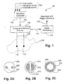
- Fig. 1 shows a detection system 100 in which waveform generator 102 is used to form signals 104 for use in impedance measurements of the surface of human tissue 120.
- the waveform generator 102 is preferably controllable independently in terms of each of time, frequency and amplitude by way of control inputs 122.
- the signals 104 are provided to driving and sensing circuitry 106 which couples the signals to a pair of leads 108, at the ends of which are electrodes 110 and 112 respectively.
- the electrodes 110, 112 are contacted to the tissue surface 120 in such a fashion that the driving and sensing circuitry 106 can obtain measurements 114 related to the response of the signals 104 in the tissue surface 120.
- a multiplexer may be coupled between the electrodes and the driving and sensing circuitry 106 to distribute the stimulus signals and accept the responses from the electrodes.
- the response signal 114 is then processed in a signal processing arrangement 116 to extract magnitude and phase information 118 relating to the impedance of the tissue surface 120.
- the magnitude and phase information 118 is preferably logged to a computer or microprocessor-based system, such as the system 400 of Fig. 4, for tissue type recognition analysis.
- Such analysis of the magnitude and phase information 118 may be implemented using software, such as an application program executing within the computer system 400.
- the processing steps may be effected by instructions in the software that are carried out by the computer system 400.
- the instructions may be formed as one or more code modules, each for performing one or more particular tasks.
- the software may also be divided into two separate parts, in which a first part performs the tissue recognition methods and a second part manages a user interface between the first part and the user.
- the software may be stored in a computer readable medium, including the storage devices described below, for example.
- the software is loaded into the computer system 400 from the computer readable medium, and then executed by the computer.
- a computer readable medium having such software or computer program recorded on it is a computer program product.
- the use of the computer program product in the computer system 400 preferably effects an advantageous apparatus for tissue-type recognition.
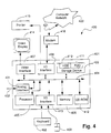
- the computer system 400 is formed by a computer module 401, input devices such as a keyboard 402 and mouse 403, and output devices including a printer 415 and a display device 414.
- a Modulator-Demodulator (Modem) transceiver device 416 is used by the computer module 401 for communicating to and from a communications network 420, for example connectable via a telephone line 421 or other functional medium.
- the modem 416 can be used to obtain access to the Internet, and other network systems, such as a Local Area Network (LAN) or a Wide Area Network (WAN).
- LAN Local Area Network
- WAN Wide Area Network
- the computer module 401 typically includes at least one processor unit 405, a memory unit 406, for example formed from semiconductor random access memory (RAM) and read only memory (ROM), input/output (I/O) interfaces including a video interface 407, and an I/O interface 413 for the keyboard 402 and mouse 403, and an interface 408 for the modem 416.
- a storage device 409 is provided and typically includes a hard disk drive 410 and a floppy disk drive 411.
- a magnetic tape drive (not illustrated) may also be used.
- a CD-ROM drive 412 is typically provided as a non-volatile source of data.
- the components 405 to 413 of the computer module 401 typically communicate via an interconnected bus 404 and in a manner which results in a conventional mode of operation of the computer system 400 known to those in the relevant art.
- Examples of computer systems on which the described arrangements can be practised include IBM-PC's and compatibles, Sun Sparcstations or alike computer systems evolved therefrom. Other computers may also be used.
- the application program is resident on the hard disk drive 410 and read and controlled in its execution by the processor 405. Intermediate storage of the program and any data fetched from the network 420 may be accomplished using the semiconductor memory 406, possibly in concert with the hard disk drive 410. In some instances, the application program may be supplied to the user encoded on a CD-ROM or floppy disk and read via the corresponding drive 412 or 411, or alternatively may be read by the user from the network 420 via the modem device 416. Still further, the software can also be loaded into the computer system 400 from other computer readable media.
- the term "computer readable medium” as used herein refers to any storage or transmission medium that participates in providing instructions and/or data to the computer system 400 for execution and/or processing.
- Examples of storage media include floppy disks, magnetic tape, CD-ROM, a hard disk drive, a ROM or integrated circuit, a magneto-optical disk, or a computer readable card such as a PCMCIA card and the like, whether or not such devices are internal or external of the computer module 401.
- Examples of transmission media include radio or infra-red transmission channels as well as a network connection to another computer or networked device, and the Internet or Intranets including e-mail transmissions and information recorded on Websites and the like.
- tissue-type recognition processes may alternatively be implemented in dedicated hardware such as one or more integrated circuits performing appropriate functions or sub functions.
- dedicated hardware may include graphic processors, digital signal processors, or one or more microprocessors and associated memories.
- the magnitude and phase information 118 may be supplied to the computer system 400 by way of the computer network 420, where the signal processing arrangement 116 has capacity to provide an appropriate output to such a network.
- the signal processing arrangement 116 may couple to an analogue interface 431 of the computer module 401 where the magnitude and phase information 118 is provided to an input 432 of the interface 431.
- the analogue interface 431 may then operate to convert the magnitude and phase information 118 into a digital form able to be processed by the computer module 401.
- the presentation of the magnitude and phase information 118 to the computer module 401 provides for storage of the raw measured data using the storage device 409 and also for the processing of that information and the storage of subsequent processed results.
- the electrodes 110 and 112 are positioned on the tissue 120, and the electrical impedance and phase response are then determined over a range of frequencies established by the waveform generator 102.
- a multiplexer again may be used where multiple pairs of electrodes are used. From this data, the values of equivalent resistance and capacitance of the electrode system formed by the leads 108, electrodes 110 and 112, and tissue 120, can be determined. This data is obtained using established electronic techniques.
- the electrode system incorporating the leads 108, and electrodes 110 and 112 is formed by an arrangement of bipolar electrodes in which the same electrodes that are used to apply energy to the tissue 120 are also used to measure the impedance of the tissue 120. Such an arrangement is used to focus on the influence of the tissue surface layers on the data that is gathered, as compared to the response of the electrodes themselves, which may be considered complementary for each of application and sensing.
- impedance measurements of cervical tissue are able, on average, to distinguish amongst many different tissue types that can be present.
- squamous tissue has a high impedance
- columnar has low impedance
- cancerous tissue is of mid-range impedance.
- the spread in these measurements is such as to render the technique of merely determining impedance as having no value as a screening tool for cervical cancer. Such has been verified by a number of independent sources.
- a preferred implementation of the electrode assembly incorporating the leads 108 and electrodes 110 and 112 comprises a probe arrangement specifically configured for the detection of cervical cancers.
- a probe may be sized and shaped similar to a writing pen and is configured with the electrode arranged at the tip of the probe whereby the probe may be moved to engage the surface of the cervix in an attempt to detect pre-cancerous and cancerous tissue.
- Fig. 2A shows a simple probe tip 200 of such a device in which a pair of electrodes 202 and 204 are arranged. As seen, the electrodes 202 and 204 are each circular in shape and are typically spaced apart by approximately 2mm, thereby giving the probe tip 200 as having an overall diameter of approximately 5-7mm.
- a probe tip 210 includes two semi-circular shape electrodes 212 and 214 which are separated by a distance 216, again of approximately 2mm.
- a distance 216 again of approximately 2mm.
- FIG. 2C An further alternate arrangement is shown in Fig. 2C which incorporates a three electrode configuration that is also operable in the "bipolar" manner described above.
- an electrode tip 220 is shown having three electrodes 222, 224 and 228 each occupying approximately one third of an arc of an annulus defined substantially by the diameter of the probe tip 220.
- any two of the electrodes 222, 224 and 228 or paired combination such as one electrode with respect to the other two electrodes, may be used to provide and detect a stimulus.
- samples may be made by alternating the reference electrode thereby providing for each of the electrodes 222, 224 and 228 to be used as each of a driving electrode and for a different sample, a reference electrode.
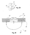
- Fig. 2D shows a transverse cross sectional representation of a further electrode tip 230 specifically adapted for detecting cervical cancers.
- the probe tip 230 includes a mounting portion 232 by which a coupling wand may be connected to convey electrode leads and to provide for resilience support as the probe 230 is engaged with the cervix.
- the probe includes a tip having a circular surface having a concave portion 234 formed as an annulus about a central elongate portion 236.
- the probe tip 230 may be engaged with the cervix such that the central extension 236 may enter the birth canal to enable detection of pre-cancerous and cancerous tissues within the birth canal which would not ordinarily be detected by exterior probing.
- Electrodes 238 Arranged across the curved surface of the probe tip 230 that engages the cervix are a number of electrodes 238 arranged in a fashion corresponding to or similar to the electrodes of Fig. 2A, and which may be activated and sensed in a bipolar sequence to obtain impedance measurements from various portions of the cervical surface.
- Fig. 2E schematically illustrates the typical conduction process performed in the impedance measurements described herein.
- an arrangement 250 of electrodes 252 and 254 are contacted against a patient's tissue 256.
- the tissue 256 may be construed as having a surface component 260 and a bulk component 258.
- the surface component 260 can vary in size from about 1 micrometre (ie. that of only a few tissue cells), up to something like about 100 micrometres. With an electrode spacing of approximately 2mm as illustrated, the surface component 260 thus represents a very small boundary between the electrodes 252 and 254, and the bulk tissue 258.
- the response of the surface portion 260 that is important, and not that of the bulk tissue type 258.
- the form of interaction between the electrodes 252 and 254 and the surface 260 substantially influences the reliability of measurements obtained and, as a consequence, the determination of any tissue types detected.
- the electrode configurations that may be used depend upon the form of tissue being diagnosed. For example, with cervical tissue, the above described arrangements may be used. This allows the electrodes to be placed upon the cervix through an aperture provided by a speculum that is used to open the vagina. Other electrode configurations may also be used.
- the electrodes are usually positioned on the outer wall of a cylindrical probe. Pressure is exerted during use of the probe to ensure that the electrodes make adequate contact with the walls. Other configurations may be used.
- measuring circuit employed may comprise the measurement of the electrical properties between pairs or groups of electrodes.
- Other configurations may entail measurement between one electrode and several others that are in contact with the tissue being measured.
- a separate reference electrode may be placed on the patient in a convenient area and measurements made between the reference electrode and other electrodes that are in the tissue being diagnosed.
- the size and spacing of electrodes will have effects with regards to the bulk tissue impedance measured. In this regard, the current from large, widely spaced electrodes is more likely to follow a path through deeper (low impedance) tissue, such as the tissue 258, than would the source current from small, closely spaced electrodes.
- the material of the electrodes can be metallic or some other conductor such as conductive polymers.
- the surface electrode chemistry of the electrodes needs to be predictable so that reproducible data is obtained on the various tissue types.
- the composition of the electrodes must be such as to not present dangers to the patient. Some metals and polymers may lead to irritation of the tissue and thus need to be avoided. Suitable biocompatible materials are generally available. Gold satisfies these requirements and is a preferred material for the electrodes described above.
- the signal processing arrangement 116 can be implemented using an impedance spectrum analyser widely available in the art.
- the system 100 as with other medical devices must provide for electrical safety for the patient. Isolation circuitry is thus necessary in each of the components of the system 100 until a stage can be configured whereby patient isolation and safety can be ensured.
- Data from the system 100 is typically analysed by a computer since the relationship between any one measured parameter and the type or health of the tissue is not simple.
- the general purpose computer configuration of Fig. 4 thus may be used.
- the computer for system 400 is interfaced with the spectrum analyser (forming the signal processing arrangement 116) to thereby provide an output via the video display 414 or printer 415 to inform a user of the results of the impedance computations.
- a stand-alone digital signal processing (DSP) system having a corresponding operable functionality, may be used.
- Algorithms used by the computer 400 for assessing the magnitude and phase information 118 are derived from data gathered using the same or equivalent devices for measuring tissue. That data is extracted from known tissue types and is gathered and used to derive suitable equations to provide the various diagnoses.
- the diagnoses that are used to characterise the type or health of the tissue may be one of several or may be combinations of methods. In the case of cervical tissue, the available methods of diagnosis includes cytology, hystology, and colposcopy, which often do not agree with each other. Similar ranges of tools are available for other tissue groupings. Further, the various methods of diagnoses described herein may become part of a broader repertoire of methods of tissue analysis given that such do not require intervention of a human interpreter to arrive at results.
- phase data can be employed to underpin the impedance data and to significantly raise the reliability of the diagnosis. It has been found by the present inventors that over the frequency range of 200 Hz to 200,000 Hz, the phase response when using gold electrodes of area 2 square millimetres, distinguishes reliably amongst the three dominant tissue types. At mid-range (on a logarithmic scale) frequencies, the phase response are as follows:
- tissue types displayed parameters according to Table 1 below: Tissue Type Magnitude of Impedance at 5kHz Magnitude of Impedance at 10kHz Ratio of phases 5kHz /10kHz Squamous 7000 5000 0.88 Pre-cancerous 2000 1700 1 Columnar 800 700 1.25
- phase ratios indicated in Table 1 remain substantially constant even if the electrode capacitance is changed by significant amounts, such as ⁇ 20%. This was because the phase was measured in a region of constant phase slope for each tissue type. This region extends beyond the measurement points by at least 20% in frequency. A change in electrode capacitance caused by protein absorption only shifted the frequency axis and did not change the slope of the phase in the range specified. Hence, the present inventors determined that it is important to choose measuring frequencies at which the slope of the phase is substantially constant, for the calculation of the phase ratio.
- high grade cancerous tissue has an impedance magnitude lying between the typical cervical tissue types such as columnar and squamous, both of which are normal tissue types.
- columnar tissue is mucosal and in many respects is representative of or associated with bodily fluids encountered in the cervical region.
- Squamous tissue on the other hand is substantially skin-like. Each of these are normal tissue types and quite distinct from high grade cancerous tissue.
- multiple types of measurements may be additionally used to improve the discrimination between tissue-types.
- absolute magnitude and phase may be combined with other variables.
- other forms of processing may be used to determine useful reference magnitudes and phase of impedance for tissue types and certain frequencies. For example, curve fitting may be applied to best match a spread of sample data.
- the impedances fall into a pattern that is related to the mucosa] qualities of the tissue.
- the phase changes in slope from negative to positive, the pre-cancerous tissue shows a fairly constant phase over the frequency range of interest.
- the average values of the impedance magnitude of Fig. 3A of all of these quantities is diagnostic, such values can vary considerably in that they possess a relatively large amount of noise.
- a consideration of both magnitude and phase provides, according to the present disclosure, for a minimisation in errors in diagnoses.
- Errors in measurements can be ameliorated by the taking of multiple impedance samples at each of the various frequencies prior to obtaining an average value for that frequency. At least two frequencies such as 5kHz and 10kHz should be used, although measurements over the broader range, as illustrated in Figs. 3A and 3B provide for substantial improvements in accuracy. As seen from Fig. 3B, frequencies in the band from about 3kHz to about 12kHz characterise substantially linear portions of each of the phase plots. For a detailed result, a swept continuous frequency may be used enabling the accurate plotting of the phase change over swept frequency range, as illustrated in Figs. 3A and 3B. It is to be noted that the frequencies used in Figs.
- 3A and 3B are statistically applicable to cervical cancers and that other frequency bands or specific frequencies may be shown to be diagnostic for other types of tissue.
- An advantage in measuring at only a few (eg. 2) frequencies is that such measurements are faster, and can be processed faster, thereby enabling measurements from multiple electrode pairs within an acceptable time frame.
- Fig. 3C shows a plot of the real and imaginary parts of the complex impedance determined from the sample data of Table 2 and Table 3, used to construct the plots of Figs. 3A and 3B.
- the plots of Fig. 3C include markers on each trace to indicate the frequency band of 3.5kHz to 10kHz. This alternative view of the impedance data also holds possibilities for tissue-type discrimination.
- the sections of the curves in the 3,5-10kHz range display different gradient and spatial characteristics.
- Fig. 3A in respect of the calibration "tissue" (ie. saline solution), is highly indicative of the capacitive effects of the electrodes whereby the impedance declines progressively with frequency. At higher frequencies, the resistance dominates the impedance and thus the magnitude stops decreasing with frequency. This is seen from the calibration curve in Fig. 3A to occur at approximately 8kHz where there is an apparent change in slope of the curve. At lower frequencies (eg. 300Hz -1kHz) the measured impedance is affected by the capacitive effects of the electrodes.
- tissue ie. saline solution
- the measurements of impedance noted above may be obtained using a constant amplitude stimulus signal 104.
- the arrangements may be further enhanced by measuring the pulse response of the tissue in order to determine frequency and phase components in response to pulses.
- the waveform generator 102 may output a series of pulses. Measurements using a time-domain or pulse response are described in US Patent Nos, 5,800,350 and 6,026,323. Using measurements made via a pulse technique enables the system 100 to characterise the electrodes so that corrections may be made to measured impedance data. In the same manner, measurements made using a spectrum analyser approach described above can be used to improve the quality of the pulse data. Such further reduces uncertainties in respect of the diagnosis.
- the time domain approach as described in US Patent No. 5,800,350 involves stimulating the tissue with a voltage pulse and measuring the current flowing into the patient during the pulse and the decay of the tissue voltage after the pulse. This technique is sensitive to variations in the parametric performance of the electrodes and time domain analysis techniques discussed below have been developed to reduce the effect of the electrode parametric variation.
- the time domain technique involves using the time constants of the end of the current and voltage curve to obtain an estimate for the electrode capacitance. This estimate can then be used to correct for variations in the decay curves due to electrode capacitance variations.
- a time constant of 200 ⁇ s was found and resulted from the electrode size, and the probe input impedance.
- Figs. 5A and 5B show a voltage curve and current curve respectively.
- Application of the voltage pulse leads to current flowing into the patient. Initially the current curve is dominated by current charging up the tissue capacitance. However the tail of the current curve is dominated by residual charging of the electrodes through the resistance of the patient. Likewise, after the pulse, the voltage curve decays with the initial 200 ⁇ s of the curve affected by the tissue capacitance and electrode capacitance. By the tail of the voltage curve (after 200 ⁇ s for our electrodes and input resistance) the decay time constant is dominated by the electrode capacitance. Thus the decay displays a double-layer effect influenced by two capacitances.
- the electrode capacitance calculated in this way has shown to be sensitive to production variation in the electrodes, while at the same time retaining some residual tissue discrimination due to its sensitivity to the surface of the tissue.
- techniques were developed to normalise out (ie. nullify) production variation while at the same time retaining the tissue discrimination. This was done by performing measurements in standard saline solution prior to measurements on tissue and using the electrode capacitance calculated from the saline measurements to derive a correction factor for the tissue decay curves.
- Vdecay_norm(t) Vamp_norm ( Vdecay ( t ) Vdecay ( tref ) ) norm
- the amplitude normalisation time point ( tref ) is chosen to occur after the decay in the tissue response has reached zero but before the electrodes have fully decayed. This is around 300 ⁇ s in the system described herein.
- the electrode impedance is a linear capacitance.
- Equation 5 ⁇ determines the distribution of time constants in the voltage decay waveform. For a linear capacitor, ⁇ is equal to one and there is only one time constant which is constant during the voltage decay. For other values of ⁇ , the effective time constant increases with time during the voltage decay.
- the value for ⁇ can be measured using impedance sweep data using techniques known to those skilled in the art. In this fashion, an impedance measured using the swept frequency technique can be used to provide correction factors for the time domain analysis.
- the present inventors have determined that this technique will substantially and reliably remove the effect of the production variation in the decay curves while at the same time retain the tissue discrimination provided by the electrode capacitance measured on the tissue.
- the measurements in saline can occur either during production test or just prior to electrode use.
Landscapes
- Health & Medical Sciences (AREA)
- Life Sciences & Earth Sciences (AREA)
- Biomedical Technology (AREA)
- Molecular Biology (AREA)
- Radiology & Medical Imaging (AREA)
- Biophysics (AREA)
- Pathology (AREA)
- Engineering & Computer Science (AREA)
- Nuclear Medicine, Radiotherapy & Molecular Imaging (AREA)
- Heart & Thoracic Surgery (AREA)
- Medical Informatics (AREA)
- Physics & Mathematics (AREA)
- Surgery (AREA)
- Animal Behavior & Ethology (AREA)
- General Health & Medical Sciences (AREA)
- Public Health (AREA)
- Veterinary Medicine (AREA)
- Investigating Or Analyzing Materials By The Use Of Electric Means (AREA)
- Measurement And Recording Of Electrical Phenomena And Electrical Characteristics Of The Living Body (AREA)
Applications Claiming Priority (2)
| Application Number | Priority Date | Filing Date | Title |
|---|---|---|---|
| AUPR571801 | 2001-06-15 | ||
| AUPR5718A AUPR571801A0 (en) | 2001-06-15 | 2001-06-15 | Apparatus for tissue type recognition using multiple measurement techniques |
Publications (2)
| Publication Number | Publication Date |
|---|---|
| EP1266612A2 true EP1266612A2 (de) | 2002-12-18 |
| EP1266612A3 EP1266612A3 (de) | 2003-01-29 |
Family
ID=3829691
Family Applications (1)
| Application Number | Title | Priority Date | Filing Date |
|---|---|---|---|
| EP02254165A Withdrawn EP1266612A3 (de) | 2001-06-15 | 2002-06-14 | Vorrichtung zur Gewebeerkennung mittels mehrerer Messtechniken |
Country Status (3)
| Country | Link |
|---|---|
| US (1) | US6723049B2 (de) |
| EP (1) | EP1266612A3 (de) |
| AU (1) | AUPR571801A0 (de) |
Cited By (4)
| Publication number | Priority date | Publication date | Assignee | Title |
|---|---|---|---|---|
| EP1563789A1 (de) * | 2004-02-17 | 2005-08-17 | Instrumentarium Corporation | Überwachung des neurologischen Zustands eines Patienten |
| WO2007075091A3 (en) * | 2005-12-29 | 2007-08-30 | Rikshospitalet Radiumhospitale | Method and apparatus for determining local tissue impedance for positioning of a needle |
| WO2016055666A1 (en) * | 2014-10-10 | 2016-04-14 | Oslo Universitetssykehus Hf | Determining biological tissue type |
| EP3335794A1 (de) * | 2016-12-13 | 2018-06-20 | DBS System SA | Vorrichtung und verfahren zum feststellen der ablagerung von einer biologischen flüssigkeitsprobe auf einem substrat |
Families Citing this family (72)
| Publication number | Priority date | Publication date | Assignee | Title |
|---|---|---|---|---|
| AUPQ113799A0 (en) | 1999-06-22 | 1999-07-15 | University Of Queensland, The | A method and device for measuring lymphoedema |
| WO2004047643A1 (en) * | 2002-11-27 | 2004-06-10 | Z-Tech (Canada) Inc. | Bioimpedance measurement using controller-switched current injection and multiplexer selected electrode connection |
| US8060195B2 (en) * | 2003-05-02 | 2011-11-15 | The Johns Hopkins University | Devices, systems and methods for bioimpedance measurement of cervical tissue and methods for diagnosis and treatment of human cervix |
| KR100580629B1 (ko) * | 2003-11-17 | 2006-05-16 | 삼성전자주식회사 | 고주파 대역의 피부 임피던스 응답을 표현하는 피부임피던스 모델 |
| CA2578106C (en) | 2004-06-18 | 2015-09-01 | The University Of Queensland | Oedema detection |
| US8430881B2 (en) | 2004-10-15 | 2013-04-30 | Baxano, Inc. | Mechanical tissue modification devices and methods |
| US7738968B2 (en) | 2004-10-15 | 2010-06-15 | Baxano, Inc. | Devices and methods for selective surgical removal of tissue |
| US8257356B2 (en) | 2004-10-15 | 2012-09-04 | Baxano, Inc. | Guidewire exchange systems to treat spinal stenosis |
| US7857813B2 (en) | 2006-08-29 | 2010-12-28 | Baxano, Inc. | Tissue access guidewire system and method |
| US20110190772A1 (en) | 2004-10-15 | 2011-08-04 | Vahid Saadat | Powered tissue modification devices and methods |
| US7959577B2 (en) | 2007-09-06 | 2011-06-14 | Baxano, Inc. | Method, system, and apparatus for neural localization |
| US7887538B2 (en) | 2005-10-15 | 2011-02-15 | Baxano, Inc. | Methods and apparatus for tissue modification |
| US7578819B2 (en) | 2005-05-16 | 2009-08-25 | Baxano, Inc. | Spinal access and neural localization |
| US9101386B2 (en) | 2004-10-15 | 2015-08-11 | Amendia, Inc. | Devices and methods for treating tissue |
| US20100331883A1 (en) | 2004-10-15 | 2010-12-30 | Schmitz Gregory P | Access and tissue modification systems and methods |
| US8062300B2 (en) | 2006-05-04 | 2011-11-22 | Baxano, Inc. | Tissue removal with at least partially flexible devices |
| US7938830B2 (en) | 2004-10-15 | 2011-05-10 | Baxano, Inc. | Powered tissue modification devices and methods |
| US8617163B2 (en) | 2004-10-15 | 2013-12-31 | Baxano Surgical, Inc. | Methods, systems and devices for carpal tunnel release |
| US7738969B2 (en) | 2004-10-15 | 2010-06-15 | Baxano, Inc. | Devices and methods for selective surgical removal of tissue |
| AU2005295589B2 (en) | 2004-10-15 | 2009-12-03 | Baxano, Inc. | Devices and methods for tissue removal |
| US8048080B2 (en) | 2004-10-15 | 2011-11-01 | Baxano, Inc. | Flexible tissue rasp |
| US9247952B2 (en) | 2004-10-15 | 2016-02-02 | Amendia, Inc. | Devices and methods for tissue access |
| US8221397B2 (en) | 2004-10-15 | 2012-07-17 | Baxano, Inc. | Devices and methods for tissue modification |
| US8103337B2 (en) | 2004-11-26 | 2012-01-24 | Impedimed Limited | Weighted gradient method and system for diagnosing disease |
| CA2608962C (en) * | 2005-07-01 | 2016-12-06 | Scott Chetham | Monitoring system |
| AU2006265763B2 (en) * | 2005-07-01 | 2012-08-09 | Impedimed Limited | Monitoring system |
| EP1912563B1 (de) * | 2005-08-02 | 2016-04-20 | Impedimed Limited | Impedanzparameter-werte |
| WO2007041783A1 (en) | 2005-10-11 | 2007-04-19 | Impedance Cardiology Systems, Inc. | Hydration status monitoring |
| US8092456B2 (en) | 2005-10-15 | 2012-01-10 | Baxano, Inc. | Multiple pathways for spinal nerve root decompression from a single access point |
| US8062298B2 (en) | 2005-10-15 | 2011-11-22 | Baxano, Inc. | Flexible tissue removal devices and methods |
| US8366712B2 (en) | 2005-10-15 | 2013-02-05 | Baxano, Inc. | Multiple pathways for spinal nerve root decompression from a single access point |
| US8603084B2 (en) | 2005-12-06 | 2013-12-10 | St. Jude Medical, Atrial Fibrillation Division, Inc. | System and method for assessing the formation of a lesion in tissue |
| US8406866B2 (en) | 2005-12-06 | 2013-03-26 | St. Jude Medical, Atrial Fibrillation Division, Inc. | System and method for assessing coupling between an electrode and tissue |
| US9492226B2 (en) * | 2005-12-06 | 2016-11-15 | St. Jude Medical, Atrial Fibrillation Division, Inc. | Graphical user interface for real-time RF lesion depth display |
| US9254163B2 (en) | 2005-12-06 | 2016-02-09 | St. Jude Medical, Atrial Fibrillation Division, Inc. | Assessment of electrode coupling for tissue ablation |
| US10362959B2 (en) | 2005-12-06 | 2019-07-30 | St. Jude Medical, Atrial Fibrillation Division, Inc. | System and method for assessing the proximity of an electrode to tissue in a body |
| US8369922B2 (en) | 2005-12-06 | 2013-02-05 | St. Jude Medical Atrial Fibrillation Division, Inc. | Method for displaying catheter electrode-tissue contact in electro-anatomic mapping and navigation system |
| WO2007070361A2 (en) | 2005-12-06 | 2007-06-21 | St. Jude Medical, Atrial Fibrillation Division, Inc. | Assessment of electrode coupling for tissue ablation |
| US8403925B2 (en) | 2006-12-06 | 2013-03-26 | St. Jude Medical, Atrial Fibrillation Division, Inc. | System and method for assessing lesions in tissue |
| JP5431147B2 (ja) | 2006-05-30 | 2014-03-05 | インぺディメッド リミテッド | インピーダンス測定 |
| CA2670293C (en) | 2006-11-30 | 2017-01-03 | Impedimed Limited | Measurement apparatus |
| US20080171950A1 (en) * | 2006-12-18 | 2008-07-17 | Genisent International Inc. | Systems and methods for a pregnancy monitoring device |
| WO2008086565A1 (en) * | 2007-01-15 | 2008-07-24 | Impedimed Limited | Monitoring system |
| US8487686B2 (en) * | 2007-03-30 | 2013-07-16 | Impedimed Limited | Active guarding for reduction of resistive and capacitive signal loading with adjustable control of compensation level |
| EP2148613B9 (de) | 2007-04-20 | 2014-12-10 | Impedimed Limited | Überwachungssystem und sonde |
| EP2211714B1 (de) * | 2007-11-05 | 2016-11-23 | Impedimed Limited | Nachweis der impedanz |
| US8192436B2 (en) | 2007-12-07 | 2012-06-05 | Baxano, Inc. | Tissue modification devices |
| US8290578B2 (en) | 2007-12-28 | 2012-10-16 | St. Jude Medical, Atrial Fibrillation Division, Inc. | Method and apparatus for complex impedance compensation |
| US9204927B2 (en) | 2009-05-13 | 2015-12-08 | St. Jude Medical, Atrial Fibrillation Division, Inc. | System and method for presenting information representative of lesion formation in tissue during an ablation procedure |
| US20110264000A1 (en) * | 2007-12-28 | 2011-10-27 | Saurav Paul | System and method for determining tissue type and mapping tissue morphology |
| AU2008207672B2 (en) | 2008-02-15 | 2013-10-31 | Impedimed Limited | Impedance Analysis |
| WO2010009093A2 (en) | 2008-07-14 | 2010-01-21 | Baxano, Inc | Tissue modification devices |
| US8398641B2 (en) | 2008-07-01 | 2013-03-19 | Baxano, Inc. | Tissue modification devices and methods |
| US9314253B2 (en) | 2008-07-01 | 2016-04-19 | Amendia, Inc. | Tissue modification devices and methods |
| US8409206B2 (en) | 2008-07-01 | 2013-04-02 | Baxano, Inc. | Tissue modification devices and methods |
| WO2010048402A2 (en) | 2008-10-22 | 2010-04-29 | Cornell University | Method and device for evaluation of local tissue's biological or biomechanical character |
| EP2348987B1 (de) | 2008-11-28 | 2017-03-22 | Impedimed Limited | Impedanz-messverfahren |
| US20100191141A1 (en) * | 2009-01-27 | 2010-07-29 | Peter Aberg | Method and apparatus for diagnosing a diseased condition in tissue of a subject |
| EP2405823A4 (de) | 2009-03-13 | 2012-07-04 | Baxano Inc | Vorrichtungen und verfahren für flexible nervenortung |
| US8700789B2 (en) * | 2009-03-16 | 2014-04-15 | Apple Inc. | Accessory and mobile computing device communication using an application communication protocol |
| US8394102B2 (en) | 2009-06-25 | 2013-03-12 | Baxano, Inc. | Surgical tools for treatment of spinal stenosis |
| WO2011050393A1 (en) | 2009-10-26 | 2011-05-05 | Impedimed Limited | Fluid level indicator determination |
| WO2011060497A1 (en) | 2009-11-18 | 2011-05-26 | Impedimed Limited | Signal distribution for patient-electrode measurements |
| US20120323134A1 (en) * | 2011-02-28 | 2012-12-20 | Nervonix, Inc. | Method and system for determining a location of nerve tissue in three-dimensional space |
| US10413349B2 (en) | 2011-03-04 | 2019-09-17 | Covidien Lp | System and methods for identifying tissue and vessels |
| US8892198B2 (en) | 2011-04-28 | 2014-11-18 | Skulpt, Inc. | Devices and methods for evaluating tissue |
| US9861293B2 (en) | 2011-04-28 | 2018-01-09 | Myolex Inc. | Sensors, including disposable sensors, for measuring tissue |
| WO2012151493A2 (en) * | 2011-05-04 | 2012-11-08 | The University Of Akron | Variable-frequency stimulator for electrosurgery |
| US9351649B2 (en) * | 2012-02-21 | 2016-05-31 | Xerox Corporation | System and method for determining video-based pulse transit time with time-series signals |
| US11039756B2 (en) | 2017-04-12 | 2021-06-22 | Onko Solutions Llc | Functional disposable sheath |
| US20220022771A1 (en) * | 2020-10-03 | 2022-01-27 | Nano Hesgarsazan Salamat Arya | Electrical impedance spectroscopy for evaluation of excision-required suspicious masses |
| US20220015660A1 (en) * | 2020-10-03 | 2022-01-20 | Nano Hesgarsazan Salamat Arya | Bioelectrical cancer diagnosis of margins of a freshly dissected cancerous tumor |
Citations (2)
| Publication number | Priority date | Publication date | Assignee | Title |
|---|---|---|---|---|
| US5800350A (en) | 1993-11-01 | 1998-09-01 | Polartechnics, Limited | Apparatus for tissue type recognition |
| US6026323A (en) | 1997-03-20 | 2000-02-15 | Polartechnics Limited | Tissue diagnostic system |
Family Cites Families (3)
| Publication number | Priority date | Publication date | Assignee | Title |
|---|---|---|---|---|
| US4458694A (en) * | 1977-11-02 | 1984-07-10 | Yeda Research & Development Co., Ltd. | Apparatus and method for detection of tumors in tissue |
| US5415164A (en) * | 1991-11-04 | 1995-05-16 | Biofield Corp. | Apparatus and method for screening and diagnosing trauma or disease in body tissues |
| US5454377A (en) * | 1993-10-08 | 1995-10-03 | The Ohio State University | Method for measuring the myocardial electrical impedance spectrum |
-
2001
- 2001-06-15 AU AUPR5718A patent/AUPR571801A0/en not_active Abandoned
-
2002
- 2002-06-14 US US10/172,703 patent/US6723049B2/en not_active Expired - Lifetime
- 2002-06-14 EP EP02254165A patent/EP1266612A3/de not_active Withdrawn
Patent Citations (2)
| Publication number | Priority date | Publication date | Assignee | Title |
|---|---|---|---|---|
| US5800350A (en) | 1993-11-01 | 1998-09-01 | Polartechnics, Limited | Apparatus for tissue type recognition |
| US6026323A (en) | 1997-03-20 | 2000-02-15 | Polartechnics Limited | Tissue diagnostic system |
Cited By (6)
| Publication number | Priority date | Publication date | Assignee | Title |
|---|---|---|---|---|
| EP1563789A1 (de) * | 2004-02-17 | 2005-08-17 | Instrumentarium Corporation | Überwachung des neurologischen Zustands eines Patienten |
| WO2007075091A3 (en) * | 2005-12-29 | 2007-08-30 | Rikshospitalet Radiumhospitale | Method and apparatus for determining local tissue impedance for positioning of a needle |
| WO2016055666A1 (en) * | 2014-10-10 | 2016-04-14 | Oslo Universitetssykehus Hf | Determining biological tissue type |
| JP2017529977A (ja) * | 2014-10-10 | 2017-10-12 | オスロ ユニヴェルジテットサイケフス ホーエフ | 生体組織型の決定 |
| US10716489B2 (en) | 2014-10-10 | 2020-07-21 | Oslo Universitetssykehus Hf | Determining biological tissue type |
| EP3335794A1 (de) * | 2016-12-13 | 2018-06-20 | DBS System SA | Vorrichtung und verfahren zum feststellen der ablagerung von einer biologischen flüssigkeitsprobe auf einem substrat |
Also Published As
| Publication number | Publication date |
|---|---|
| US6723049B2 (en) | 2004-04-20 |
| AUPR571801A0 (en) | 2001-07-12 |
| EP1266612A3 (de) | 2003-01-29 |
| US20030060696A1 (en) | 2003-03-27 |
Similar Documents
| Publication | Publication Date | Title |
|---|---|---|
| US6723049B2 (en) | Apparatus for tissue type recognition using multiple measurement techniques | |
| EP1460936B1 (de) | System zur untersuchung von gewebe nach seinen dielektrischen eigenschaften | |
| CN109864712B (zh) | 电阻抗成像设备和方法 | |
| US10716489B2 (en) | Determining biological tissue type | |
| US6845264B1 (en) | Apparatus for recognizing tissue types | |
| US5800350A (en) | Apparatus for tissue type recognition | |
| EP2124740B1 (de) | System zur erkennung von präkanzerogenem und kanzerogenem gewebe | |
| EP2175776B1 (de) | Impedanz-messverfahren | |
| CN102973267B (zh) | 利用多种测量技术识别组织类别的装置 | |
| AU2020314838B2 (en) | System and method for measuring tissue parameters by use of capacitive tactile sensor | |
| US11617518B2 (en) | Method for detecting both pre-cancerous and cancerous tissues | |
| JP2011505169A (ja) | 電気インピーダンス測定に基づいた肝脂肪症の診断およびモニター装置 | |
| KR102241685B1 (ko) | 피부 질환 진단 장치 및 시스템 | |
| Luo et al. | In vivo muscle conduction study of the tongue using a multi-electrode tongue depressor | |
| AU785174B2 (en) | Apparatus for tissue type recognition using multiple measurement techniques | |
| Amin et al. | Modelling and characterization of cell abnormality using electrical impedance spectroscopy (EIS) system for the preliminary analysis to predict breast cancer | |
| EP3651641B1 (de) | System zur messung der elektrischen impedanz in menschlichen geweben | |
| JP3182601B2 (ja) | 組織タイプ認識方法およびそのための装置 | |
| KR101431011B1 (ko) | 전자기파와 캐비티 공진을 이용한 유전체 공진기, 이를 이용한 혈당 측정 장치 및 방법 | |
| KR100688355B1 (ko) | 신체내의 병소를 검출하는 장치 및 방법 | |
| CN120570584B (zh) | 一种环咽肌导管球囊扩张术实时监测方法及装置 | |
| Emran | Novel bioimpedance spectroscopic methods for examination of oral mucosal tissues | |
| HK1069967B (en) | System for examining tissue according to the dielectric properties thereof | |
| HK1013943B (en) | Apparatus for diseased tissue type recognition |
Legal Events
| Date | Code | Title | Description |
|---|---|---|---|
| PUAI | Public reference made under article 153(3) epc to a published international application that has entered the european phase |
Free format text: ORIGINAL CODE: 0009012 |
|
| PUAL | Search report despatched |
Free format text: ORIGINAL CODE: 0009013 |
|
| AK | Designated contracting states |
Kind code of ref document: A2 Designated state(s): AT BE CH CY DE DK ES FI FR GB GR IE IT LI LU MC NL PT SE TR |
|
| AX | Request for extension of the european patent |
Free format text: AL;LT;LV;MK;RO;SI |
|
| AK | Designated contracting states |
Designated state(s): AT BE CH CY DE DK ES FI FR GB GR IE IT LI LU MC NL PT SE TR |
|
| AX | Request for extension of the european patent |
Extension state: AL LT LV MK RO SI |
|
| AKX | Designation fees paid | ||
| REG | Reference to a national code |
Ref country code: DE Ref legal event code: 8566 |
|
| STAA | Information on the status of an ep patent application or granted ep patent |
Free format text: STATUS: THE APPLICATION IS DEEMED TO BE WITHDRAWN |
|
| 18D | Application deemed to be withdrawn |
Effective date: 20030730 |