EP1266779A2 - Fahrzeug-Kühlkreislauf für die Kühlung einer temperaturerhöhenden Einrichtung mittels eines Kuhlmittels - Google Patents
Fahrzeug-Kühlkreislauf für die Kühlung einer temperaturerhöhenden Einrichtung mittels eines Kuhlmittels Download PDFInfo
- Publication number
- EP1266779A2 EP1266779A2 EP02006436A EP02006436A EP1266779A2 EP 1266779 A2 EP1266779 A2 EP 1266779A2 EP 02006436 A EP02006436 A EP 02006436A EP 02006436 A EP02006436 A EP 02006436A EP 1266779 A2 EP1266779 A2 EP 1266779A2
- Authority
- EP
- European Patent Office
- Prior art keywords
- coolant
- cooling
- cooler
- heat exchanger
- circuit
- Prior art date
- Legal status (The legal status is an assumption and is not a legal conclusion. Google has not performed a legal analysis and makes no representation as to the accuracy of the status listed.)
- Granted
Links
Images


Classifications
-
- B—PERFORMING OPERATIONS; TRANSPORTING
- B60—VEHICLES IN GENERAL
- B60H—ARRANGEMENTS OF HEATING, COOLING, VENTILATING OR OTHER AIR-TREATING DEVICES SPECIALLY ADAPTED FOR PASSENGER OR GOODS SPACES OF VEHICLES
- B60H1/00—Heating, cooling or ventilating devices
- B60H1/00642—Control systems or circuits; Control members or indication devices for heating, cooling or ventilating devices
- B60H1/00814—Control systems or circuits characterised by their output, for controlling particular components of the heating, cooling or ventilating installation
- B60H1/00878—Control systems or circuits characterised by their output, for controlling particular components of the heating, cooling or ventilating installation the components being temperature regulating devices
- B60H1/00885—Controlling the flow of heating or cooling liquid, e.g. valves or pumps
-
- B—PERFORMING OPERATIONS; TRANSPORTING
- B60—VEHICLES IN GENERAL
- B60H—ARRANGEMENTS OF HEATING, COOLING, VENTILATING OR OTHER AIR-TREATING DEVICES SPECIALLY ADAPTED FOR PASSENGER OR GOODS SPACES OF VEHICLES
- B60H1/00—Heating, cooling or ventilating devices
- B60H1/00271—HVAC devices specially adapted for particular vehicle parts or components and being connected to the vehicle HVAC unit
-
- F—MECHANICAL ENGINEERING; LIGHTING; HEATING; WEAPONS; BLASTING
- F01—MACHINES OR ENGINES IN GENERAL; ENGINE PLANTS IN GENERAL; STEAM ENGINES
- F01P—COOLING OF MACHINES OR ENGINES IN GENERAL; COOLING OF INTERNAL-COMBUSTION ENGINES
- F01P9/00—Cooling having pertinent characteristics not provided for in, or of interest apart from, groups F01P1/00 - F01P7/00
- F01P9/06—Cooling having pertinent characteristics not provided for in, or of interest apart from, groups F01P1/00 - F01P7/00 by use of refrigerating apparatus, e.g. of compressor or absorber type
-
- B—PERFORMING OPERATIONS; TRANSPORTING
- B60—VEHICLES IN GENERAL
- B60H—ARRANGEMENTS OF HEATING, COOLING, VENTILATING OR OTHER AIR-TREATING DEVICES SPECIALLY ADAPTED FOR PASSENGER OR GOODS SPACES OF VEHICLES
- B60H1/00—Heating, cooling or ventilating devices
- B60H1/00271—HVAC devices specially adapted for particular vehicle parts or components and being connected to the vehicle HVAC unit
- B60H2001/00307—Component temperature regulation using a liquid flow
-
- B—PERFORMING OPERATIONS; TRANSPORTING
- B60—VEHICLES IN GENERAL
- B60H—ARRANGEMENTS OF HEATING, COOLING, VENTILATING OR OTHER AIR-TREATING DEVICES SPECIALLY ADAPTED FOR PASSENGER OR GOODS SPACES OF VEHICLES
- B60H1/00—Heating, cooling or ventilating devices
- B60H1/00642—Control systems or circuits; Control members or indication devices for heating, cooling or ventilating devices
- B60H1/00814—Control systems or circuits characterised by their output, for controlling particular components of the heating, cooling or ventilating installation
- B60H1/00878—Control systems or circuits characterised by their output, for controlling particular components of the heating, cooling or ventilating installation the components being temperature regulating devices
- B60H2001/00949—Control systems or circuits characterised by their output, for controlling particular components of the heating, cooling or ventilating installation the components being temperature regulating devices comprising additional heating/cooling sources, e.g. second evaporator
-
- F—MECHANICAL ENGINEERING; LIGHTING; HEATING; WEAPONS; BLASTING
- F01—MACHINES OR ENGINES IN GENERAL; ENGINE PLANTS IN GENERAL; STEAM ENGINES
- F01P—COOLING OF MACHINES OR ENGINES IN GENERAL; COOLING OF INTERNAL-COMBUSTION ENGINES
- F01P2050/00—Applications
- F01P2050/24—Hybrid vehicles
-
- F—MECHANICAL ENGINEERING; LIGHTING; HEATING; WEAPONS; BLASTING
- F01—MACHINES OR ENGINES IN GENERAL; ENGINE PLANTS IN GENERAL; STEAM ENGINES
- F01P—COOLING OF MACHINES OR ENGINES IN GENERAL; COOLING OF INTERNAL-COMBUSTION ENGINES
- F01P2060/00—Cooling circuits using auxiliaries
- F01P2060/08—Cabin heater
-
- F—MECHANICAL ENGINEERING; LIGHTING; HEATING; WEAPONS; BLASTING
- F01—MACHINES OR ENGINES IN GENERAL; ENGINE PLANTS IN GENERAL; STEAM ENGINES
- F01P—COOLING OF MACHINES OR ENGINES IN GENERAL; COOLING OF INTERNAL-COMBUSTION ENGINES
- F01P5/00—Pumping cooling-air or liquid coolants
- F01P5/02—Pumping cooling-air; Arrangements of cooling-air pumps, e.g. fans or blowers
Definitions
- the invention relates to a vehicle cooling circuit for cooling a temperature-increasing Device using a coolant, with one or more, connected in parallel and / or in series Radiators, a coolant pump and one between the temperature increasing device and the cooler arranged heat exchanger, which with a heat pump circuit is coupled, according to the preamble of claim 1.
- Cooling-heating circuits for a vehicle.
- the Cooling-heating circuit is used to increase the power density assigned a heat pump cycle.
- Disadvantageously are those with such a known Cooling system achievable cooling performance is not satisfactory. This is particularly true, for example important because in the context of developments of new generations of vehicles (Fuel cell vehicles, electric and hybrid vehicles as well as highly motorized commercial vehicles with cooled exhaust gas recirculation) significantly higher Heat loads have to be dissipated than with conventional ones Combustion vehicles.
- a vehicle cooling circuit is used to solve the task proposed with the features of claim 1, which is characterized in that -in the direction of flow of the coolant - the heat exchanger downstream to the radiator and upstream to the temperature increasing device.
- On such a heat exchanger allows one Heat dissipation from the coolant circuit to the heat pump circuit on the "cold" side of the coolant circuit.
- the cooler is thus precooled Coolant and an adjoining one Heat transfer from the coolant circuit to the heat pump circuit.
- the coolant faces the Pre-cooling using the cooler is a relative high operating temperature, so that an effective The same can be precooled.
- the heat exchanger preferably forms an evaporator of the heat pump circuit operated with refrigerant.
- a trained Heat exchanger becomes a particularly effective heat transfer of the coolant of the coolant circuit to be cooled to a refrigerant from the heat pump circuit allows.
- the use is particularly important of R600a (isobutane) or n-butane as a refrigerant possible and beneficial.
- refrigerants are in a temperature range of approx 60 ° C (evaporator side of the heat pump circuit) to approx. 130 ° C (high pressure side of the heat pump circuit) can be used in a suitable and ecologically compatible manner.
- Refrigerants for the Use in the temperature range between 90 ° C and 150 ° C can be used.
- the heat pump circuit advantageously has a compressor, a condenser and an expansion valve on.
- means of the compressor that was previously heated in the evaporator Compressed refrigerant and then the Capacitor fed to its exit side is operatively connected to the expansion valve. This in refrigerant refrigerated in this way is then from the expansion valve to the evaporator.
- a cool air flow is assigned to the cooler. It can the cooling air flow by means of one or more fans (Pressure fan and / or suction fan) are generated or, alternatively or additionally, at least an airstream that is set on the vehicle partly to generate the cooling air flow be used. Because the coolant when operating the temperature increasing device a proportionate high operating temperature on the inlet side of the cooler is by means of the cooling air flow a relatively effective pre-cooling of the coolant possible.
- the cooling air flow advantageously cools both the cooler (coolant circuit) as well as the condenser (Heat pump cycle). This will in particular a compact design of the vehicle cooling circuit while ensuring effective cooling performance allows.
- the cooling air flow first passes through the Cooler and then the condenser. Because the coolant temperature in the cooler is usually lower than the refrigerant temperature in the condenser, it is advantageous, using a single flow of cooling air first the coolant and then to cool the refrigerant. There is also an alternative the possibility of parallel cooling of the accordingly arranged cooler and the condenser by means of an assigned partial flow of cooling air provided.
- the radiator is advantageously between the compressor and the condenser.
- the Radiator in the high pressure side of the heat pump circuit integrated because it is in the flow direction of the Refrigerant seen - downstream of the compressor and is arranged upstream of the condenser.
- This is a particularly effective heat transfer guaranteed from the refrigerant to the radiator, first in the radiator and then in the Condenser is given off by the coolant heat.
- the radiator and the condenser connected in parallel in the heat pump circuit or -in the direction of flow of the coolant Radiator downstream to the condenser and upstream to the expansion valve (high pressure side of the heat pump circuit).
- the radiator is arranged in the coolant circuit.
- coolant heat to be released for example for vehicle interior heating be used.
- a second Upstream condenser heat exchanger In case of integration of the radiator in the coolant circuit is -in the direction of flow of the coolant considered- preferably the radiator coupled to the heat pump circuit, a second Upstream condenser heat exchanger. This will cool the coolant before entering in the radiator additionally by means of transmission heated by refrigerant heat, so that a subsequent, particularly effective transmission of Coolant heat can be achieved in the radiator.
- the refrigerant is by means of the second Capacitor before entering the (first) capacitor, which passes through with a flow of cooling air is pre-cooled. This results in a special one effective cooling performance of the overall system simultaneous use of heat given off for example for vehicle interior heating.
- the heat exchanger with respect to the heat pump circuit between the compressor and the expansion valve.
- the heat exchanger thus acts as Condenser on the high pressure side of the heat pump circuit.
- the heat exchanger with the coolant circuit is advantageous coupled and with respect to the flow direction of the coolant - the heat exchanger the radiator downstream, the radiator coming coolant a secondary cooler of the Flows through the coolant circuit.
- the coolant flow temperature raising device and upstream to split into two parts to the cooler, namely into a first coolant flow through the radiator is passed and into a second coolant flow, by the heat exchanger, by the downstream heating and finally by the Auxiliary cooler is guided.
- the coolant flow distribution for example by means of a adjustable three-way valve variable. hereby is an operationally adapted cooling of the temperature-increasing Setup and / or heating of the vehicle interior.
- the secondary cooler is advantageously cooled by the cooling air flow cooled.
- the cooling air flow First push through the cooler and then the secondary cooler.
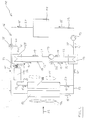
- FIG. 1 shows a schematic representation generally designated 10 vehicle cooling circuit for cooling a temperature-increasing Device 11 by means of a coolant.
- the vehicle cooling circuit 10 has a coolant circuit 16 and a heat pump circuit 18.
- the coolant is conveyed in the coolant circuit 16 according to arrows 15, while a refrigerant according to arrows 17 is passed through the heat pump circuit 18.
- the coolant circuit 16 is the temperature increasing Integrated device 11, which by means of a Coolant line 26 with the cooler 12 for conveying coolant is connected according to arrow 15.
- a coolant line 27 leads from the cooler 12 to Heat exchanger 14, which on its coolant side Exit by means of a coolant line 28 is connected to a coolant pump 13.
- Of the Coolant pump 13 leads a coolant line 29 to the entry side of the temperature increasing device 11. The coolant is thus according to arrows 15 from the temperature increasing device 11 through appropriate coolant lines to the radiator 12, then to the heat exchanger 14, then to Coolant pump 13 and finally back again led to the temperature increasing device 11.
- the heat pump circuit 18 has the coolant circuit 16 coupled heat exchanger 14 on the on the refrigerant outlet side by means of a refrigerant line 33 connected to a compressor 19 is.
- a refrigerant line leads from the compressor 19 30 to a capacitor 20, which is on its outlet side by means of a refrigerant line 31 an expansion valve 21 is connected.
- a refrigerant line 32 leads from the expansion valve 21 to the refrigerant inlet side of the heat exchanger 14. The refrigerant is thus in the heat pump circuit 18 according to arrows 17 from heat exchanger 14 to Compressor 19 out, then to the condenser 20 passed, from this to the expansion valve 21 and finally returned to the heat exchanger 14.
- the heat exchanger 14 contains four connections, whereby One inlet and one outlet connection for the coolant and for the refrigerant are.
- the heat exchanger 14 forms an evaporator of the heat pump circuit operated with refrigerant 18.
- a fan 24 is provided which is suitable generate a cooling air flow (arrow 22) which for cooling both the coolant in the cooler 12 and also used the refrigerant in the condenser 20 becomes.
- the fan 24 Pressure fan
- can also be designed as a suction fan Fan 25 may be provided.
- the cooler 12 and the condenser 20 are in the direction of air flow (arrow 22) seen arranged in such a way that initially the cooler 12 and then the condenser 20 is interspersed with cooling air.
- the first embodiment according to FIG. 1 is advantageous because heated coolant first by means of air cooling in the cooler 12 is precooled and then by means of the evaporator Heat exchanger 14 to a desired operating temperature is cooled. Because of this coupling of the heat pump circuit 18 with the coolant circuit 16 on the "cold" side of the coolant circuit 16 is an increase in the total cooling capacity compared to traditional systems of approx 20 to 50% possible. This is one of the reasons attributable to the fact that at the outlet of the cooler 12 existing at a relatively low temperature level Heat from the heat pump to a higher temperature level is lifted on which a heat exchanger 20 at the increased temperature difference accordingly can dissipate more heat.
- the final cooling of the coolant pre-cooled in the cooler 12 to a desired lower coolant temperature by the Heat exchanger 1 is still possible if the upper coolant temperature at the inlet of the Radiator 12 is higher than in previously known Systems. Increased by this temperature increase the heat output of the cooler 12. This results in the total cooling capacity of the vehicle cooling circuit 10 with respect to the coolant from the summation of the cooling capacity of the cooler 12 and the cooling capacity of the heat exchanger 14. Die Cooling capacity of the condenser 20 is preferably approximately 10 to 60% of the total output of the Vehicle cooling circuit 10.
- At the temperature-increasing Device 11 can be, for example a fuel cell or an internal combustion engine or another functional unit of a vehicle act. The further functioning of the vehicle cooling circuit 10 according to FIG. 1 is in itself is known and is therefore not described in detail.
- FIG. 2 shows a second, alternative embodiment a vehicle cooling circuit 10, wherein in Difference from the embodiment according to FIG. 1 only the heat pump circuit 18 changed in this way is that from the compressor 19 a refrigerant line 34 with the interposition of a 3-way valve 64 leads to a radiator 35 which by means of a Refrigerant line 36 is operatively connected to the condenser 20 is.
- a return line 65 connects the refrigerant line 36 with the 3-way valve 64.
- the heater 35 is thus on the high pressure side of the heat pump circuit 18 downstream to the compressor 19 and arranged upstream of the capacitor 20.
- the heating element 35 can advantageously used for example for vehicle interior heating be because the penetrating the radiator 35 and heated refrigerant heat on the same emits.
- the embodiment according to FIG. 2 corresponds furthermore regarding the construction and the mode of operation of that of Figure 1, so that to a detailed description of the second embodiment is waived.
- FIG. 3 shows a third, alternative embodiment a vehicle cooling circuit 10, the with respect to the embodiment according to FIG. 2 differs in particular in that a radiator 54 is integrated in the coolant circuit 16 and not, as in Figure 2, in the heat pump circuit 18.
- FIG. 3 leads a coolant line 37 from the temperature increasing device 11 to a three-way valve 38 located at one of its outlets by means of a coolant line 39 with the Radiator 12 is operatively connected and on its second Exit by means of a coolant line 40 a heat exchanger 58 which is connected in turn coupled to the heat pump circuit 18 is.
- a coolant line leads from the heat exchanger 58 42 to the radiator 54, which by means of a Coolant line 43 with the coolant line 39 and thus communicates with the cooler 12.
- the heat pump circuit 18 is designed such that from the compressor 19 a refrigerant line 44 leads to a three-way valve 45, which at one Outlet side with the heat exchanger 58 and on its second outlet side with a refrigerant line 46 is connected, which to another Three-way valve 47 leads.
- the heat exchanger 58 is on its refrigerant outlet side with the Refrigerant line 46 connected.
- From the three-way valve 47 leads a refrigerant line 48 to the condenser 20, which means on its exit side the refrigerant line 31 with the expansion valve 21 communicates.
- From the second exit side of the three-way valve 47 leads a refrigerant line 49 directly to the refrigerant line 31 forming a bypass.
- heat transfer by means of the heat exchanger 58 from the warmed refrigerant to that too heated coolant, followed by the coolant is led to the radiator 54.
- the heat exchanger 58 serves as second at the same time Condenser in relation to the refrigerant that is connected upstream of the capacitor 20.
- the radiator 54 can also be used here, for example, to heat the vehicle interior be used.
- the Three-way valve 38 it is possible to use the radiator 54 in the vehicle cooling circuit 10 if necessary switch on with variable intensity. Also allowed the three-way valve 45 a corresponding connection or activation of the heat exchanger 58.
- the three-way valve 47 allows one if necessary, intensity-variable integration circuit of the condenser 20 in the heat pump circuit 18.
- the exemplary embodiment according to FIG. 3 is characterized by a particularly flexible Operational adjustability of both the coolant circuit 16 and the heat pump circuit 18.
- the further structure and the corresponding mode of operation the embodiment of Figure 3 is in itself known, so on their detailed description is waived.
- FIG 4 shows a third, alternative embodiment a vehicle cooling circuit 10, at which also has a radiator 54 in the coolant circuit 16 is integrated.
- the heater 54 is a Upstream heat exchanger 58, which with the Heat pump circuit 18 is coupled and in relation to the refrigerant serves as a condenser.
- the heat pump circuit 18 is designed such that from the compressor 19 a refrigerant line 51 to Heat exchanger 58 leads, which on its refrigerant outlet side by means of a refrigerant line 52 operatively connected to the expansion valve 21 is.
- the refrigerant line leads from the expansion valve 21 32 to the heat exchanger 14, which with respect to the refrigerant acts as an evaporator.
- the heat exchanger 14 is on its exit side by means of Refrigerant line 33 connected to the compressor 19.
- a return line 67 is also provided, which the coolant line 55 with one in the Coolant line 42 intermediate 3-way valve 66 connects.
- the heat exchanger 58 (condenser) is in both Embodiments according to Figures 3 and 4 with provide a total of four connections, i.e. with one inlet and one outlet connection for the coolant and for the refrigerant.
- the heat pump circuit 18 does not have an air-cooled condenser, in contrast to the exemplary embodiment according to FIG. 3, an additional air-cooled condenser 20 in the heat pump circuit 18 provides.
- the coolant circuit 16 of the embodiment according to FIG. 4 differs themselves in relation to the embodiment of Figure 3 in that the radiator 54 Coolant line 55 to an auxiliary cooler 56 of the Coolant circuit 16 leads.
- the secondary cooler 56 is by means of a coolant line 57 with the coolant line 53 and thus with the heat exchanger 14 connected.
- the flowing through the secondary cooler 56 Coolant is removed by means of the cooling air flow (arrow 22) pre-cooled.
- the secondary cooler 56 is related on the cooler 12 in this way on the air side switched that the cooling air flow according to arrow 22 first the coolant in the cooler 12 and then pre-cools the coolant in the secondary cooler 56. Possibly are parallel arrangements of the Radiator 12 and the secondary cooler 56 and a corresponding Airflow possible.
- a vehicle cooling circuit according to the above described embodiments is special advantageous because - as already mentioned - an increase of the total cooling performance without impairment the cooler 12 by about 20 to 50% possible is.
- the performance of the cooler 12 even slightly increased because of the coolant temperature level is raised by approximately 1 to 2 K.
- isobutane or n-butane as Refrigerant is a pressure ratio of only approximately 2 possible, so that a COP value of 4 is reached can be.
- By means of in relation to the Air flow (arrow 22) arranged behind the cooler 12 Capacitor 20, or by means of the secondary cooler 56, will have better cooling performance achieved by the available cooling air in comparison to a single one charged with cooling air Radiator 12. It is also possible to build an integrated or integrable radiators for Use the temperature of the passenger compartment. Corresponding an embodiment, not shown can alternatively also use an absorption / adsorption heat pump be provided.
Landscapes
- Engineering & Computer Science (AREA)
- Physics & Mathematics (AREA)
- Thermal Sciences (AREA)
- Mechanical Engineering (AREA)
- Chemical & Material Sciences (AREA)
- Combustion & Propulsion (AREA)
- General Engineering & Computer Science (AREA)
- Air-Conditioning For Vehicles (AREA)
- Cooling Or The Like Of Electrical Apparatus (AREA)
Abstract
Description
- Figur 1
- ein Funktionsschaltbild des erfindungsgemäßen Fahrzeug-Kühlkreislaufs gemäß einer ersten Ausführungsform;
- Figur 2
- ein Funktionsschaltbild eines erfindungsgemäßen Fahrzeug-Kühlkreislaufs gemäß einer zweiten, alternativen Ausführungsform;
- Figur 3
- ein Funktionsschaltbild eines erfindungsgemäßen Fahrzeug-Kühlkreislaufs gemäß einer dritten, alternativen Ausführungsform und
- Figur 4
- ein Funktionsschaltbild eines erfindungsgemäßen Fahrzeug-Kühlkreislaufs gemäß einer vierten, alternativen Ausführungsform.
Claims (14)
- Fahrzeug-Kühlkreislauf für die Kühlung einer temperaturerhöhenden Einrichtung mittels eines Kühlmittels, mit einem oder mehreren, parallel und/oder in Reihe geschalteten Kühlern, einer Kühlmittelpumpe und einem zwischen der temperaturerhöhenden Einrichtung und dem Kühler angeordneten Wärmetauscher, der mit einem Wärmepumpenkreis gekoppelt ist, dadurch gekennzeichnet, dass -in Strömungsrichtung (15) des Kühlmittels gesehen- der Wärmetauscher stromabwärts zum Kühler (12) und stromaufwärts zur temperaturerhöhenden Einrichtung (11) liegt.
- Kühlkreislauf nach einem der vorhergehenden Ansprüche, dadurch gekennzeichnet, dass der Wärmetauscher (14) einen Verdampfer des mit Kältemittel betriebenen Wärmepumpenkreises (18) bildet.
- Kühlkreislauf nach einem der vorhergehenden Ansprüche, dadurch gekennzeichnet, dass der Wärmepumpenkreis (18) einen Kompressor (19), einen Kondensator (20) und ein Expansionsventil (21) aufweist.
- Kühlkreislauf nach einem der vorhergehenden Ansprüche, dadurch gekennzeichnet, dass dem Kühler (12) ein Kühlluftstrom (22) zugeordnet ist.
- Kühlkreislauf nach einem der vorhergehenden Ansprüche, dadurch gekennzeichnet, dass der Kühlluftstrom (22) sowohl den Kühler (12) als auch den Kondensator (20) kühlt.
- Kühlkreislauf nach einem der vorhergehenden Ansprüche, dadurch gekennzeichnet, dass der Kühlluftstrom (22) erst den Kühler (12) und dann den Kondensator (20) durchsetzt.
- Kühlkreislauf nach einem der vorhergehenden Ansprüche, dadurch gekennzeichnet, dass im Wärmepumpenkreis (18) ein vom Kältemittel durchströmter Heizkörper (35;54) zur Fahrzeuginnenraum-Erwärmung angeordnet ist.
- Kühlkreislauf nach einem der vorhergehenden Ansprüche, dadurch gekennzeichnet, dass der Heizkörper (35) zwischen dem Kompressor (19) und dem Kondensator (20) liegt.
- Kühlkreislauf nach einem der vorhergehenden Ansprüche, dadurch gekennzeichnet, dass der Heizkörper (54) im Kühlmittelkreis (16) angeordnet ist.
- Kühlkreislauf nach einem der vorhergehenden Ansprüche, dadurch gekennzeichnet, dass -in Strömungsrichtung (15) des Kühlmittels betrachtet- dem Heizkörper (54) ein mit dem Wärmepumpenkreis (18) gekoppelter, einen zweiten Kondensator darstellender Wärmeübertrager (58) vorgeschaltet ist.
- Kühlkreislauf nach einem der vorhergehenden Ansprüche, dadurch gekennzeichnet, dass der Wärmeübertrager (58) hinsichtlich des Wärmepumpenkreises (18) zwischen dem Kompressor (19) und dem Expansionsventil (21) liegt.
- Kühlkreislauf nach einem der vorhergehenden Ansprüche, dadurch gekennzeichnet, dass der Wärmeübertrager (58) mit dem Kühlmittelkreis (16) gekoppelt ist, dass -in Bezug auf die Strömungsrichtung (15) des Kühlmittels- dem Wärmeübertrager (58) der Heizkörper (54) nachgeschaltet ist und dass das vom Heizkörper (54) kommende Kühlmittel einen Nebenkühler (56) des Kühlmittelkreises (16) durchströmt.
- Kühlkreislauf nach einem der vorhergehenden Ansprüche, dadurch gekennzeichnet, dass der Nebenkühler (56) vom Kühlluftstrom (22) gekühlt wird.
- Kühlkreislauf nach einem der vorhergehenden Ansprüche, dadurch gekennzeichnet, dass der Kühlluftstrom (22) erst den Kühler (12) und dann den Nebenkühler (56) durchsetzt.
Applications Claiming Priority (2)
| Application Number | Priority Date | Filing Date | Title |
|---|---|---|---|
| DE10128877 | 2001-06-15 | ||
| DE10128877A DE10128877A1 (de) | 2001-06-15 | 2001-06-15 | Fahrzeug-Kühlkreislauf für die Kühlung einer temperaturerhöhenden Einrichtung mittels eines Kühlmittels |
Publications (3)
| Publication Number | Publication Date |
|---|---|
| EP1266779A2 true EP1266779A2 (de) | 2002-12-18 |
| EP1266779A3 EP1266779A3 (de) | 2005-11-23 |
| EP1266779B1 EP1266779B1 (de) | 2008-01-09 |
Family
ID=7688275
Family Applications (1)
| Application Number | Title | Priority Date | Filing Date |
|---|---|---|---|
| EP02006436A Expired - Lifetime EP1266779B1 (de) | 2001-06-15 | 2002-03-22 | Fahrzeug-Kühlkreislauf für die Kühlung einer temperaturerhöhenden Einrichtung mittels eines Kuhlmittels |
Country Status (2)
| Country | Link |
|---|---|
| EP (1) | EP1266779B1 (de) |
| DE (2) | DE10128877A1 (de) |
Cited By (7)
| Publication number | Priority date | Publication date | Assignee | Title |
|---|---|---|---|---|
| WO2003064193A1 (de) * | 2002-01-30 | 2003-08-07 | Robert Bosch Gmbh | Klimaanlage mit heizfunktion und verfahren zum betrieb einer klimaanlagen mit heizfunktion |
| FR2866472A1 (fr) * | 2004-02-16 | 2005-08-19 | Peugeot Citroen Automobiles Sa | Dispositif de regulation thermique d'une pile a combustible et module de face avant pour vehicule automobile |
| WO2012021104A1 (en) * | 2010-08-12 | 2012-02-16 | Scania Cv Ab | Arrangement for maintaining a desired operating temperature of a battery in a vehicle |
| CN102852619A (zh) * | 2011-05-06 | 2013-01-02 | 曼卡车和巴士股份公司 | 电气驱动部件的主动冷却 |
| DE102013012945A1 (de) | 2013-08-02 | 2015-02-05 | Audi Ag | Kühlungssystem |
| EP2903076B1 (de) | 2014-01-27 | 2018-12-19 | Liebherr-Transportation Systems GmbH & Co. KG | Fahrzeugkühlkreislauf |
| US10611210B2 (en) * | 2014-09-09 | 2020-04-07 | Bayerische Motoren Werke Aktiengesellschaft | Heat pump system for climate control of a vehicle, and method for operating a heat pump system of this type |
Families Citing this family (8)
| Publication number | Priority date | Publication date | Assignee | Title |
|---|---|---|---|---|
| DE10351756A1 (de) | 2003-11-06 | 2005-06-23 | Daimlerchrysler Ag | Brennstoffzellensystem für den mobilen Einsatz mit einem Adsorptionsspeicher |
| DE102004002445A1 (de) * | 2004-01-16 | 2005-08-11 | Webasto Ag | Klimagerät zur Standklimatisierung eines Fahrzeugs |
| DE102009045719A1 (de) * | 2009-10-15 | 2011-04-21 | Robert Bosch Gmbh | Kühlmittelvorrichtung |
| DE102010038406A1 (de) * | 2010-07-26 | 2012-01-26 | Behr Gmbh & Co. Kg | System für ein Kraftfahrzeug zum Erwärmen und/oder Kühlen eines Kraftfahrzeuginnenraumes und zum Kühlen eines Verbrennungsmotors |
| DE102013208115A1 (de) | 2013-05-03 | 2014-11-06 | Behr Gmbh & Co. Kg | Kühlkreislauf |
| DE102013215608A1 (de) | 2013-08-07 | 2015-02-12 | Behr Gmbh & Co. Kg | Kühlsystem und zugehöriges Betriebsverfahren |
| DE102015218824B4 (de) | 2015-09-30 | 2024-09-12 | Bayerische Motoren Werke Aktiengesellschaft | Wärmepumpensystem und Verfahren zum Betrieb eines solchen |
| DE102021201795A1 (de) | 2021-02-25 | 2022-08-25 | Siemens Mobility GmbH | Kühleinrichtung für eine Fahrzeugbatterie |
Citations (1)
| Publication number | Priority date | Publication date | Assignee | Title |
|---|---|---|---|---|
| DE19850829C1 (de) | 1998-11-04 | 2000-03-16 | Valeo Klimasysteme Gmbh | Kühl-Heiz-Kreis für ein Fahrzeug |
Family Cites Families (4)
| Publication number | Priority date | Publication date | Assignee | Title |
|---|---|---|---|---|
| DE4327261C1 (de) * | 1993-08-13 | 1994-10-13 | Daimler Benz Ag | Kühlmittelkreislauf |
| DE4433836C1 (de) * | 1994-09-22 | 1995-11-09 | Daimler Benz Ag | Vorrichtung zur Beheizung eines Innenraumes eines Elektrofahrzeuges |
| DE19818649A1 (de) * | 1998-04-25 | 1999-10-28 | Behr Gmbh & Co | Fahrzeugklimaanlage und deren Verwendung |
| DE10128164A1 (de) * | 2001-06-09 | 2002-12-12 | Behr Gmbh & Co | Fahrzeug-Kühlsystem für eine temperaturerhöhende Einrichtung sowie Verfahren zur Kühlung der temperaturerhöhenden Einrichtung |
-
2001
- 2001-06-15 DE DE10128877A patent/DE10128877A1/de not_active Withdrawn
-
2002
- 2002-03-22 DE DE50211498T patent/DE50211498D1/de not_active Expired - Lifetime
- 2002-03-22 EP EP02006436A patent/EP1266779B1/de not_active Expired - Lifetime
Patent Citations (1)
| Publication number | Priority date | Publication date | Assignee | Title |
|---|---|---|---|---|
| DE19850829C1 (de) | 1998-11-04 | 2000-03-16 | Valeo Klimasysteme Gmbh | Kühl-Heiz-Kreis für ein Fahrzeug |
Cited By (17)
| Publication number | Priority date | Publication date | Assignee | Title |
|---|---|---|---|---|
| WO2003064193A1 (de) * | 2002-01-30 | 2003-08-07 | Robert Bosch Gmbh | Klimaanlage mit heizfunktion und verfahren zum betrieb einer klimaanlagen mit heizfunktion |
| FR2866472A1 (fr) * | 2004-02-16 | 2005-08-19 | Peugeot Citroen Automobiles Sa | Dispositif de regulation thermique d'une pile a combustible et module de face avant pour vehicule automobile |
| CN103068602B (zh) * | 2010-08-12 | 2015-06-24 | 斯堪尼亚商用车有限公司 | 用于维持车辆中的电池的期望工作温度的装置 |
| EP2603389A4 (de) * | 2010-08-12 | 2018-03-28 | Scania CV AB | Anordnung zur aufrechterhaltung einer gewünschten betriebstemperatur einer batterie in einem fahrzeug |
| CN103068602A (zh) * | 2010-08-12 | 2013-04-24 | 斯堪尼亚商用车有限公司 | 用于维持车辆中的电池的期望工作温度的装置 |
| US20130118707A1 (en) * | 2010-08-12 | 2013-05-16 | Zoltan Kardos | Arrangement for maintaining a desired operating temperature of a battery in a vehicle |
| RU2529068C1 (ru) * | 2010-08-12 | 2014-09-27 | Сканиа Св Аб | Устройство для поддержания необходимой температуры батареи в транспортном средстве |
| US9758009B2 (en) | 2010-08-12 | 2017-09-12 | Scania Cv Ab | Arrangement for maintaining a desired operating temperature of a battery in a vehicle |
| WO2012021104A1 (en) * | 2010-08-12 | 2012-02-16 | Scania Cv Ab | Arrangement for maintaining a desired operating temperature of a battery in a vehicle |
| EP2520452A3 (de) * | 2011-05-06 | 2016-06-15 | MAN Truck & Bus AG | Aktive Kühlung elektrischer Antriebskomponenten |
| CN102852619B (zh) * | 2011-05-06 | 2017-03-01 | 曼卡车和巴士股份公司 | 电气驱动部件的主动冷却 |
| CN102852619A (zh) * | 2011-05-06 | 2013-01-02 | 曼卡车和巴士股份公司 | 电气驱动部件的主动冷却 |
| DE102013012945A1 (de) | 2013-08-02 | 2015-02-05 | Audi Ag | Kühlungssystem |
| DE102013012945B4 (de) | 2013-08-02 | 2019-03-28 | Audi Ag | Verfahren zur Kühlung eines Nebenverbrauchers unter Verwendung eines Kühlungssystems zur Abfuhr von Wärme |
| EP2903076B1 (de) | 2014-01-27 | 2018-12-19 | Liebherr-Transportation Systems GmbH & Co. KG | Fahrzeugkühlkreislauf |
| EP2903076B2 (de) † | 2014-01-27 | 2022-08-10 | Liebherr-Transportation Systems GmbH & Co. KG | Fahrzeugkühlkreislauf |
| US10611210B2 (en) * | 2014-09-09 | 2020-04-07 | Bayerische Motoren Werke Aktiengesellschaft | Heat pump system for climate control of a vehicle, and method for operating a heat pump system of this type |
Also Published As
| Publication number | Publication date |
|---|---|
| DE50211498D1 (de) | 2008-02-21 |
| EP1266779A3 (de) | 2005-11-23 |
| EP1266779B1 (de) | 2008-01-09 |
| DE10128877A1 (de) | 2002-12-19 |
Similar Documents
| Publication | Publication Date | Title |
|---|---|---|
| EP3454401B1 (de) | Kraftfahrzeug mit einem kühlsystem | |
| EP2608973B1 (de) | Heiz-/kühleinrichtung und heiz-/kühl-modul für eine heiz-/kühleinrichtung | |
| DE60112279T2 (de) | Fahrzeug- temperaturregulierungssystem mit wärmepumpe | |
| DE10036038B4 (de) | Verfahren zum Betrieb einer Klimaanlage eines Kraftfahrzeuges | |
| DE60102185T2 (de) | Kraftfahrzeugklimaanlage | |
| EP1266779B1 (de) | Fahrzeug-Kühlkreislauf für die Kühlung einer temperaturerhöhenden Einrichtung mittels eines Kuhlmittels | |
| DE102016006682A1 (de) | Verfahren zum Betreiben einer Klimaanlage eines Elektro- oder Hybridfahrzeugs sowie Klimaanlage zur Durchführung des Verfahrens | |
| EP1164035A2 (de) | Klimaanlage mit Klimatisierungs-und Wärmepumpenmodus | |
| EP1319536A1 (de) | Klimatisierungseinrichtung für ein Fahrzeug | |
| EP4171977B1 (de) | Thermomanagementsystem für ein elektrofahrzeug und verfahren zu dessen betrieb | |
| DE19644583A1 (de) | Fahrzeugklimaanlage mit mehreren Kondensatoren und/oder Verdampfern | |
| DE102017118425A1 (de) | Kreislaufsystem für ein Fahrzeug und Verfahren dazu | |
| DE102021127770A1 (de) | Thermomanagementsystem für ein Kraftfahrzeug und Kraftfahrzeug mit einem solchen | |
| DE102017202472A1 (de) | Klimatisierungseinrichtung für ein Kraftfahrzeug | |
| DE102019132689A1 (de) | Wärmemanagementsystem für ein Kraftfahrzeug und Kraftfahrzeug mit einem solchen | |
| DE102016203045A1 (de) | Temperiereinrichtung zum Temperieren eines Innenraums eines Fahrzeugs sowie Verfahren zum Betreiben einer solchen Temperiereinrichtung | |
| WO2023061685A1 (de) | Thermomanagementsystem für ein kraftfahrzeug | |
| WO2023280507A1 (de) | Kältekreislauf sowie wärmemanagementsystem und kraftfahrzeug mit einem solchen | |
| DE102019130803B4 (de) | Verfahren zum Wärmemanagement eines Kraftfahrzeugs | |
| DE102016201835A1 (de) | Klimatisierungsvorrichtung für ein Kraftfahrzeug | |
| EP1462281A2 (de) | Klimaanlage mit mehreren Verdampfern für ein Kraftfahrzeug | |
| DE102013106831A1 (de) | Fahrzeugklimaanlage eines Hybrid- oder Elektrofahrzeugs | |
| DE102019132816A1 (de) | Wärmemanagementsystem für ein Kraftfahrzeug und Kraftfahrzeug mit einem solchen | |
| DE102019120229A1 (de) | Wärmemanagementsystem für ein Kraftfahrzeug, Verfahren zum Wärmemanagement eines Kraftfahrzeugs und Kraftfahrzeug mit einem Wärmemanagementsystem | |
| DE10012197B4 (de) | Thermomanagement für ein Kraftfahrzeug mit einem Kühlmittelkreislauf und einer Klimaanlage |
Legal Events
| Date | Code | Title | Description |
|---|---|---|---|
| PUAI | Public reference made under article 153(3) epc to a published international application that has entered the european phase |
Free format text: ORIGINAL CODE: 0009012 |
|
| AK | Designated contracting states |
Kind code of ref document: A2 Designated state(s): AT BE CH CY DE DK ES FI FR GB GR IE IT LI LU MC NL PT SE TR |
|
| AX | Request for extension of the european patent |
Free format text: AL;LT;LV;MK;RO;SI |
|
| RAP1 | Party data changed (applicant data changed or rights of an application transferred) |
Owner name: BEHR GMBH & CO. KG |
|
| PUAL | Search report despatched |
Free format text: ORIGINAL CODE: 0009013 |
|
| AK | Designated contracting states |
Kind code of ref document: A3 Designated state(s): AT BE CH CY DE DK ES FI FR GB GR IE IT LI LU MC NL PT SE TR |
|
| AX | Request for extension of the european patent |
Extension state: AL LT LV MK RO SI |
|
| 17P | Request for examination filed |
Effective date: 20060523 |
|
| AKX | Designation fees paid |
Designated state(s): DE FR GB IT |
|
| 17Q | First examination report despatched |
Effective date: 20060908 |
|
| GRAP | Despatch of communication of intention to grant a patent |
Free format text: ORIGINAL CODE: EPIDOSNIGR1 |
|
| GRAS | Grant fee paid |
Free format text: ORIGINAL CODE: EPIDOSNIGR3 |
|
| GRAA | (expected) grant |
Free format text: ORIGINAL CODE: 0009210 |
|
| AK | Designated contracting states |
Kind code of ref document: B1 Designated state(s): DE FR GB IT |
|
| REG | Reference to a national code |
Ref country code: GB Ref legal event code: FG4D Free format text: NOT ENGLISH |
|
| REF | Corresponds to: |
Ref document number: 50211498 Country of ref document: DE Date of ref document: 20080221 Kind code of ref document: P |
|
| GBV | Gb: ep patent (uk) treated as always having been void in accordance with gb section 77(7)/1977 [no translation filed] | ||
| ET | Fr: translation filed | ||
| PLBE | No opposition filed within time limit |
Free format text: ORIGINAL CODE: 0009261 |
|
| STAA | Information on the status of an ep patent application or granted ep patent |
Free format text: STATUS: NO OPPOSITION FILED WITHIN TIME LIMIT |
|
| PGFP | Annual fee paid to national office [announced via postgrant information from national office to epo] |
Ref country code: FR Payment date: 20080319 Year of fee payment: 7 |
|
| 26N | No opposition filed |
Effective date: 20081010 |
|
| PG25 | Lapsed in a contracting state [announced via postgrant information from national office to epo] |
Ref country code: GB Free format text: LAPSE BECAUSE OF FAILURE TO SUBMIT A TRANSLATION OF THE DESCRIPTION OR TO PAY THE FEE WITHIN THE PRESCRIBED TIME-LIMIT Effective date: 20080109 |
|
| PG25 | Lapsed in a contracting state [announced via postgrant information from national office to epo] |
Ref country code: IT Free format text: LAPSE BECAUSE OF FAILURE TO SUBMIT A TRANSLATION OF THE DESCRIPTION OR TO PAY THE FEE WITHIN THE PRESCRIBED TIME-LIMIT Effective date: 20080109 |
|
| REG | Reference to a national code |
Ref country code: FR Ref legal event code: ST Effective date: 20091130 |
|
| PG25 | Lapsed in a contracting state [announced via postgrant information from national office to epo] |
Ref country code: FR Free format text: LAPSE BECAUSE OF NON-PAYMENT OF DUE FEES Effective date: 20091123 |
|
| REG | Reference to a national code |
Ref country code: DE Ref legal event code: R082 Ref document number: 50211498 Country of ref document: DE Representative=s name: GRAUEL, ANDREAS, DIPL.-PHYS. DR. RER. NAT., DE |
|
| REG | Reference to a national code |
Ref country code: DE Ref legal event code: R081 Ref document number: 50211498 Country of ref document: DE Owner name: MAHLE INTERNATIONAL GMBH, DE Free format text: FORMER OWNER: BEHR GMBH & CO. KG, 70469 STUTTGART, DE Effective date: 20150319 Ref country code: DE Ref legal event code: R082 Ref document number: 50211498 Country of ref document: DE Representative=s name: GRAUEL, ANDREAS, DIPL.-PHYS. DR. RER. NAT., DE Effective date: 20150319 |
|
| PGFP | Annual fee paid to national office [announced via postgrant information from national office to epo] |
Ref country code: DE Payment date: 20190404 Year of fee payment: 18 |
|
| REG | Reference to a national code |
Ref country code: DE Ref legal event code: R119 Ref document number: 50211498 Country of ref document: DE |
|
| PG25 | Lapsed in a contracting state [announced via postgrant information from national office to epo] |
Ref country code: DE Free format text: LAPSE BECAUSE OF NON-PAYMENT OF DUE FEES Effective date: 20201001 |