EP3454401B1 - Kraftfahrzeug mit einem kühlsystem - Google Patents
Kraftfahrzeug mit einem kühlsystem Download PDFInfo
- Publication number
- EP3454401B1 EP3454401B1 EP18191416.9A EP18191416A EP3454401B1 EP 3454401 B1 EP3454401 B1 EP 3454401B1 EP 18191416 A EP18191416 A EP 18191416A EP 3454401 B1 EP3454401 B1 EP 3454401B1
- Authority
- EP
- European Patent Office
- Prior art keywords
- coolant
- circuit
- heat exchanger
- motor vehicle
- traction battery
- Prior art date
- Legal status (The legal status is an assumption and is not a legal conclusion. Google has not performed a legal analysis and makes no representation as to the accuracy of the status listed.)
- Active
Links
Images



Classifications
-
- B—PERFORMING OPERATIONS; TRANSPORTING
- B60—VEHICLES IN GENERAL
- B60H—ARRANGEMENTS OF HEATING, COOLING, VENTILATING OR OTHER AIR-TREATING DEVICES SPECIALLY ADAPTED FOR PASSENGER OR GOODS SPACES OF VEHICLES
- B60H1/00—Heating, cooling or ventilating devices
- B60H1/00271—HVAC devices specially adapted for particular vehicle parts or components and being connected to the vehicle HVAC unit
-
- B—PERFORMING OPERATIONS; TRANSPORTING
- B60—VEHICLES IN GENERAL
- B60K—ARRANGEMENT OR MOUNTING OF PROPULSION UNITS OR OF TRANSMISSIONS IN VEHICLES; ARRANGEMENT OR MOUNTING OF PLURAL DIVERSE PRIME-MOVERS IN VEHICLES; AUXILIARY DRIVES FOR VEHICLES; INSTRUMENTATION OR DASHBOARDS FOR VEHICLES; ARRANGEMENTS IN CONNECTION WITH COOLING, AIR INTAKE, GAS EXHAUST OR FUEL SUPPLY OF PROPULSION UNITS IN VEHICLES
- B60K11/00—Arrangement in connection with cooling of propulsion units
- B60K11/02—Arrangement in connection with cooling of propulsion units with liquid cooling
-
- B—PERFORMING OPERATIONS; TRANSPORTING
- B60—VEHICLES IN GENERAL
- B60H—ARRANGEMENTS OF HEATING, COOLING, VENTILATING OR OTHER AIR-TREATING DEVICES SPECIALLY ADAPTED FOR PASSENGER OR GOODS SPACES OF VEHICLES
- B60H1/00—Heating, cooling or ventilating devices
- B60H1/00271—HVAC devices specially adapted for particular vehicle parts or components and being connected to the vehicle HVAC unit
- B60H1/00278—HVAC devices specially adapted for particular vehicle parts or components and being connected to the vehicle HVAC unit for the battery
-
- B—PERFORMING OPERATIONS; TRANSPORTING
- B60—VEHICLES IN GENERAL
- B60H—ARRANGEMENTS OF HEATING, COOLING, VENTILATING OR OTHER AIR-TREATING DEVICES SPECIALLY ADAPTED FOR PASSENGER OR GOODS SPACES OF VEHICLES
- B60H1/00—Heating, cooling or ventilating devices
- B60H1/00357—Air-conditioning arrangements specially adapted for particular vehicles
- B60H1/00385—Air-conditioning arrangements specially adapted for particular vehicles for vehicles having an electrical drive, e.g. hybrid or fuel cell
-
- B—PERFORMING OPERATIONS; TRANSPORTING
- B60—VEHICLES IN GENERAL
- B60H—ARRANGEMENTS OF HEATING, COOLING, VENTILATING OR OTHER AIR-TREATING DEVICES SPECIALLY ADAPTED FOR PASSENGER OR GOODS SPACES OF VEHICLES
- B60H1/00—Heating, cooling or ventilating devices
- B60H1/00357—Air-conditioning arrangements specially adapted for particular vehicles
- B60H1/00385—Air-conditioning arrangements specially adapted for particular vehicles for vehicles having an electrical drive, e.g. hybrid or fuel cell
- B60H1/00392—Air-conditioning arrangements specially adapted for particular vehicles for vehicles having an electrical drive, e.g. hybrid or fuel cell for electric vehicles having only electric drive means
-
- B—PERFORMING OPERATIONS; TRANSPORTING
- B60—VEHICLES IN GENERAL
- B60H—ARRANGEMENTS OF HEATING, COOLING, VENTILATING OR OTHER AIR-TREATING DEVICES SPECIALLY ADAPTED FOR PASSENGER OR GOODS SPACES OF VEHICLES
- B60H1/00—Heating, cooling or ventilating devices
- B60H1/32—Cooling devices
- B60H1/3204—Cooling devices using compression
-
- B—PERFORMING OPERATIONS; TRANSPORTING
- B60—VEHICLES IN GENERAL
- B60H—ARRANGEMENTS OF HEATING, COOLING, VENTILATING OR OTHER AIR-TREATING DEVICES SPECIALLY ADAPTED FOR PASSENGER OR GOODS SPACES OF VEHICLES
- B60H1/00—Heating, cooling or ventilating devices
- B60H1/32—Cooling devices
- B60H1/3204—Cooling devices using compression
- B60H1/3228—Cooling devices using compression characterised by refrigerant circuit configurations
- B60H1/32281—Cooling devices using compression characterised by refrigerant circuit configurations comprising a single secondary circuit, e.g. at evaporator or condenser side
-
- B—PERFORMING OPERATIONS; TRANSPORTING
- B60—VEHICLES IN GENERAL
- B60L—PROPULSION OF ELECTRICALLY-PROPELLED VEHICLES; SUPPLYING ELECTRIC POWER FOR AUXILIARY EQUIPMENT OF ELECTRICALLY-PROPELLED VEHICLES; ELECTRODYNAMIC BRAKE SYSTEMS FOR VEHICLES IN GENERAL; MAGNETIC SUSPENSION OR LEVITATION FOR VEHICLES; MONITORING OPERATING VARIABLES OF ELECTRICALLY-PROPELLED VEHICLES; ELECTRIC SAFETY DEVICES FOR ELECTRICALLY-PROPELLED VEHICLES
- B60L58/00—Methods or circuit arrangements for monitoring or controlling batteries or fuel cells, specially adapted for electric vehicles
- B60L58/10—Methods or circuit arrangements for monitoring or controlling batteries or fuel cells, specially adapted for electric vehicles for monitoring or controlling batteries
- B60L58/24—Methods or circuit arrangements for monitoring or controlling batteries or fuel cells, specially adapted for electric vehicles for monitoring or controlling batteries for controlling the temperature of batteries
- B60L58/26—Methods or circuit arrangements for monitoring or controlling batteries or fuel cells, specially adapted for electric vehicles for monitoring or controlling batteries for controlling the temperature of batteries by cooling
-
- H—ELECTRICITY
- H01—ELECTRIC ELEMENTS
- H01M—PROCESSES OR MEANS, e.g. BATTERIES, FOR THE DIRECT CONVERSION OF CHEMICAL ENERGY INTO ELECTRICAL ENERGY
- H01M10/00—Secondary cells; Manufacture thereof
- H01M10/60—Heating or cooling; Temperature control
- H01M10/61—Types of temperature control
- H01M10/613—Cooling or keeping cold
-
- H—ELECTRICITY
- H01—ELECTRIC ELEMENTS
- H01M—PROCESSES OR MEANS, e.g. BATTERIES, FOR THE DIRECT CONVERSION OF CHEMICAL ENERGY INTO ELECTRICAL ENERGY
- H01M10/00—Secondary cells; Manufacture thereof
- H01M10/60—Heating or cooling; Temperature control
- H01M10/62—Heating or cooling; Temperature control specially adapted for specific applications
- H01M10/625—Vehicles
-
- H—ELECTRICITY
- H01—ELECTRIC ELEMENTS
- H01M—PROCESSES OR MEANS, e.g. BATTERIES, FOR THE DIRECT CONVERSION OF CHEMICAL ENERGY INTO ELECTRICAL ENERGY
- H01M10/00—Secondary cells; Manufacture thereof
- H01M10/60—Heating or cooling; Temperature control
- H01M10/65—Means for temperature control structurally associated with the cells
- H01M10/656—Means for temperature control structurally associated with the cells characterised by the type of heat-exchange fluid
- H01M10/6567—Liquids
- H01M10/6568—Liquids characterised by flow circuits, e.g. loops, located externally to the cells or cell casings
-
- H—ELECTRICITY
- H01—ELECTRIC ELEMENTS
- H01M—PROCESSES OR MEANS, e.g. BATTERIES, FOR THE DIRECT CONVERSION OF CHEMICAL ENERGY INTO ELECTRICAL ENERGY
- H01M10/00—Secondary cells; Manufacture thereof
- H01M10/60—Heating or cooling; Temperature control
- H01M10/66—Heat-exchange relationships between the cells and other systems, e.g. central heating systems or fuel cells
- H01M10/663—Heat-exchange relationships between the cells and other systems, e.g. central heating systems or fuel cells the system being an air-conditioner or an engine
-
- B—PERFORMING OPERATIONS; TRANSPORTING
- B60—VEHICLES IN GENERAL
- B60H—ARRANGEMENTS OF HEATING, COOLING, VENTILATING OR OTHER AIR-TREATING DEVICES SPECIALLY ADAPTED FOR PASSENGER OR GOODS SPACES OF VEHICLES
- B60H1/00—Heating, cooling or ventilating devices
- B60H1/00271—HVAC devices specially adapted for particular vehicle parts or components and being connected to the vehicle HVAC unit
- B60H2001/00307—Component temperature regulation using a liquid flow
-
- H—ELECTRICITY
- H01—ELECTRIC ELEMENTS
- H01M—PROCESSES OR MEANS, e.g. BATTERIES, FOR THE DIRECT CONVERSION OF CHEMICAL ENERGY INTO ELECTRICAL ENERGY
- H01M2220/00—Batteries for particular applications
- H01M2220/20—Batteries in motive systems, e.g. vehicle, ship, plane
-
- Y—GENERAL TAGGING OF NEW TECHNOLOGICAL DEVELOPMENTS; GENERAL TAGGING OF CROSS-SECTIONAL TECHNOLOGIES SPANNING OVER SEVERAL SECTIONS OF THE IPC; TECHNICAL SUBJECTS COVERED BY FORMER USPC CROSS-REFERENCE ART COLLECTIONS [XRACs] AND DIGESTS
- Y02—TECHNOLOGIES OR APPLICATIONS FOR MITIGATION OR ADAPTATION AGAINST CLIMATE CHANGE
- Y02E—REDUCTION OF GREENHOUSE GAS [GHG] EMISSIONS, RELATED TO ENERGY GENERATION, TRANSMISSION OR DISTRIBUTION
- Y02E60/00—Enabling technologies; Technologies with a potential or indirect contribution to GHG emissions mitigation
- Y02E60/10—Energy storage using batteries
Definitions
- the invention relates to an electric motor vehicle, i.e. a motor vehicle having an electric traction motor, with a cooling system.
- the cooling system of an electric motor vehicle differs considerably from a cooling system of a motor vehicle driven exclusively by an internal combustion engine. This applies not only because in such an electric motor vehicle, if necessary additionally, components of the electric traction system, in particular the electric traction motor and a traction battery provided for supplying this traction motor with electrical energy, must be cooled, but in particular also because these components of the electric Traction system often different temperature levels must be maintained by means of the cooling system. For example, it may be necessary for an intended operating temperature range for the traction battery to be significantly below the intended operating temperature range for the electric traction motor, which may require it to be cooled by separate coolant flows with different coolant temperatures.
- Cooling systems for electric vehicles are, for example, from the DE 10 2007 004 979 A1 , the DE 10 2012 024 080 A1 , the DE 10 2015 101 186 A1 , the DE 10 2015 208 862 A1 , the DE 10 2015 220 623 A1 , the DE 10 2012 108 043 A1 and the US 2016/107505 A1 known.
- the cooling systems disclosed therein are functionally restricted or designed to be relatively complex.
- the invention was based on the object of specifying a cooling system for an electric motor vehicle which has a structure that is as simple as possible.
- an electric motor vehicle which has a cooling system that has at least one electric traction motor (or one or more cooling channels thereof), an ambient heat exchanger, a bypass to the ambient heat exchanger, a traction battery (or one or more cooling channels thereof), preferably an electrical one Coolant heating device, a coolant-refrigerant heat exchanger of an air conditioner, a first coolant pump and a second coolant pump, which are directly or indirectly connected to one another in a fluid-conducting manner via coolant lines and a distribution system.
- a cooling system that has at least one electric traction motor (or one or more cooling channels thereof), an ambient heat exchanger, a bypass to the ambient heat exchanger, a traction battery (or one or more cooling channels thereof), preferably an electrical one Coolant heating device, a coolant-refrigerant heat exchanger of an air conditioner, a first coolant pump and a second coolant pump, which are directly or indirectly connected to one another in a fluid-conducting manner via coolant lines and a distribution system.
- Ambient heat exchanger is understood to mean a heat exchanger in which the coolant of the cooling system can be cooled by a transfer of thermal energy to ambient air that flows through and / or around the heat exchanger.
- air conditioner is understood to mean a device by means of which air that is to be supplied to an interior of the motor vehicle can be tempered, which can require both heating and cooling of the air.
- the air conditioning unit can preferably be designed in the form of a cycle device for performing a thermodynamic cycle and for this purpose at least one compressor for compressing the then gaseous refrigerant, a condenser for liquefying the previously gaseous refrigerant with the release of thermal energy, a throttle for in a refrigerant-receiving circuit system Reduction of the pressure of the then liquid refrigerant and an evaporator for evaporating the previously liquid refrigerant while absorbing thermal energy are integrated.
- such a cycle device of the air conditioner can also include a pump for conveying the refrigerant within the cycle system.
- the air-conditioning device also includes a preferably electrical auxiliary heater, the thermal energy of which can be transferred directly or indirectly, i.e. via the refrigerant, to the air to be supplied to the interior of the motor vehicle.
- the coolant-refrigerant heat exchanger integrated into the cooling system is the evaporator of the cycle device.
- the fluid-conducting connection between the named components of a motor vehicle according to the invention is provided in such a way that, in a first functional position of the distribution system, August 5, 2019 on the one hand (in particular liquid) coolant can be conveyed by means of the first coolant pump in a first coolant circuit comprising the traction motor, the bypass to the ambient heat exchanger and the coolant-refrigerant heat exchanger.
- thermal energy that is transferred in the coolant-refrigerant heat exchanger from the coolant flowing through the first coolant cooling circuit to a refrigerant of the air conditioning unit can be used to heat an interior of the motor vehicle.
- either an auxiliary heater of the air conditioning unit can become superfluous or the heating power to be applied by it to heat the air to be supplied to the interior of the motor vehicle can be kept low, which on the one hand enables the auxiliary heater to be relatively small and therefore easy and inexpensive to dimension, as well as to convert it into thermal energy to keep the energy to be supplied low.
- this can have a particularly advantageous effect on the electrical range of the motor vehicle.
- the air-conditioning device that at least includes a cycle device, it can be provided that it is operated as a heat pump in the first functional position of the distribution system, so that the waste heat of the first coolant circuit, together with, in particular, from the compressor, into the refrigerant energy introduced (overpressure) is transferred as useful heat in the condenser to the air provided for temperature control of the interior of the motor vehicle. Since the thermal energy (waste heat) absorbed by the coolant when it flows through the first coolant circuit is to be used as exclusively as possible for heating the interior of the motor vehicle, it is provided that the first coolant circuit integrates the bypass to the ambient heat exchanger, so that the coolant is at least partially and preferably is completely routed through this bypass. The ambient heat exchanger itself can therefore preferably not be integrated into the first coolant circuit and therefore also cannot be flowed through by the coolant.
- coolant can be conveyed by means of the second coolant pump in a second coolant circuit (preferably exclusively in addition to the second coolant pump) comprising the traction battery and the coolant heating device, which is separate from the first coolant circuit.
- a second coolant circuit preferably exclusively in addition to the second coolant pump
- the coolant heating device which is separate from the first coolant circuit.
- An operation of the motor vehicle or the cooling system based on the first functional position of the distribution system can be useful in particular directly or shortly after a cold start of the motor vehicle, ie start-up after the components of the motor vehicle have essentially completely cooled down to ambient temperature, with relatively low ambient temperatures at the same time in order to achieve the fastest possible and energetically advantageous heating of both the interior of the motor vehicle and the traction battery.
- a "separation" of different cooling circuits of the cooling system of a motor vehicle according to the invention is understood according to the invention to mean that there is no relevant exchange of coolant between them during operation of the cooling system, i.e. when coolant is conveyed by means of the coolant pumps.
- a second functional position of the distribution system in which, on the one hand, coolant can be conveyed by means of the first coolant pump in a third coolant circuit comprising the traction motor and the ambient heat exchanger, and coolant by means of the second coolant pump in a fourth comprising the traction battery and the coolant-refrigerant heat exchanger Coolant circuit, which is separate from the third coolant circuit, can be conveyed.
- thermal energy that is transferred in the coolant-refrigerant heat exchanger from the coolant flowing through the fourth coolant cooling circuit to the coolant of the air conditioning unit can be used to cool the traction battery, ie it an active cooling of the traction battery via the coolant circulating in the fourth coolant circuit by means of the air-conditioning device is then provided.
- the air-conditioning device that at least includes a cycle device, it can accordingly be provided that it is operated as a refrigeration machine in the second functional position of the distribution system.
- waste heat which is transferred from the components integrated in the third coolant circuit, in particular the traction motor, to the coolant circulating therein, is then at least partially, preferably, into the coolant circulation discharge fully integrated ambient heat exchanger from the cooling system or the motor vehicle.
- An operation of the motor vehicle or the cooling system based on the second functional position of the distribution system can in particular be provided after all components integrated in the cooling system, for which a cooling effect is to be achieved at least temporarily by means of the cooling system, each have reached a defined operating temperature range.
- the second functional position of the distribution system is only set if the temperature of the coolant upstream of the traction battery is above a defined limit temperature or a defined limit temperature range, for example between 25 ° C and 35 ° C, the specific limit temperature can vary within this range, in particular depending on the load with which the traction motor is operated.
- the active cooling of the traction battery by means of the air conditioner can then ensure a sufficient cooling effect for the traction battery.
- a particularly simple and therefore advantageous interconnection of the components of the cooling system of a motor vehicle according to the invention can be implemented if a main circuit integrating at least the traction motor, the combination of ambient heat exchanger and associated bypass, the traction battery, the first coolant pump and the second coolant pump in series is provided. Furthermore, there is then a first short-circuit line integrating the coolant heating device, which bridges a section of the main circuit that integrates the traction battery and the second coolant pump, as well as a second short-circuit line integrating the coolant-refrigerant heat exchanger, one the traction battery, the second coolant pump and the branches to the first Short-circuit line integrating section of the main circuit bridged, provided.
- a distribution device of the is also required in at least one branch of the main circuit to the first short-circuit line and / or to the second short-circuit line Integrated distribution system.
- the distribution device can preferably be designed in the form of a valve that can be actively controlled by means of a control device of the motor vehicle, in particular in the form of a switching valve and / or a 3/2-way valve.
- coolant is by means of the first coolant pump in a (possibly exclusively) the traction motor and the bypass to the ambient heat exchanger comprising fifth coolant circuit can be conveyed. Furthermore, it should then be possible to convey coolant by means of the second coolant pump in the second coolant circuit, which is separate from the fifth coolant circuit. Accordingly, it can be provided that an operation of the cooling system based on the third functional position of the distribution system differs from that based on the first functional position in that no waste heat from the cooling system should be used to heat the interior of the motor vehicle.
- a cooling system can advantageously comprise a third short-circuit line that bridges a section of the main circuit that (preferably exclusively) bridges the traction battery, the second coolant pump, the branches to the first short-circuit line and the branches to the second short-circuit line.
- a distribution device of the distribution system can furthermore preferably be integrated in at least one branch to the third short-circuit line.
- This distribution device can also preferably be designed in the form of a valve that can be actively controlled by means of a control device of the motor vehicle, in particular in the form of a switching valve and / or a 3/2-way valve.
- flow through the second short-circuit line comprising the coolant-refrigerant heat exchanger is also possible instead of the third short-circuit line that may then not be present, without thermal energy, which might be transferred to a small extent from the coolant to the refrigerant, for heating purposes the air to be supplied to the interior of the motor vehicle would be used, for example by then not operating a cycle device of the air conditioner.
- An operation of the motor vehicle or the cooling system based on the third functional position of the distribution system can be useful in particular directly or shortly after a cold start of the motor vehicle and at relatively low ambient temperatures, because the traction battery is then heated by means of the coolant heating device via the coolant conveyed separately in the second coolant circuit makes sense.
- a use of waste heat from the fifth coolant circuit for heating the air to be supplied to the interior of the motor vehicle, which is not provided according to the third functional position, can be due in particular to the fact that the coolant flowing through the fifth coolant circuit should first be heated immediately after a cold start before using this coolant a sufficient and as constant as possible heat transfer to the refrigerant in the coolant-refrigerant heat exchanger (according to an operation based on the first functional position of the distribution system) can take place. It can be provided that, after a cold start of the motor vehicle, the cooling system is initially operated based on the third functional position before a switch is made to operation based on the first functional position. However, direct operation of the cooling system based on the first functional position after a cold start of the motor vehicle is also possible.
- coolant in a fourth functional position of the distribution system, can be conveyed by means of the first coolant pump and the second coolant pump in a sixth coolant circuit comprising the traction motor, the ambient heat exchanger and the traction battery. Accordingly, it can be provided that all components to be cooled are integrated into a common, namely the sixth, coolant circuit and consequently let the same coolant flow through them. This can be particularly useful if this coolant has a temperature that is still sufficiently low for an existing cooling power requirement of the traction battery or can be kept sufficiently low due to the flow through the ambient heat exchanger.
- a switchover of an operation of the cooling system based on the fourth functional position to an operation of the Cooling system based on the second functional position can be necessary in particular if the temperature of the coolant upstream of the traction battery is above a limit value or a limit temperature range, for example between 25 ° C and 35 ° C, the specific limit temperature within this range, in particular depending on the load , with which the traction motor is operated, can vary, and therefore no sufficient cooling capacity for the traction battery can be achieved by means of the ambient heat exchanger and the coolant flowing through the sixth coolant circuit.
- coolant in a fifth functional position of the distribution system, can be conveyed by means of the first coolant pump and the second coolant pump in a seventh coolant circuit comprising the traction motor, the bypass to the ambient heat exchanger and the traction battery.
- An operation of the cooling system based on the fifth functional position of the distribution system can therefore differ from that based on the fourth functional position only in that the bypass to the ambient heat exchanger (mainly or completely) is flowed through by the coolant.
- An operation of the cooling system based on this fifth functional position can be useful, for example, if the traction battery already has a cooling capacity requirement and at the same time the traction motor has not yet reached its intended operating temperature range, so that thermal energy that flows through (the cooling channels) of the traction battery is transferred to the coolant flowing through the seventh coolant circuit passes over, can be used to warm up the traction motor and / or other components that are also integrated in this seventh coolant circuit.
- the electric motor vehicle according to the invention is also preferably an electric vehicle in which the drive power to be applied to move the motor vehicle is generated exclusively by the electric traction motor and possibly by one or more further electric traction motors.
- the electric motor vehicle can be a hybrid vehicle which, in addition to at least one / the electric traction motor, also has an internal combustion engine which is also provided at least at times to generate drive power for the motor vehicle.
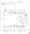
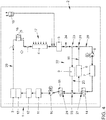
- the Figs. 1 to 5 show in greatly simplified representations a motor vehicle 1 according to the invention with a cooling system 2.
- the cooling system 2 comprises, as components to be integrated, an electric traction motor 3, an ambient heat exchanger 4, a DC-DC converter 5, a second electric coolant pump 6, a traction battery 7, a electric coolant heating device 8, a coolant-refrigerant heat exchanger 9 of an air conditioning device (otherwise not shown), a first electric coolant pump 10, a first charger 11 for charging the traction battery 7, which is based on inductive energy transfer, a second charger 12 for charging the traction battery 7 , in which an electrically conductive connection with an electrical energy source is to be established by means of a plug connection, as well as power electronics 13 assigned to traction motor 3, which can in particular include a pulse-controlled inverter.
- thermostatic valve 16 which can be designed, for example, in the form of a purely passive valve operated by means of an expansion element, includes. Furthermore, a bypass 17 to the ambient heat exchanger 4 is provided, the flow of coolant being controlled via the ambient heat exchanger 4 and / or the bypass 17 by means of the thermostatic valve 16. For example, it can be provided that the thermostatic valve 16 begins to open at a temperature of the coolant applied to it (and thus of its expansion element) of approx. 15 ° C and is fully open at a temperature of approx. 25 ° C.
- the entire volume flow of the coolant arriving at the thermostatic valve 16 is accordingly via the bypass 17 and at a temperature above approx. 25 ° C completely via the ambient heat exchanger 4 guided.
- the cooling system also has an expansion tank 18 in a known manner.
- the interconnection of the components by means of the coolant lines and the two switching valves 14, 15 is selected in such a way that the traction motor 3, the combination of ambient heat exchanger 4 and associated bypass 17, the DC-DC converter 5, the second coolant pump 6, the traction battery 3, the first coolant pump 10, the first charger 11, the second charger 12 and the power electronics 13 are integrated in series into a main circuit of the cooling system and consequently the same coolant would flow through one after the other in a coolant circuit corresponding to the main circuit. Furthermore, the interconnection is selected such that the traction motor 3, the DC-DC converter 5 and the chargers 11, 12 always when at least the first coolant pump 10 is in operation would flow through jointly (in series). For the sake of simplicity, these components of the cooling system are also referred to below as high-temperature cooling components.
- the coolant heating device 8 is integrated in a first short-circuit line 19 which bridges a section of the main circuit comprising the traction battery 7 and the second coolant pump 6.
- the coolant-refrigerant heat exchanger 9 is integrated in a second short-circuit line 20, which bridges a section of the main circuit that integrates the traction battery 7, the second coolant pump 6 and the branches 21 to the first short-circuit line 19.
- a third short-circuit line 22 is provided, which bridges a section of the main circuit integrating the traction battery 7, the second coolant pump 6, the branches 21 to the first short-circuit line 19 and the branches 23 to the second short-circuit line 20.
- a first (14) of the switching valves 14, 15 of the distribution system is integrated into the branch 21 of the main circuit to the first short-circuit line 19, which is located downstream with respect to the conveying direction provided for the second coolant pump 6.
- coolant coming from the traction battery 7 is either guided further along the main circuit or into the first short-circuit line 19.
- the second (15) of the switching valves 14, 15 of the distribution system is integrated into the branch 24 of the main circuit to the third short-circuit line 22, which is located on the suction side of the first coolant pump 10.
- coolant coming from the DC-DC converter 5 is either guided further along the main circuit or into the third short-circuit line 22.
- Figs. 1 to 5 show the same cooling system in different operating modes, which are based on different functional positions of the distribution system or the switching valves 14, 15 and the thermostatic valve 16. Those coolant lines (including the bypass 17) through which the relevant volume flows of the coolant are routed in the respective operating modes are shown with thicker lines compared to those coolant lines for which this does not apply.
- the Fig. 1 shows an operation of the cooling system based on a third functional position of the distribution system.
- coolant is conveyed by means of the first coolant pump 10 in a fifth coolant circuit comprising (exclusively) the high-temperature cooling components and the bypass 17 to the ambient heat exchanger 4.
- coolant is supplied by means of the second coolant pump 6 in the second coolant circuit 26, which is separate from the fifth coolant circuit 25 and which exclusively includes the traction battery 7 and the Coolant heating device 8 comprises, promoted.
- Such an operation of the cooling system is provided after a cold start of the motor vehicle 1 at relatively low ambient and therefore also cell temperatures (e.g.
- the cooling system can be operated based on a first functional position according to FIG Fig. 2 be switched. Alternatively, however, it is also possible to operate the cooling system based on the first functional position directly after a cold start of the motor vehicle 1 at relatively low ambient and therefore also cell temperatures.
- the operation based on the first functional position according to Fig. 2 differs from that according to the Fig. 1 only to the effect that the coolant that was previously circulated in the fifth coolant circuit 25 no longer flows through the third short-circuit line 22 as a result of switching over the second switching valve 15 but through the second short-circuit line 20 comprising the coolant-refrigerant heat exchanger 9 and thus within a first coolant circuit 27 circulates.
- the sufficiently heated coolant that flows in this first coolant circuit 27 is then used to transfer thermal energy in the coolant-refrigerant heat exchanger 9 to a refrigerant of a cycle device of the air conditioning unit, which can be operated as a heat pump to convert air, which is to be fed to an interior of the motor vehicle 1 to be heated as well as possible.
- coolant is conveyed by means of the two coolant pumps 6, 10 in a seventh coolant circuit 28 corresponding to the main circuit when the bypass is activated.
- a relatively small, but not insignificant amount of Coolant flow via the second short-circuit line 26 and the coolant-refrigerant heat exchanger 9 integrated therein.
- the air conditioning unit can be deactivated during such an operation of the cooling system, there is then no or only an insignificant transfer of thermal energy from the coolant to the refrigerant of the air conditioning unit.
- Such an operation of the cooling system can be based on an operation based on the first functional position according to FIG Fig.
- An operation of the cooling system based on the fifth functional position of the distribution system according to FIG Fig. 3 an operation based on a fourth functional position according to FIG Fig. 4 connect.
- All of the components to be cooled, which are integrated into the cooling system, are then cooled by means of the same coolant, which is guided serially through these components when flowing through a corresponding sixth coolant circuit 29, and the thermal energy transferred to the coolant is, if not partially is used by operating the air conditioner to heat the interior of the motor vehicle, released as waste heat via the ambient heat exchanger 4 to the ambient air.
- An operation of the cooling system based on the fourth functional position according to FIG Fig. 4 can, depending on the power requirement on the traction motor 3 and thus also on the traction battery 7 as well as depending on the ambient temperature, be provided permanently or as a normal operating mode after the components of the cooling system to be cooled have reached their respective intended operating temperature ranges.
- the cooling performance that can be achieved during operation based on the fourth functional position according to Fig. 4 is achievable for the traction battery 7, at a relatively high ambient temperature and / or with a relatively high cooling power requirement on the traction motor and the traction battery, at least temporarily not be sufficient to maintain the upper limit of the operating temperature range provided for the traction battery 7.
- coolant is conveyed by means of the first coolant pump 10 in a third coolant circuit 30 comprising the high-temperature cooling components and the ambient heat exchanger 4 in addition to the first coolant pump 15, and also coolant by means of the second coolant pump 14 in a traction battery 7 and the coolant-refrigerant heat exchanger 9 comprising fourth coolant circuit 31, which is separate from the third coolant circuit 30, promoted.
- the air conditioner comprising the coolant-refrigerant heat exchanger 9 is operated at the same time as a refrigeration machine and thereby generates a particularly high cooling capacity for cooling the traction battery 7.
Landscapes
- Engineering & Computer Science (AREA)
- Mechanical Engineering (AREA)
- Thermal Sciences (AREA)
- Physics & Mathematics (AREA)
- Chemical & Material Sciences (AREA)
- Chemical Kinetics & Catalysis (AREA)
- General Chemical & Material Sciences (AREA)
- Electrochemistry (AREA)
- Manufacturing & Machinery (AREA)
- Life Sciences & Earth Sciences (AREA)
- Sustainable Energy (AREA)
- Sustainable Development (AREA)
- Transportation (AREA)
- Combustion & Propulsion (AREA)
- Power Engineering (AREA)
- Electric Propulsion And Braking For Vehicles (AREA)
Description
- Die Erfindung betrifft ein elektrisches, d.h. einen elektrischen Traktionsmotor aufweisendes Kraftfahrzeug mit einem Kühlsystem.
- Das Kühlsystem eines elektrischen Kraftfahrzeugs, unabhängig davon, ob dieses in Form eines Hybridfahrzeugs oder als reines Elektrofahrzeug ausgebildet ist, unterscheidet sich in erheblichem Maße von einem Kühlsystem eines ausschließlich mittels eines Verbrennungsmotors angetriebenen Kraftfahrzeugs. Dies gilt nicht nur, weil bei einem solchen elektrischen Kraftfahrzeug, gegebenenfalls zusätzlich, Komponenten des elektrischen Traktionssystems, insbesondere der elektrische Traktionsmotor und eine zur Versorgung dieses Traktionsmotors mit elektrischer Energie vorgesehene Traktionsbatterie, gekühlt werden müssen, sondern insbesondere auch, weil für diese Komponenten des elektrischen Traktionssystems häufig unterschiedliche Temperaturniveaus mittels des Kühlsystems eingehalten werden müssen. Beispielsweise kann es erforderlich sein, dass ein vorgesehener Betriebstemperaturbereich für die Traktionsbatterie deutlich unterhalb des vorgesehenen Betriebstemperaturbereichs für den elektrischen Traktionsmotor liegt, was bedingen kann, diese durch separate Kühlmittelströmungen mit unterschiedlichen Kühlmitteltemperaturen zu kühlen.
- Kühlsysteme für elektrische Kraftfahrzeuge sind beispielsweise aus der
DE 10 2007 004 979 A1 , derDE 10 2012 024 080 A1 , derDE 10 2015 101 186 A1 , derDE 10 2015 208 862 A1 , derDE 10 2015 220 623 A1 , derDE 10 2012 108 043 A1 und derUS 2016/107505 A1 bekannt. Die darin offenbarten Kühlsysteme sind jedoch funktional eingeschränkt oder relativ aufwändig ausgestaltet. - Der Erfindung lag die Aufgabe zugrunde, ein Kühlsystem für ein elektrisches Kraftfahrzeug anzugeben, das einen möglichst einfachen Aufbau aufweist.
- Diese Aufgabe wird mittels eines Kühlsystems eines Kraftfahrzeugs gemäß dem Patentanspruch 1 gelöst. Ein Verfahren zum Betreiben eines solchen Kraftfahrzeugs ist Gegenstand des Patentanspruchs 9. Vorteilhafte Ausgestaltungsformen des erfindungsgemäßen Kraftfahrzeugs und bevorzugte Ausführungsformen des erfindungsgemäßen Verfahrens sind Gegenstände der weiteren Patentansprüche und/oder ergeben sich aus der nachfolgenden Beschreibung der Erfindung.
- Erfindungsgemäß ist ein elektrisches Kraftfahrzeug vorgesehen, das ein Kühlsystem aufweist , das zumindest einen elektrischen Traktionsmotor (bzw. einen oder mehrere Kühlkanäle davon), einen Umgebungswärmetauscher, einen Bypass zum Umgebungswärmetauscher, eine Traktionsbatterie (bzw. einen oder mehrere Kühlkanäle davon), eine vorzugsweise elektrische Kühlmittelheizvorrichtung, einen Kühlmittel-Kältemittel-Wärmetauscher eines Klimageräts, eine erste Kühlmittelpumpe und eine zweite Kühlmittelpumpe umfasst, die über Kühlmittelleitungen und ein Verteilsystem direkt oder indirekt fluidleitend miteinander verbunden oder verbindbar sind.
- Als "Umgebungswärmetauscher" wird dabei ein Wärmetauscher, in dem eine Kühlung von Kühlmittel des Kühlsystems durch einen Übergang von Wärmeenergie auf Umgebungsluft, die den Wärmetauscher durch- und/oder umströmt, erfolgen kann, verstanden.
- Als "Klimagerät" wird eine Vorrichtung verstanden, mittels der Luft, die einem Innenraum des Kraftfahrzeugs zugeführt werden soll, temperiert werden kann, was sowohl ein Aufheizen als auch ein Abkühlen der Luft erfordern kann. Das Klimagerät kann dabei vorzugsweise in Form einer Kreisprozessvorrichtung zur Durchführung eines thermodynamischen Kreisprozesses ausgeführt sein und hierzu in einem ein Kältemittel aufnehmenden Kreislaufsystem zumindest einen Verdichter zur Verdichtung des dann gasförmigen Kältemittels, einen Kondensator zum Verflüssigen des zuvor gasförmigen Kältemittels unter Abgabe von Wärmeenergie, eine Drossel zum Reduzieren des Drucks des dann flüssigen Kältemittels sowie einen Verdampfer zum Verdampfen des zuvor flüssigen Kältemittels unter Aufnahme von Wärmeenergie integriert. Weiterhin kann eine solche Kreisprozessvorrichtung des Klimageräts noch eine Pumpe zum Fördern des Kältemittels innerhalb des Kreislaufsystems umfassen. Zudem kann es vorteilhaft sein, dass das Klimagerät zusätzlich noch einen vorzugsweise elektrischen Zuheizer umfasst, dessen Wärmeenergie direkt oder indirekt, d.h. über das Kältemittel, auf die dem Innenraum des Kraftfahrzeugs zuzuführende Luft übertragbar ist. Bei einer eine solche Kreisprozessvorrichtung umfassenden Ausgestaltung des Klimageräts kann insbesondere vorgesehen sein, dass es sich bei dem in das Kühlsystem integrierten Kühlmittel-Kältemittel-Wärmetauscher um den Verdampfer der Kreisprozessvorrichtung handelt.
- Die fluidleitende Verbindung zwischen den genannten Komponenten eines erfindungsgemäßen Kraftfahrzeugs ist derart vorgesehen, dass in einer ersten Funktionsstellung des Verteilsystems 5. August 2019 einerseits (insbesondere flüssiges) Kühlmittel mittels der ersten Kühlmittelpumpe in einem den Traktionsmotor, den Bypass zu dem Umgebungswärmetauscher und den Kühlmittel-Kältemittel-Wärmetauscher umfassenden ersten Kühlmittelkreislauf förderbar ist. In der ersten Funktionsstellung des Verteilsystems kann demnach, einem erfindungsgemäßen Verfahren entsprechend, vorgesehen sein, Wärmeenergie, die in dem Kühlmittel-Kältemittel-Wärmetauscher von dem den ersten Kühlmittelkühlkreislauf durchströmenden Kühlmittel auf ein Kältemittel des Klimageräts übergeht, zum Heizen eines Innenraums des Kraftfahrzeugs zu nutzten. Dadurch kann entweder ein Zuheizer des Klimageräts überflüssig werden oder die von diesem zum Heizen der dem Innenraum des Kraftfahrzeugs zuzuführenden Luft aufzubringende Heizleistung gering gehalten werden, was einerseits ermöglicht, den Zuheizer relativ klein und damit leicht sowie kostengünstig zu dimensionieren sowie die diesem zur Wandlung in Wärmeenergie zuzuführende Energie gering zu halten. Bei einer elektrischen Ausgestaltung des Zuheizers kann sich dies besonders vorteilhaft auf die elektrische Reichweite des Kraftfahrzeugs auswirken.
- Bei einer eine Kreisprozessvorrichtung zumindest umfassenden Ausgestaltung des Klimageräts kann vorgesehen sein, dieses in der ersten Funktionsstellung des Verteilsystems als Wärmepumpe zu betreiben, so dass die in dem Kühlmittel-Kältemittel-Wärmetauscher aufgenommen Abwärme des ersten Kühlmittelkreislaufs, zusammen mit insbesondere von dem Verdichter in das Kältemittel eingebrachter Energie (Überdruck), als Nutzwärme in dem Kondensator auf die zur Temperierung des Innenraums des Kraftfahrzeugs vorgesehene Luft übertragen wird. Da die von dem Kühlmittel bei der Durchströmung des ersten Kühlmittelkreislaufs aufgenommene Wärmeenergie (Abwärme) möglichst ausschließlich zum Heizen des Innenraums des Kraftfahrzeugs genutzt werden soll, ist vorgesehen, dass der erste Kühlmittelkreislauf den Bypass zu dem Umgebungswärmetauscher integriert, so dass das Kühlmittel zumindest teilweise und vorzugsweise vollständig über diesen Bypass geführt wird. Der Umgebungswärmetauscher selbst kann demnach vorzugsweise nicht in den ersten Kühlmittelkreislauf integriert sein und demnach auch nicht von dem Kühlmittel durchströmt werden.
- Weiterhin ist in der ersten Funktionsstellung des Verteilsystems vorgesehen, dass Kühlmittel mittels der zweiten Kühlmittelpumpe in einem (vorzugsweise neben der zweiten Kühlmittelpumpe ausschließlich) die Traktionsbatterie und die Kühlmittelheizvorrichtung umfassenden zweiten Kühlmittelkreislauf, der von dem ersten Kühlmittelkreislauf getrennt ist, förderbar ist. Dadurch wird ermöglicht, im Rahmen einer Weiterbildung des erfindungsgemäßen Verfahrens, (insbesondere ausschließlich) die Traktionsbatterie mittels der Kühlmittelheizvorrichtung zu temperieren, wodurch diese möglichst schnell und unter einem möglichst geringen Einsatz von durch die Kühlmittelheizvorrichtung zu erzeugender Wärmeenergie bis zum Erreichen eines vorgesehenen Betriebstemperaturbereichs erwärmt werden kann.
- Ein Betrieb des Kraftfahrzeugs beziehungsweise des Kühlsystems basierend auf der ersten Funktionsstellung des Verteilsystems kann insbesondere direkt oder kurz nach einem Kaltstart des Kraftfahrzeugs, d.h. einer Inbetriebnahme, nachdem die Komponenten des Kraftfahrzeugs im Wesentlichen vollständig bis auf Umgebungstemperatur abgekühlt waren, bei gleichzeitig relativ niedrigen Umgebungstemperaturen sinnvoll sein, um eine möglichst schnelle und energetisch vorteilhafte Beheizung sowohl des Innenraums des Kraftfahrzeugs als auch der Traktionsbatterie zu erzielen.
- Unter einer "Trennung" verschiedener Kühlkreisläufe des Kühlsystems eines erfindungsgemäßen Kraftfahrzeugs wird erfindungsgemäß verstanden, dass zwischen diesen im Betrieb des Kühlsystems, d.h. wenn Kühlmittel mittels der Kühlmittelpumpen gefördert wird, kein relevanter Austausch von Kühlmittel erfolgt.
- Erfindungsgemäß ist weiterhin eine zweite Funktionsstellung des Verteilsystems vorgesehen, in der einerseits Kühlmittel mittels der ersten Kühlmittelpumpe in einem den Traktionsmotor und den Umgebungswärmetauscher umfassenden dritten Kühlmittelkreislauf förderbar ist, sowie Kühlmittel mittels der zweiten Kühlmittelpumpe in einem die Traktionsbatterie und den Kühlmittel-Kältemittel-Wärmetauscher umfassenden vierten Kühlmittelkreislauf, der von dem dritten Kühlmittelkreislauf getrennt ist, förderbar ist. In der zweiten Funktionsstellung des Verteilsystems kann demnach, dem erfindungsgemäßen Verfahren entsprechend, vorgesehen sein, Wärmeenergie, die in dem Kühlmittel-Kältemittel-Wärmetauscher von dem den vierten Kühlmittelkühlkreislauf durchströmenden Kühlmittel auf das Kältemittel des Klimageräts übergeht, zum Kühlen der Traktionsbatterie zu nutzen, d.h. es ist dann eine aktive Kühlung der Traktionsbatterie über das in dem vierten Kühlmittelkreislauf zirkulierende Kühlmittel mittels des Klimageräts vorgesehen. Bei einer eine Kreisprozessvorrichtung zumindest umfassenden Ausgestaltung des Klimageräts kann demnach vorgesehen sein, dieses in der zweiten Funktionsstellung des Verteilsystems als Kältemaschine zu betreiben. Gleichzeitig kann vorgesehen sein, dass Abwärme, die von den in den dritten Kühlmittelkreislauf integrierten Komponenten, insbesondere dem Traktionsmotor, auf das darin zirkulierende Kühlmittel übertragen wird, über den dann in die Kühlmittelzirkulation zumindest teilweise, vorzugsweise vollständig integrierten Umgebungswärmetauscher aus dem Kühlsystem beziehungsweise dem Kraftfahrzeug abzuführen.
- Ein Betrieb des Kraftfahrzeugs beziehungsweise des Kühlsystems basierend auf der zweiten Funktionsstellung des Verteilsystems kann insbesondere vorgesehen sein, nachdem sämtliche in das Kühlsystem integrierten Komponenten, für die zumindest temporär mittels des Kühlsystems eine Kühlwirkung erzielt werden soll, jeweils einen definierten Betriebstemperaturbereich erreicht haben. Ergänzend dazu kann auch vorgesehen sein, dass die zweite Funktionsstellung des Verteilsystems nur dann eingestellt wird, wenn sich die Temperatur des Kühlmittels stromauf der Traktionsbatterie oberhalb einer definierten Grenztemperatur oder eines definierten Grenztemperaturbereichs, beispielsweise zwischen 25°C und 35°C, wobei die konkrete Grenztemperatur innerhalb dieses Bereichs insbesondere in Abhängigkeit von der Last, mit der der Traktionsmotor betrieben wird, variieren kann, befindet. Durch die aktive Kühlung der Traktionsbatterie mittels des Klimageräts kann dann eine ausreichende Kühlwirkung für die Traktionsbatterie sichergestellt werden.
- Eine besonders einfache und dadurch vorteilhafte Verschaltung der Komponenten des Kühlsystems eines erfindungsgemäßen Kraftfahrzeugs kann realisiert werden, wenn ein zumindest den Traktionsmotor, die Kombination aus Umgebungswärmetauscher und dazugehörigem Bypass, die Traktionsbatterie, die erste Kühlmittelpumpe und die zweite Kühlmittelpumpe in Reihe integrierender Hauptkreis vorgesehen ist. Weiterhin ist dann eine die Kühlmittelheizvorrichtung integrierende erste Kurzschlussleitung, die einen die Traktionsbatterie und die zweite Kühlmittelpumpe integrierenden Abschnitt des Hauptkreises überbrückt, sowie eine den Kühlmittel-Kältemittel-Wärmetauscher integrierende zweite Kurzschlussleitung, die einen die Traktionsbatterie, die zweite Kühlmittelpumpe sowie die Verzweigungen zu der ersten Kurzschlussleitung integrierenden Abschnitt des Hauptkreises überbrückt, vorgesehen. Um eine ausreichende Steuerung einer Strömung des Kühlmittels in verschiedenen Abschnitten des Hauptkreises sowie in der ersten Kurzschlussleitung und/oder der zweiten Kurzschlussleitung realisieren zu können, ist zudem in zumindest eine Verzweigung des Hauptkreises zu der ersten Kurzschlussleitung und/oder zu der zweiten Kurzschlussleitung eine Verteilvorrichtung des Verteilsystems integriert. Die Verteilvorrichtung kann dabei vorzugsweise in Form eines aktiv mittels einer Steuerungsvorrichtung des Kraftfahrzeugs ansteuerbaren Ventils, insbesondere in Form eines Schaltventils und/oder eines 3/2-Wege-Ventils, ausgebildet sein.
- Gemäß einer bevorzugten Ausgestaltungsform eines erfindungsgemäßen Kraftfahrzeugs kann vorgesehen sein, dass in einer dritten Funktionsstellung des Verteilsystems Kühlmittel mittels der ersten Kühlmittelpumpe in einem (ggf. ausschließlich) den Traktionsmotor und den Bypass zu dem Umgebungswärmetauscher umfassenden fünften Kühlmittelkreislauf förderbar ist. Weiterhin soll dann Kühlmittel mittels der zweiten Kühlmittelpumpe in dem zweiten Kühlmittelkreislauf, der von dem fünften Kühlmittelkreislauf getrennt ist, förderbar sein. Demnach kann vorgesehen sein, dass sich ein Betrieb des Kühlsystems basierend auf der dritten Funktionsstellung des Verteilsystems von demjenigen basierend auf der ersten Funktionsstellung dahingehend unterscheidet, dass keine Abwärme des Kühlsystems zum Heizen des Innenraums des Kraftfahrzeugs genutzt werden soll. Daher kann dann auch vorgesehen sein, dass das den fünften Kühlmittelkreislauf durchströmende Kühlmittel den Kühlmittel-Kältemittel-Wärmetauscher nicht durchströmt beziehungsweise diesen umgeht, um einen erhöhten Strömungswiderstand, der mit einer solchen Durchströmung verbunden wäre, zu vermeiden. Dazu kann ein erfindungsgemäßes Kühlsystem in vorteilhafter Weise eine dritte Kurzschlussleitung umfassen, die einen (vorzugsweise ausschließlich) die Traktionsbatterie, die zweite Kühlmittelpumpe, die Verzweigungen zu der ersten Kurzschlussleitung und die Verzweigungen zu der zweiten Kurzschlussleitung integrierenden Abschnitt des Hauptkreises überbrückt. Um eine Strömung des Kühlmittels über diese dritte Kurzschlussleitung steuern zu können, kann weiterhin bevorzugt in zumindest eine Verzweigung zu der dritten Kurzschlussleitung eine Verteilvorrichtung des Verteilsystems integriert sein. Auch diese Verteilvorrichtung kann vorzugsweise in Form eines aktiv mittels einer Steuerungsvorrichtung des Kraftfahrzeugs ansteuerbaren Ventils, insbesondere in Form eines Schaltventils und/oder eines 3/2-Wege-Ventils, ausgebildet sein.
- Grundsätzlich können für die Ausgestaltung des Kühlsystems eines erfindungsgemäßen Kraftfahrzeugs insgesamt lediglich drei Verteilvorrichtungen des Verteilsystems, insbesondere zwei Schaltventile (vorzugsweise 3/2-Wege-Schaltventile) sowie ein Thermostatventil zur bedarfsgerechten Verteilung von Kühlmittel auf den Umgebungswärmetauscher und/oder den dazugehörigen Bypass, ausreichend sein.
- Gemäß einer alternativen dritten Funktionsstellung ist auch eine Durchströmung der den Kühlmittel-Kältemittel-Wärmetauscher umfassenden zweiten Kurzschlussleitung anstelle der dann gegebenenfalls nicht vorhandenen dritten Kurzschlussleitung möglich, ohne dass dabei Wärmeenergie, die gegebenenfalls in geringem Maße von dem Kühlmittel auf das Kältemittel übertragen würde, zum Heizen der dem Innenraum des Kraftfahrzeugs zuzuführenden Luft genutzt würde, beispielsweise indem dann eine Kreisprozessvorrichtung des Klimageräts nicht betrieben wird.
- Ein Betrieb des Kraftfahrzeugs beziehungsweise des Kühlsystems basierend auf der dritten Funktionsstellung des Verteilsystems kann insbesondere direkt oder kurz nach einem Kaltstart des Kraftfahrzeugs und bei relativ niedrigen Umgebungstemperaturen sinnvoll sein, weil dann ein Beheizen der Traktionsbatterie mittels der Kühlmittelheizvorrichtung über das in dem zweiten Kühlmittelkreislauf separat geförderte Kühlmittel sinnvoll ist. Eine gemäß der dritten Funktionsstellung dagegen nicht vorgesehene Nutzung von Abwärme des fünften Kühlmittelkreislaufs zum Heizen von dem Innenraum des Kraftfahrzeugs zuzuführender Luft kann insbesondere darin begründet sein, dass unmittelbar nach einem Kaltstart zunächst ein Erwärmen des den fünften Kühlmittelkreislauf durchströmenden Kühlmittels erfolgen sollte, bevor mittels dieses Kühlmittels ein ausreichender und möglichst konstanter Wärmeübergang auf das Kältemittel in dem Kühlmittel-Kältemittel-Wärmetauscher (gemäß einem Betrieb basierend auf der ersten Funktionsstellung des Verteilsystems) erfolgen kann. Dabei kann vorgesehen sein, dass nach einem Kaltstart des Kraftfahrzeugs das Kühlsystem zunächst basierend auf der dritten Funktionsstellung betrieben wird, bevor auf einen Betrieb basierend auf der ersten Funktionsstellung umgeschaltet wird. Möglich ist aber auch ein direkter Betrieb des Kühlsystems basierend auf der ersten Funktionsstellung nach einem Kaltstart des Kraftfahrzeugs.
- Gemäß einer weiterhin bevorzugten Ausgestaltungsform eines erfindungsgemäßen Kraftfahrzeugs kann vorgesehen sein, dass in einer vierten Funktionsstellung des Verteilsystems Kühlmittel mittels der ersten Kühlmittelpumpe und der zweiten Kühlmittelpumpe in einem den Traktionsmotor, den Umgebungswärmetauscher und die Traktionsbatterie umfassenden sechsten Kühlmittelkreislauf förderbar ist. Demnach kann dabei vorgesehen sein, sämtliche zu kühlenden Komponenten in einen gemeinsamen, nämlich den sechsten Kühlmittelkreislauf zu integrieren und folglich von demselben Kühlmittel durchströmen zu lassen. Dies kann insbesondere dann sinnvoll sein, wenn dieses Kühlmittel eine Temperatur aufweist, die für einen bereits bestehenden Kühlleistungsbedarf der Traktionsbatterie noch ausreichend gering ist oder aufgrund der Durchströmung des Umgebungswärmetauschers ausreichend gering gehalten werden kann. Demnach ist es (noch) nicht erforderlich, das Kühlsystem gemäß einem Betrieb basierend auf der zweiten Funktionsstellung des Verteilsystems in mindestens zwei getrennte Kühlkreisläufe aufzuteilen. Dies kann insbesondere möglich sein, wenn bei der Durchströmung (der Kühlmittelkanäle) des Traktionsmotors aufgenommene Wärmeenergie zumindest teilweise wieder in dem Umgebungswärmetauscher abgeführt wird und das dann relativ kalte Kühlmittels erst anschließend die (Kühlmittelkanäle der) Traktionsbatterie durchströmt. Ein Umschalten eines Betriebs des Kühlsystems basierend auf der vierten Funktionsstellung zu einem Betrieb des Kühlsystems basierend auf der zweiten Funktionsstellung kann insbesondere dann erforderlich werden, wenn die Temperatur des Kühlmittels stromauf der Traktionsbatterie oberhalb eines Grenzwerts oder eines Grenztemperaturbereichs, beispielsweise zwischen 25°C und 35°C, wobei die konkrete Grenztemperatur innerhalb dieses Bereichs insbesondere in Abhängigkeit von der Last, mit der der Traktionsmotor betrieben wird, variieren kann, liegt und daher mittels des Umgebungswärmetauschers und dem den sechsten Kühlmittelkreislauf durchströmenden Kühlmittel keine ausreichende Kühlleistung für die Traktionsbatterie erreicht werden kann.
- Gemäß einer weiterhin bevorzugten Ausgestaltungsform eines erfindungsgemäßen Kraftfahrzeugs kann vorgesehen sein, dass in einer fünften Funktionsstellung des Verteilsystems Kühlmittel mittels der ersten Kühlmittelpumpe und der zweiten Kühlmittelpumpe in einem den Traktionsmotor, den Bypass zu dem Umgebungswärmetauscher und die Traktionsbatterie umfassenden siebten Kühlmittelkreislauf förderbar ist. Ein Betrieb des Kühlsystems basierend auf der fünften Funktionsstellung des Verteilsystems kann sich demnach von demjenigen basierend auf der vierten Funktionsstellung lediglich dahingehend unterscheiden, dass der Bypass zu dem Umgebungswärmetauscher (hauptsächlich oder vollständig) von dem Kühlmittel durchströmt wird. Ein Betrieb des Kühlsystems basierend auf dieser fünften Funktionsstellung kann beispielsweise sinnvoll sein, wenn für die Traktionsbatterie bereits ein Kühlleistungsbedarf besteht und gleichzeitig der Traktionsmotor noch nicht seinen vorgesehenen Betriebstemperaturbereich erreicht hat, so dass Wärmeenergie, die bei der Durchströmung (der Kühlkanäle) der Traktionsbatterie auf das den siebten Kühlmittelkreislauf durchströmende Kühlmittel übergeht, zum Aufwärmen des Traktionsmotors und/oder anderer, in diesen siebten Kühlmittelkreislauf ebenfalls integrierter Komponenten genutzt werden kann.
- Weitere in das Kühlsystem eines erfindungsgemäßen Kraftfahrzeugs integrierte Komponenten können insbesondere ein DC-DC-Wandler (bzw. eine oder mehrere Kühlkanäle davon) und/oder ein Ladegerät (bzw. eine oder mehrere Kühlkanäle davon) für die Traktionsbatterie und/oder eine Leistungselektronik (bzw. eine oder mehrere Kühlkanäle davon) sein. Diese Komponenten können vorzugsweise
- in der ersten Funktionsstellung in den ersten Kühlmittelkreislauf integriert sein und/oder
- in der zweiten Funktionsstellung in den dritten Kühlmittelkreislauf integriert sein und/oder
- in der dritten Funktionsstellung in den fünften Kühlmittelkreislauf integriert sein und/oder
- in der vierten Funktionsstellung in den sechsten Kühlmittelkreislauf integriert sein und/oder
- in der fünften Funktionsstellung in den siebten Kühlmittelkreislauf integriert sein.
- Weiterhin bevorzugt handelt es sich bei dem erfindungsgemäßen elektrischen Kraftfahrzeug um ein Elektrofahrzeug, bei dem folglich die zum Bewegen des Kraftfahrzeugs aufzubringende Fahrantriebsleistung ausschließlich von dem elektrischen Traktionsmotor und gegebenenfalls von einem oder mehreren weiteren elektrischen Traktionsmotoren erzeugt wird. Alternativ kann es sich bei dem elektrischen Kraftfahrzeug um ein Hybridfahrzeug handeln, das neben mindestens einem/dem elektrischen Traktionsmotor noch einen Verbrennungsmotor aufweist, der zumindest zeitweise ebenfalls zur Erzeugung einer Fahrantriebsleistung für das Kraftfahrzeug vorgesehen ist.
- Die unbestimmten Artikel ("ein", "eine", "einer" und "eines"), insbesondere in den Patentansprüchen und in der die Patentansprüche allgemein erläuternden Beschreibung, sind als solche und nicht als Zahlwörter zu verstehen. Entsprechend damit konkretisierte Komponenten sind somit so zu verstehen, dass diese mindestens einmal vorhanden sind und mehrfach vorhanden sein können.
- Die Erfindung wird nachfolgend anhand eines in den Zeichnungen dargestellten Ausführungsbeispiels näher erläutert. In den Zeichnungen zeigt, jeweils in schematischer Darstellung:
- Fig. 1:
- ein erfindungsgemäßes Kraftfahrzeug bei einem Betrieb des dazugehörigen Kühlsystems basierend auf einer dritten Funktionsstellung eines Verteilsystems des Kühlsystems;
- Fig. 2:
- das Kraftfahrzeug bei einem Betrieb des Kühlsystems basierend auf einer ersten Funktionsstellung des Verteilsystems;
- Fig. 3:
- das Kraftfahrzeug bei einem Betrieb des Kühlsystems basierend auf einer fünften Funktionsstellung des Verteilsystems;
- Fig. 4:
- das Kraftfahrzeug bei einem Betrieb des Kühlsystems basierend auf einer vierten Funktionsstellung des Verteilsystems; und
- Fig. 5:
- das Kraftfahrzeug bei einem Betrieb des Kühlsystems basierend auf einer zweiten Funktionsstellung des Verteilsystems.
- Die
Fig. 1 bis 5 zeigen in stark vereinfachten Darstellungen ein erfindungsgemäßes Kraftfahrzeug 1 mit einem Kühlsystem 2. Das Kühlsystem 2 umfasst als zu integrierende Komponenten einen elektrischen Traktionsmotor 3, einen Umgebungswärmetauscher 4, einen DC-DC-Wandler 5, eine zweite elektrische Kühlmittelpumpe 6, eine Traktionsbatterie 7, eine elektrische Kühlmittelheizvorrichtung 8, einen Kühlmittel-Kältemittel-Wärmetauscher 9 eines im Übrigen nicht dargestellten Klimageräts, eine erste elektrische Kühlmittelpumpe 10, ein erstes Ladegerät 11 zum Laden der Traktionsbatterie 7, das auf einer induktiven Energieübertragung beruht, ein zweites Ladegerät 12 zum Laden der Traktionsbatterie 7, bei dem eine elektrisch leitende Verbindung mit einer elektrischen Energiequelle mittels einer Steckverbindung herzustellen ist, sowie eine dem Traktionsmotor 3 zugeordnete Leistungselektronik 13, die insbesondere einen Pulswechselrichter umfassen kann. Diese Komponenten des Kühlsystems sind mittels einer Mehrzahl von Kühlmittelleitungen sowie mittels eines Verteilsystems, das insgesamt zwei 3/2-Wege-Schaltventile 14, 15 sowie ein Thermostatventil 16, das beispielsweise in Form eines rein passiven, mittels eines Dehnstoffelements betätigten Ventils ausgebildet sein kann, umfasst. Weiterhin ist ein Bypass 17 zu dem Umgebungswärmetauscher 4 vorgesehen, wobei eine Steuerung der Strömung von Kühlmittel über den Umgebungswärmetauscher 4 und/oder den Bypass 17 mittels des Thermostatventils 16 steuerbar ist. Beispielsweise kann vorgesehen sein, dass das Thermostatventil 16 bei einer Temperatur von an diesem anliegenden Kühlmittel (und damit von dessen Dehnstoffelement) von ca. 15°C beginnt zu öffnen und bei einer Temperatur von ca. 25°C vollständig geöffnet ist. Bei einer Temperatur des an dem Thermostatventil 16 anliegenden Kühlmittels von weniger als ca. 15°C wird demnach der gesamte Mengenstrom des an dem Thermostatventil 16 ankommenden Kühlmittels über den Bypass 17 und bei einer Temperatur oberhalb von ca. 25°C vollständig über den Umgebungswärmetauscher 4 geführt. Bei einer Temperatur zwischen 15°C und 25°C erfolgt dagegen eine temperaturabhängige Aufteilung. Das Kühlsystem weist weiterhin in bekannter Weise einen Ausgleichsbehälter 18 auf. - Die Verschaltung der Komponenten mittels der Kühlmittelleitungen und der beiden Schaltventile 14, 15 ist derart gewählt, dass der Traktionsmotor 3, die Kombination aus Umgebungswärmetauscher 4 und dazugehörigem Bypass 17, der DC-DC-Wandler 5, die zweite Kühlmittelpumpe 6, die Traktionsbatterie 3, die erste Kühlmittelpumpe 10, das erste Ladegerät 11, das zweite Ladegerät 12 sowie die Leistungselektronik 13 in Reihe in einen Hauptkreis des Kühlsystems integriert sind und folglich nacheinander von demselben Kühlmittel in einem dem Hauptkreis entsprechenden Kühlmittelkreislauf durchströmt würden. Weiterhin ist die Verschaltung derart gewählt, dass der Traktionsmotor 3, der DC-DC-Wandler 5 sowie die Ladegeräte 11, 12 bei einem Betrieb zumindest der ersten Kühlmittelpumpe 10 stets gemeinsam (seriell) durchströmt würden. Diese Komponenten des Kühlsystems werden nachfolgend zur Vereinfachung auch als Hochtemperatur-Kühlkomponenten bezeichnet.
- Die Kühlmittelheizvorrichtung 8 ist dagegen in eine erste Kurzschlussleitung 19 integriert, die einen die Traktionsbatterie 7 und die zweite Kühlmittelpumpe 6 umfassenden Abschnitt des Hauptkreises überbrückt. Zudem ist der Kühlmittel-Kältemittel-Wärmetauscher 9 in eine zweite Kurzschlussleitung 20 integriert, die einen die Traktionsbatterie 7, die zweite Kühlmittelpumpe 6 sowie die Verzweigungen 21 zu der ersten Kurzschlussleitung 19 integrierenden Abschnitt des Hauptkreises überbrückt. Weiterhin ist eine dritte Kurzschlussleitung 22 vorgesehen, die einen die Traktionsbatterie 7, die zweite Kühlmittelpumpe 6, die Verzweigungen 21 zu der ersten Kurzschlussleitung 19 sowie die Verzweigungen 23 zu der zweiten Kurzschlussleitung 20 integrierenden Abschnitt des Hauptkreises überbrückt. In die stromab bezüglich der für die zweite Kühlmittelpumpe 6 vorgesehenen Förderrichtung gelegene Verzweigung 21 des Hauptkreises zu der ersten Kurzschlussleitung 19 ist eine erstes (14) der Schaltventile 14, 15 des Verteilsystems integriert. In Abhängigkeit von der Schaltstellung dieses ersten Schaltventils 14 wird von der Traktionsbatterie 7 kommendes Kühlmittel entweder weiter entlang des Hauptkreises oder in die erste Kurzschlussleitung 19 geführt. In die auf der Saugseite der ersten Kühlmittelpumpe 10 gelegene Verzweigung 24 des Hauptkreises zu der dritten Kurzschlussleitung 22 ist das zweite (15) der Schaltventile 14, 15 des Verteilsystems integriert. In Abhängigkeit von der Schaltstellung dieses zweiten Schaltventils 15 wird von dem DC-DC-Wandler 5 kommendes Kühlmittel entweder weiter entlang des Hauptkreises oder in die dritte Kurzschlussleitung 22 geführt.
- Die
Fig. 1 bis 5 zeigen dasselbe Kühlsystem in unterschiedlichen Betriebsarten, die auf verschiedenen Funktionsstellungen des Verteilsystems beziehungsweise der Schaltventile 14, 15 und des Thermostatventils 16 basieren. Dabei sind diejenigen Kühlmittelleitungen (einschließlich des Bypasses 17), über die in den jeweiligen Betriebsarten relevante Mengenströme des Kühlmittels geführt wird, mit dickerer Strichstärke im Vergleich zu denjenigen Kühlmittelleitungen, für die dies nicht gilt, dargestellt. - Die
Fig. 1 zeigt einen Betrieb des Kühlsystems basierend auf einer dritten Funktionsstellung des Verteilsystems. Dabei wird Kühlmittel mittels der ersten Kühlmittelpumpe 10 in einem (ausschließlich) die Hochtemperatur-Kühlkomponenten und den Bypass 17 zu dem Umgebungswärmetauscher 4 umfassenden fünften Kühlmittelkreislauf gefördert. Weiterhin wird Kühlmittel mittels der zweiten Kühlmittelpumpe 6 in dem von dem fünften Kühlmittelkreislauf 25 getrennten zweiten Kühlmittelkreislauf 26, der ausschließlich die Traktionsbatterie 7 und die Kühlmittelheizvorrichtung 8 umfasst, gefördert. Ein solcher Betrieb des Kühlsystems ist nach einem Kaltstart des Kraftfahrzeugs 1 bei relativ niedrigen Umgebungs- und dadurch auch Zelltemperaturen (z.B. < 0°C, in Abhängigkeit von dem konkreten Typ der Batteriezellen) der Traktionsbatterie 7 vorgesehen, so dass für die Traktionsbatterie 7 ein Heizleistungsbedarf besteht, um diese möglichst schnell bis zum Erreichen zumindest einer unteren Grenze eines für diese vorgesehenen Betriebstemperaturbereichs zu erwärmen. Dies wird durch eine Zirkulation von Kühlmittel in dem zweiten Kühlmittelkreislauf 26 erreicht, bei der Wärmeenergie von der Kühlmittelheizvorrichtung 8 auf das Kühlmittel und von diesem wiederum auf die Traktionsbatterie 7 übertragen wird. Gleichzeitig wird Kühlmittel in dem fünften Kühlmittelkreislauf 25 gefördert, wodurch Wärmeenergie von insbesondere dem Traktionsmotor 3, dem DC-DC-Wandler 5 und der Leistungselektronik 13 auf das in dem fünften Kühlmittelkreislauf 25 strömende Kühlmittel übertragen wird, um dieses zu erwärmen. - Sobald dieses den fünften Kühlmittelkreislauf 25 durchströmende Kühlmittel eine ausreichend hohe Temperatur erreicht hat, kann auf einen Betrieb des Kühlsystems basierend auf einer ersten Funktionsstellung gemäß der
Fig. 2 umgeschaltet werden. Alternativ ist aber auch ein Betrieb des Kühlsystems basierend auf der ersten Funktionsstellung direkt nach einem Kaltstart des Kraftfahrzeugs 1 bei relativ niedrigen Umgebungs- und dadurch auch Zelltemperaturen möglich. - Der Betrieb basierend auf der ersten Funktionsstellung gemäß der
Fig. 2 unterscheidet sich von demjenigen gemäß derFig. 1 lediglich dahingehend, dass das Kühlmittel, das zuvor in dem fünften Kühlmittelkreislauf 25 zirkuliert ist, infolge eines Umschaltens des zweiten Schaltventils 15 nicht mehr durch die dritte Kurzschlussleitung 22 sondern durch die den Kühlmittel-Kältemittel-Wärmetauscher 9 umfassende zweite Kurzschlussleitung 20 strömt und dadurch innerhalb eines ersten Kühlmittelkreislaufs 27 zirkuliert. Das in ausreichendem Maße erwärmte Kühlmittel, das in diesem ersten Kühlmittelkreislauf 27 strömt, wird dann genutzt, um Wärmeenergie in dem Kühlmittel-Kältemittel-Wärmetauscher 9 auf ein Kältemittel einer Kreisprozessvorrichtung des Klimageräts zu übertragen, die dabei als Wärmepumpe betrieben werden kann, um Luft, die einem Innenraum des Kraftfahrzeugs 1 zugeführt werden soll, möglichst gut zu erwärmen. - Bei einem Betrieb des Kühlsystems basierend auf der fünften Funktionsstellung des Verteilsystems gemäß der
Fig. 3 wird Kühlmittel mittels der beiden Kühlmittelpumpen 6, 10 in einem dem Hauptkreis bei aktiviertem Bypass entsprechenden, siebten Kühlmittelkreislauf 28 gefördert. Gleichzeitig kann eine relativ geringe, jedoch nicht unbedeutende Menge von Kühlmittel über die zweite Kurzschlussleitung 26 und den darin integrierten Kühlmittel-Kältemittel-Wärmetauscher 9 strömen. Da bei einem solchen Betrieb des Kühlsystems jedoch das Klimagerät deaktiviert sein kann, erfolgt dann kein oder nur ein unbedeutender Übergang von Wärmeenergie von dem Kühlmittel auf das Kältemittel des Klimageräts. Ein solcher Betrieb des Kühlsystems kann sich an einen Betrieb basierend auf der ersten Funktionsstellung gemäß derFig. 2 anschließen, wenn für die Traktionsbatterie 7 bereits ein Kühlleistungsbedarf besteht und gleichzeitig der Traktionsmotor 3, die Leistungselektronik 13 und/oder der DC-DC-Wandler 5 noch nicht einen jeweils vorgesehenen Betriebstemperaturbereich erreicht hat/haben, so dass Wärmeenergie, die bei der Durchströmung von Kühlkanälen der Traktionsbatterie 7 auf das den siebten Kühlmittelkreislauf 28 durchströmende Kühlmittel übergeht, zum Aufwärmen dieser Komponenten genutzt werden kann. - An einen Betrieb des Kühlsystems basierend auf der fünften Funktionsstellung des Verteilsystems gemäß der
Fig. 3 kann sich ein Betrieb basierend auf einer vierten Funktionsstellung gemäß derFig. 4 anschließen. Dieser unterscheidet sich von demjenigen gemäß derFig. 3 lediglich dahingehend, dass das Kühlmittel nunmehr zumindest teilweise und vorzugsweise vollständig über den Umgebungswärmetauscher 4 geführt wird. Sämtliche der zu kühlenden Komponenten, die in das Kühlsystem integriert sind, werden dann mittels desselben Kühlmittels, das bei einer Durchströmung eines entsprechenden sechsten Kühlmittelkreislaufs 29 seriell durch diese Komponenten geführt wird, gekühlt und die dabei auf das Kühlmittel übertragene Wärmeenergie wird, sofern diese nicht teilweise durch ein Betreiben des Klimageräts zum Beheizen des Innenraums des Kraftfahrzeugs genutzt wird, als Abwärme über den Umgebungswärmetauscher 4 an die Umgebungsluft abgegeben. - Ein Betrieb des Kühlsystems basierend auf der vierten Funktionsstellung gemäß der
Fig. 4 kann, in Abhängigkeit von der Leistungsanforderung an den Traktionsmotor 3 und damit auch an die Traktionsbatterie 7 sowie in Abhängigkeit von der Umgebungstemperatur, dauerhaft beziehungsweise als Normalbetriebsart vorgesehen sein, nachdem die zu kühlenden Komponenten des Kühlsystems ihre jeweiligen vorgesehenen Betriebstemperaturbereiche erreicht haben. Andererseits kann die Kühlleistung, die bei einem Betrieb basierend auf der vierten Funktionsstellung gemäß derFig. 4 für die Traktionsbatterie 7 erzielbar ist, bei einer relativ hohen Umgebungstemperatur und/oder bei einer relativ hohen Kühlleistungsanforderung an den Traktionsmotor und die Traktionsbatterie zumindest temporär nicht ausreichend sein, um den oberen Grenzwert des für die Traktionsbatterie 7 vorgesehenen Betriebstemperaturbereichs einzuhalten. In diesem Fall kann auf einen Betrieb des Kühlsystems basierend auf der zweiten Funktionsstellung des Verteilsystems gemäß derFig. 5 umgeschaltet werden. Dann wird durch ein entsprechendes Umschalten des zweiten Schaltventils 15 Kühlmittel mittels der ersten Kühlmittelpumpe 10 in einem neben der ersten Kühlmittelpumpe 15 ausschließlich noch die Hochtemperatur-Kühlkomponenten und den Umgebungswärmetauscher 4 umfassenden dritten Kühlmittelkreislauf 30 gefördert sowie weiterhin Kühlmittel mittels der zweiten Kühlmittelpumpe 14 in einem die Traktionsbatterie 7 und den Kühlmittel-Kältemittel-Wärmetauscher 9 umfassenden vierten Kühlmittelkreislauf 31, der von dem dritten Kühlmittelkreislauf 30 getrennt ist, gefördert. Das den Kühlmittel-Kältemittel-Wärmetauscher 9 umfassende Klimagerät wird dabei gleichzeitig als Kältemaschine betrieben und dadurch eine besonders hohe Kühlleistung zur Kühlung der Traktionsbatterie 7 generiert. -
- 1
- Kraftfahrzeug
- 2
- Kühlsystem
- 3
- Traktionsmotor
- 4
- Umgebungswärmetauscher
- 5
- DC-DC-Wandler
- 6
- zweite Kühlmittelpumpe
- 7
- Traktionsbatterie
- 8
- Kühlmittelheizvorrichtung
- 9
- Kühlmittel-Kältemittel-Wärmetauscher
- 10
- erste Kühlmittelpumpe
- 11
- erstes Ladegerät
- 12
- zweites Ladegerät
- 13
- Leistungselektronik
- 14
- erstes Schaltventil
- 15
- zweites Schaltventil
- 16
- Thermostatventil
- 17
- Bypass zu dem Umgebungswärmetauscher
- 18
- Ausgleichsbehälter
- 19
- erste Kurzschlussleitung
- 20
- zweite Kurzschlussleitung
- 21
- Verzweigung zu der ersten Kurzschlussleitung
- 22
- dritte Kurzschlussleitung
- 23
- Verzweigung zu der zweiten Kurzschlussleitung
- 24
- Verzweigung zu der dritten Kurzschlussleitung
- 25
- fünfter Kühlmittelkreislauf
- 26
- zweiter Kühlmittelkreislauf
- 27
- erster Kühlmittelkreislauf
- 28
- siebter Kühlmittelkreislauf
- 29
- sechster Kühlmittelkreislauf
- 30
- dritter Kühlmittelkreislauf
- 31
- vierter Kühlmittelkreislauf
Claims (9)
- Kraftfahrzeug (1) mit einem Kühlsystem, das- einen elektrischen Traktionsmotor (3),- einen Umgebungswärmetauscher (4),- eine Traktionsbatterie (7),- eine Kühlmittelheizvorrichtung (8),- einen Kühlmittel-Kältemittel-Wärmetauscher (9) eines Klimageräts,- eine erste Kühlmittelpumpe (10) und- eine zweite Kühlmittelpumpe (6)umfasst, die über Kühlmittelleitungen und ein Verteilsystem direkt oder indirekt miteinander verbunden oder verbindbar sind,
dadurch gekennzeichnet, dass das Kühlsystem einen Bypass (17) zum Umgebungswärmetauscher (4) umfasst und dass- in einer ersten Funktionsstellung des Verteilsystems- Kühlmittel mittels der ersten Kühlmittelpumpe (10) in einem den Traktionsmotor (3), den Bypass (17) zu dem Umgebungswärmetauscher (4) und den Kühlmittel-Kältemittel-Wärmetauscher (9) umfassenden ersten Kühlmittelkreislauf (27) förderbar ist sowie- Kühlmittel mittels der zweiten Kühlmittelpumpe (6) in einem die Traktionsbatterie (7) und die Kühlmittelheizvorrichtung (8) umfassenden zweiten Kühlmittelkreislauf (26), der von dem ersten Kühlmittelkreislauf (27) getrennt ist, förderbar ist und- in einer zweiten Funktionsstellung des Verteilsystems- Kühlmittel mittels der ersten Kühlmittelpumpe (10) in einem den Traktionsmotor (3) und den Umgebungswärmetauscher (4) umfassenden dritten Kühlmittelkreislauf (30) förderbar ist sowie- Kühlmittel mittels der zweiten Kühlmittelpumpe (6) in einem die Traktionsbatterie (7) und den Kühlmittel-Kältemittel-Wärmetauscher (9) umfassenden vierten Kühlmittelkreislauf (31), der von dem dritten Kühlmittelkreislauf (30) getrennt ist, förderbar ist. - Kraftfahrzeug (1) gemäß Anspruch 1, dadurch gekennzeichnet, dass in einer dritten Funktionsstellung des Verteilsystems- Kühlmittel mittels der ersten Kühlmittelpumpe (10) in einem den Traktionsmotor (3) und den Bypass (17) zu dem Umgebungswärmetauscher (4) umfassenden fünften Kühlmittelkreislauf (25) förderbar ist, sowie- Kühlmittel mittels der zweiten Kühlmittelpumpe (6) in dem zweiten Kühlmittelkreislauf (26), der von dem fünften Kühlmittelkreislauf (25) getrennt ist, förderbar ist.
- Kraftfahrzeug (1) gemäß Anspruch 1 oder 2, dadurch gekennzeichnet, dass in einer vierten Funktionsstellung des Verteilsystems Kühlmittel mittels der ersten Kühlmittelpumpe (10) und der zweiten Kühlmittelpumpe (6) in einem den Traktionsmotor (3), den Umgebungswärmetauscher (4) und die Traktionsbatterie (7) umfassenden sechsten Kühlmittelkreislauf (29) förderbar ist.
- Kraftfahrzeug (1) gemäß einem der vorhergehenden Ansprüche, dadurch gekennzeichnet, dass in einer fünften Funktionsstellung des Verteilsystems Kühlmittel mittels der ersten Kühlmittelpumpe (10) und der zweiten Kühlmittelpumpe (6) in einem den Traktionsmotor (3), den Bypass (17) zu dem Umgebungswärmetauscher (4) und die Traktionsbatterie (7) umfassenden siebten Kühlmittelkreislauf (28) förderbar ist.
- Kraftfahrzeug (1) gemäß einem der vorhergehenden Ansprüche, gekennzeichnet durch- einen den Traktionsmotor (3), die Kombination aus Umgebungswärmetauscher (4) und dazugehörigem Bypass (17), die Traktionsbatterie (7), die erste Kühlmittelpumpe (10) und die zweite Kühlmittelpumpe (6) in Reihe integrierenden Hauptkreis und- eine die Kühlmittelheizvorrichtung (8) integrierende erste Kurzschlussleitung (19), die einen die Traktionsbatterie (7) und die zweite Kühlmittelpumpe (6) integrierenden Abschnitt des Hauptkreises überbrückt, und- eine den Kühlmittel-Kältemittel-Wärmetauscher (9) integrierende zweite Kurzschlussleitung (20), die einen die Traktionsbatterie (7), die zweite Kühlmittelpumpe (6) sowie die Verzweigungen (21) zu der ersten Kurzschlussleitung (19) integrierenden Abschnitt des Hauptkreises überbrückt,wobei in zumindest eine Verzweigung (21, 23) zu der ersten Kurzschlussleitung (19) und/oder zu der zweiten Kurzschlussleitung (20) eine erste Verteilvorrichtung des Verteilsystems integriert ist.
- Kraftfahrzeug (1) gemäß Anspruch 2 oder einem der von Anspruch 2 abhängigen Ansprüche und gemäß Anspruch 5, gekennzeichnet durch eine dritte Kurzschlussleitung (22), die einen die Traktionsbatterie (7), die zweite Kühlmittelpumpe (6), die Verzweigungen (21) zu der ersten Kurzschlussleitung (19) und die Verzweigungen (23) zu der zweiten Kurzschlussleitung (20) integrierenden Abschnitt des Hauptkreises überbrückt.
- Kraftfahrzeug (1) gemäß Anspruch 6, dadurch gekennzeichnet, dass in zumindest eine Verzweigung (24) zu der dritten Kurzschlussleitung (22) eine zweite Verteilvorrichtung des Verteilsystems integriert ist.
- Kraftfahrzeug (1) gemäß einem der vorhergehenden Ansprüche, gekennzeichnet durch eine Ausgestaltung als Elektrofahrzeug.
- Verfahren zum Betreiben eines Kraftfahrzeugs (1) gemäß einem der vorhergehenden Ansprüche, dadurch gekennzeichnet, dass- in der ersten Funktionsstellung des Verteilsystems Wärmeenergie, die in dem Kühlmittel-Kältemittel-Wärmetauscher (9) von dem den ersten Kühlmittelkühlkreislauf (27) durchströmenden Kühlmittel auf ein Kältemittel des Klimageräts übergeht, zum Heizen eines Innenraums des Kraftfahrzeugs (1) genutzt wird und/oder- in der zweiten Funktionsstellung des Verteilsystems Wärmeenergie, die in dem Kühlmittel-Kältemittel-Wärmetauscher (9) von dem den vierten Kühlmittelkühlkreislauf (31) durchströmenden Kühlmittel auf das Kältemittel des Klimageräts übergeht, zum Kühlen der Traktionsbatterie (7) genutzt wird.
Applications Claiming Priority (1)
| Application Number | Priority Date | Filing Date | Title |
|---|---|---|---|
| DE102017120615.9A DE102017120615A1 (de) | 2017-09-07 | 2017-09-07 | Kraftfahrzeug mit einem Kühlsystem |
Publications (2)
| Publication Number | Publication Date |
|---|---|
| EP3454401A1 EP3454401A1 (de) | 2019-03-13 |
| EP3454401B1 true EP3454401B1 (de) | 2021-05-19 |
Family
ID=63449221
Family Applications (1)
| Application Number | Title | Priority Date | Filing Date |
|---|---|---|---|
| EP18191416.9A Active EP3454401B1 (de) | 2017-09-07 | 2018-08-29 | Kraftfahrzeug mit einem kühlsystem |
Country Status (4)
| Country | Link |
|---|---|
| US (1) | US10773586B2 (de) |
| EP (1) | EP3454401B1 (de) |
| CN (1) | CN109466272B (de) |
| DE (1) | DE102017120615A1 (de) |
Families Citing this family (44)
| Publication number | Priority date | Publication date | Assignee | Title |
|---|---|---|---|---|
| GB2555475B (en) * | 2016-10-31 | 2019-12-18 | Williams Advanced Engineering Ltd | A heating and cooling system for an electric vehicle |
| US11001250B2 (en) * | 2018-03-01 | 2021-05-11 | Cummins Inc. | Waste heat recovery hybrid power drive |
| DE102018218474A1 (de) * | 2018-10-29 | 2020-04-30 | Robert Bosch Gmbh | Heiz- oder Kühlmittelkreislauf für ein Elektrofahrzeug |
| JP7251229B2 (ja) * | 2019-03-13 | 2023-04-04 | トヨタ自動車株式会社 | 車載温調装置 |
| DE102019107194B4 (de) * | 2019-03-20 | 2025-03-06 | Bayerische Motoren Werke Aktiengesellschaft | Steuerung für eine Wärmeverteilung sowie Verfahren zum Betrieb einer Wärmeverteilung |
| DE102019107191A1 (de) * | 2019-03-20 | 2020-09-24 | Bayerische Motoren Werke Aktiengesellschaft | Wärmesystem für ein Elektro- oder Hybridfahrzeug, Elektro- oder Hybridfahrzeug, Verfahren zum Betrieb eines Wärmesystems |
| CN110165336A (zh) * | 2019-04-12 | 2019-08-23 | 汉腾汽车有限公司 | 一种电动汽车动力电池温控装置 |
| DE102019210029A1 (de) * | 2019-07-08 | 2021-01-14 | Volkswagen Aktiengesellschaft | Kühlkreislauf |
| DE102019210030A1 (de) * | 2019-07-08 | 2021-01-14 | Volkswagen Aktiengesellschaft | Verfahren zur Regelung eines Volumenstroms |
| DE102019210967A1 (de) * | 2019-07-24 | 2021-01-28 | Volkswagen Aktiengesellschaft | Kühlkreislauf |
| FR3100491A1 (fr) * | 2019-09-09 | 2021-03-12 | Valeo Systemes Thermiques | Circuit de fluide refrigerant pour vehicule et procede de contrôle d’un tel circuit |
| JP7115452B2 (ja) * | 2019-09-30 | 2022-08-09 | トヨタ自動車株式会社 | 冷却システム |
| DE102019129784A1 (de) * | 2019-11-05 | 2021-05-06 | Bayerische Motoren Werke Aktiengesellschaft | Wärmesystem für ein elektrisch antreibbares Kraftfahrzeug, Kraftfahrzeug sowie Verfahren zum Betreiben des Wärmesystems |
| CA3153993A1 (en) * | 2019-11-07 | 2022-03-10 | Taiga Motors Inc. | Thermal management system for electric vehicle |
| DE102019130803B4 (de) * | 2019-11-14 | 2021-09-16 | Bayerische Motoren Werke Aktiengesellschaft | Verfahren zum Wärmemanagement eines Kraftfahrzeugs |
| CN113054261A (zh) * | 2019-12-26 | 2021-06-29 | 奥动新能源汽车科技有限公司 | 冷却组件及包括其的充换电站、储能站 |
| DE102020101159A1 (de) | 2020-01-20 | 2021-07-22 | Volkswagen Aktiengesellschaft | Elektrisches Kraftfahrzeug mit Kühlmittelkühler und zugeordneter Widerstandsheizvorrichtung |
| SE544141C2 (en) * | 2020-03-23 | 2022-01-11 | Scania Cv Ab | A temperature control system, a vehicle provided therewith and a method for controlling the operation thereof |
| DE102020204555A1 (de) | 2020-04-08 | 2021-10-14 | Denso Corporation | Kühlkreislauf mit mehreren Kühltemperaturen für Kraftfahrzeuge und ein Verfahren zum Betrieb eines solchen Kühlkreislaufs |
| DE102020206529A1 (de) * | 2020-05-26 | 2021-12-02 | Ford Global Technologies, Llc | System zum Kühlen einer Batterie eines Kraftfahrzeugs, sowie Kraftfahrzeug |
| KR102855185B1 (ko) * | 2020-07-09 | 2025-09-04 | 현대자동차주식회사 | 차량 전력계통의 열관리 시스템 |
| CN112151906A (zh) * | 2020-08-31 | 2020-12-29 | 珠海格力电器股份有限公司 | 一种电池的冷却方法、装置及系统 |
| WO2022107383A1 (ja) * | 2020-11-20 | 2022-05-27 | 日本電産株式会社 | 温調装置 |
| WO2022185561A1 (ja) * | 2021-03-03 | 2022-09-09 | 日本電産株式会社 | 温調装置 |
| DE102021105751A1 (de) * | 2021-03-10 | 2022-09-15 | Volkswagen Aktiengesellschaft | Thermomanagementsystem für ein Kraftfahrzeug mit einem Temperiersystem und einem davon separierten Transfersystem |
| US12246578B2 (en) * | 2021-05-10 | 2025-03-11 | Hyundai Motor Company | Thermal management system for vehicle |
| JP2022190760A (ja) * | 2021-06-15 | 2022-12-27 | トヨタ自動車株式会社 | 熱管理システム |
| CN113442701A (zh) * | 2021-06-29 | 2021-09-28 | 东风汽车集团股份有限公司 | 一种适用于电动汽车的液冷控制方法及系统 |
| JP7636994B2 (ja) * | 2021-07-28 | 2025-02-27 | 株式会社日立製作所 | 熱サイクルシステム、インホイールモータおよび車両 |
| JP7314223B2 (ja) * | 2021-09-21 | 2023-07-25 | 本田技研工業株式会社 | 車両用温調システム |
| EP4155106B1 (de) * | 2021-09-22 | 2024-07-03 | Volvo Truck Corporation | Kühlsystem für ein fahrzeug |
| CN116745169A (zh) * | 2021-12-27 | 2023-09-12 | 宁德时代新能源科技股份有限公司 | 用于电动车辆的热管理系统及电动车辆 |
| JP2024006670A (ja) * | 2022-07-04 | 2024-01-17 | 矢崎総業株式会社 | 車両用温度管理システム |
| US12441449B1 (en) | 2022-08-31 | 2025-10-14 | Brunswick Corporation | Thermal management systems and methods for thermally managing components for marine vessels |
| DE102022122765A1 (de) * | 2022-09-08 | 2024-03-14 | Bayerische Motoren Werke Aktiengesellschaft | Verfahren zum Betreiben eines Kraftfahrzeugs und Kraftfahrzeug |
| DE102022125588A1 (de) * | 2022-10-05 | 2024-04-11 | Dr. Ing. H.C. F. Porsche Aktiengesellschaft | Kühlsystem für eine elektrische Traktionsmaschine für ein Kraftfahrzeug |
| DE102022125586B4 (de) * | 2022-10-05 | 2024-08-01 | Dr. Ing. H.C. F. Porsche Aktiengesellschaft | Kühlsystem für eine elektrische Traktionsmaschine für ein Kraftfahrzeug |
| US12552510B1 (en) | 2022-10-31 | 2026-02-17 | Brunswick Corporation | Thermal management systems for marine vessels |
| DE102023000021A1 (de) * | 2023-01-05 | 2024-07-11 | Voss Automotive Gmbh | Temperiersystem sowie batterieelektrisch betriebenes Fahrzeug mit einem solchen |
| US12358338B2 (en) * | 2023-08-28 | 2025-07-15 | Deere & Company | Systems and methods for managing the heating of thermal fluids |
| US12539955B1 (en) | 2023-12-05 | 2026-02-03 | Brunswick Corporation | Thermal management systems and methods thereof for marine vessels |
| DE102024102457A1 (de) * | 2024-01-29 | 2025-07-31 | Trailer Dynamics Gmbh | Kühlsystem für batterieelektrisch betriebene Fahrzeuge |
| DE102024203037A1 (de) * | 2024-04-03 | 2025-10-09 | Volkswagen Aktiengesellschaft | System und Verfahren zur Temperierung einer elektrischen Traktionsbatterie |
| DE102024110035B3 (de) | 2024-04-10 | 2025-09-11 | Trailer Dynamics Gmbh | Nutzfahrzeug mit einem Temperaturregulierungssystem |
Family Cites Families (23)
| Publication number | Priority date | Publication date | Assignee | Title |
|---|---|---|---|---|
| US7287581B2 (en) * | 2003-12-18 | 2007-10-30 | General Motors Corporation | Full function vehicle HVAC/PTC thermal system |
| DE102007004979A1 (de) | 2007-02-01 | 2008-08-07 | Daimler Ag | Vorrichtung zur Kühlung einer Hybridfahrzeugbatterie |
| DE102009042774A1 (de) * | 2009-09-25 | 2011-03-31 | Behr Gmbh & Co. Kg | System für ein Kraftfahrzeug zum Erwärmen und/oder Kühlen einer Batterie und eines Kraftfahrzeuginnenraumes |
| DE102009059240B4 (de) * | 2009-12-21 | 2013-08-01 | Webasto Ag | Kraftfahrzeug-Kühlsystem |
| US8997503B2 (en) * | 2010-01-15 | 2015-04-07 | Mitsubishi Heavy Industries, Ltd. | Vehicle air-conditioning system and operation control method therefor |
| DE102010042195A1 (de) * | 2010-10-08 | 2012-04-12 | Robert Bosch Gmbh | Klimatisierungsvorrichtung und Verfahren zum Klimatisieren eines Innenraums und/oder mindestens eines Bauteils eines Elektrofahrzeuges |
| US20120168138A1 (en) * | 2010-12-30 | 2012-07-05 | Hyundai Motor Company | Integrated pump, coolant flow control and heat exchange device |
| DE102013105747B4 (de) * | 2012-07-18 | 2022-06-09 | Hanon Systems | Vorrichtungen zur Wärmeverteilung in einem Kraftfahrzeug |
| DE102012108043B4 (de) * | 2012-08-30 | 2025-04-24 | Dr. Ing. H.C. F. Porsche Aktiengesellschaft | Temperierungsanordnung |
| CN102941791B (zh) * | 2012-11-08 | 2014-12-03 | 上海汽车集团股份有限公司 | 电动车综合热循环系统 |
| DE102012024080A1 (de) | 2012-12-07 | 2014-03-20 | Daimler Ag | Fahrzeug mit Elektromotor |
| US10046617B2 (en) * | 2013-02-01 | 2018-08-14 | Ford Global Technologies, Llc | Electric vehicle multi-loop thermal management system |
| DE102013019687B3 (de) * | 2013-11-26 | 2015-03-26 | Audi Ag | Kühlsystem für ein Hybridfahrzeug aufweisend zumindest eine elektrische Antriebsmaschine und zumindest eine Verbrennungskraftmaschine und Verfahren zu dessen Regelung |
| US9914338B2 (en) * | 2014-03-06 | 2018-03-13 | GM Global Technology Operations LLC | Thermal management system for a vehicle |
| US10211493B2 (en) | 2014-05-16 | 2019-02-19 | Ford Global Technologies, Llc | Thermal management system for an electrified vehicle |
| US20160023532A1 (en) * | 2014-07-25 | 2016-01-28 | Atieva, Inc. | EV Integrated Temperature Control System |
| FR3024961B1 (fr) * | 2014-08-19 | 2016-08-12 | Renault Sa | "dispositif de regulation thermique d'une batterie comportant un evaporateur de refroidissement de la batterie et un radiateur de chauffage de la batterie" |
| US9758010B2 (en) * | 2014-10-21 | 2017-09-12 | Atieva, Inc. | EV multi mode thermal management system |
| DE102015101186B4 (de) | 2015-01-28 | 2024-04-18 | Dr. Ing. H.C. F. Porsche Aktiengesellschaft | Klimakreislauf für ein elektrisch antreibbares Kraftfahrzeug, sowie Verfahren zum Vorheizen einer Traktionsbatterie eines elektrisch antreibbaren Kraftfahrzeugs |
| US20160344075A1 (en) * | 2015-05-20 | 2016-11-24 | Ford Global Technologies, Llc | Thermal Management System for a Vehicle |
| DE102015220623B4 (de) | 2015-10-22 | 2022-01-27 | Bayerische Motoren Werke Aktiengesellschaft | Wärmesystem für ein Elektro- oder Hybridfahrzeug |
| KR101855759B1 (ko) * | 2015-12-08 | 2018-05-09 | 현대자동차 주식회사 | 차량용 배터리 냉각 시스템 |
| CN106585414B (zh) | 2016-12-27 | 2018-01-19 | 上海思致汽车工程技术有限公司 | 一种智能化多回路电动汽车冷却系统 |
-
2017
- 2017-09-07 DE DE102017120615.9A patent/DE102017120615A1/de not_active Withdrawn
-
2018
- 2018-08-29 EP EP18191416.9A patent/EP3454401B1/de active Active
- 2018-09-06 CN CN201811036071.1A patent/CN109466272B/zh active Active
- 2018-09-07 US US16/124,640 patent/US10773586B2/en active Active
Non-Patent Citations (1)
| Title |
|---|
| None * |
Also Published As
| Publication number | Publication date |
|---|---|
| US10773586B2 (en) | 2020-09-15 |
| EP3454401A1 (de) | 2019-03-13 |
| DE102017120615A1 (de) | 2019-03-07 |
| CN109466272B (zh) | 2022-06-03 |
| CN109466272A (zh) | 2019-03-15 |
| US20190070951A1 (en) | 2019-03-07 |
Similar Documents
| Publication | Publication Date | Title |
|---|---|---|
| EP3454401B1 (de) | Kraftfahrzeug mit einem kühlsystem | |
| DE102019132688B4 (de) | Wärmemanagementsystem für ein Kraftfahrzeug und Verfahren zum Steuern des Wärmemanagementsystems | |
| DE102015220623B4 (de) | Wärmesystem für ein Elektro- oder Hybridfahrzeug | |
| DE102020107111B4 (de) | Wärmepumpenanordnung für Fahrzeuge mit einem Fahrzeugkabinenheizkreislauf und einem Batterieheizkreislauf | |
| WO2019096696A1 (de) | Kühlsystem für ein kraftfahrzeug und kraftfahrzeug mit einem solchen kühlsystem | |
| DE102020130911B3 (de) | Kältemittelkreislauf für eine Fahrzeugklimaanlage | |
| DE102011000796B4 (de) | Klimatisierungssystem für insbesondere ein Hybridfahrzeug | |
| EP4171977B1 (de) | Thermomanagementsystem für ein elektrofahrzeug und verfahren zu dessen betrieb | |
| DE102020117471A1 (de) | Wärmepumpenanordnung mit indirekter Batterieerwärmung für batteriebetriebene Kraftfahrzeuge und Verfahren zum Betreiben einer Wärmepumpenanordnung | |
| DE102009060860A1 (de) | Klimatisierungssystem für ein Fahrzeug sowie Verfahren zum Temperieren | |
| DE102014116350A1 (de) | Klimakreislauf für ein Hybridkraftfahrzeug sowie Verfahren zum Vorheizen einer Kraftfahrzeugbatterie eines Hybridkraftfahrzeugs | |
| DE102013206630A1 (de) | Kühl- und Heizsystem für ein Elektro- oder Hybrid-Fahrzeug sowie Verfahren zum Betreiben eines derartigen Kühl- und Heizsystems | |
| WO2014086443A1 (de) | Fahrzeug mit elektromotor | |
| WO2014037216A1 (de) | Verfahren zum thermischen konditionieren eines verbrennungsmotors und/oder eines fahrgastraums eines fahrzeugs sowie fahrzeug | |
| DE102021127770A1 (de) | Thermomanagementsystem für ein Kraftfahrzeug und Kraftfahrzeug mit einem solchen | |
| WO2017092853A1 (de) | Brennstoffzellenanordnung, verfahren zum betrieb einer solchen brennstoffzellenanordnung und verwendung einer solchen brennstoffzellenanordnung | |
| DE102016203045A1 (de) | Temperiereinrichtung zum Temperieren eines Innenraums eines Fahrzeugs sowie Verfahren zum Betreiben einer solchen Temperiereinrichtung | |
| WO2023061685A1 (de) | Thermomanagementsystem für ein kraftfahrzeug | |
| DE102019132816A1 (de) | Wärmemanagementsystem für ein Kraftfahrzeug und Kraftfahrzeug mit einem solchen | |
| WO2023217702A1 (de) | Thermomanagementsystem für ein kraftfahrzeug und kraftfahrzeug mit einem solchen | |
| DE102018205345B4 (de) | Elektromotor mit Flüssigkeitskühlung und Verwendung eines derartigen Elektromotors | |
| DE102019120229A1 (de) | Wärmemanagementsystem für ein Kraftfahrzeug, Verfahren zum Wärmemanagement eines Kraftfahrzeugs und Kraftfahrzeug mit einem Wärmemanagementsystem | |
| DE102018205393A1 (de) | Temperierungssystem für eine Batterie | |
| EP4059747B1 (de) | Thermomanagementsystem für ein kraftfahrzeug mit einem temperiersystem und einem davon separierten transfersystem | |
| WO2025003439A1 (de) | Verfahren und system für das temperaturmanagement in einem fahrzeug |
Legal Events
| Date | Code | Title | Description |
|---|---|---|---|
| PUAI | Public reference made under article 153(3) epc to a published international application that has entered the european phase |
Free format text: ORIGINAL CODE: 0009012 |
|
| STAA | Information on the status of an ep patent application or granted ep patent |
Free format text: STATUS: THE APPLICATION HAS BEEN PUBLISHED |
|
| AK | Designated contracting states |
Kind code of ref document: A1 Designated state(s): AL AT BE BG CH CY CZ DE DK EE ES FI FR GB GR HR HU IE IS IT LI LT LU LV MC MK MT NL NO PL PT RO RS SE SI SK SM TR |
|
| AX | Request for extension of the european patent |
Extension state: BA ME |
|
| STAA | Information on the status of an ep patent application or granted ep patent |
Free format text: STATUS: REQUEST FOR EXAMINATION WAS MADE |
|
| 17P | Request for examination filed |
Effective date: 20190913 |
|
| RBV | Designated contracting states (corrected) |
Designated state(s): AL AT BE BG CH CY CZ DE DK EE ES FI FR GB GR HR HU IE IS IT LI LT LU LV MC MK MT NL NO PL PT RO RS SE SI SK SM TR |
|
| GRAP | Despatch of communication of intention to grant a patent |
Free format text: ORIGINAL CODE: EPIDOSNIGR1 |
|
| STAA | Information on the status of an ep patent application or granted ep patent |
Free format text: STATUS: GRANT OF PATENT IS INTENDED |
|
| GRAJ | Information related to disapproval of communication of intention to grant by the applicant or resumption of examination proceedings by the epo deleted |
Free format text: ORIGINAL CODE: EPIDOSDIGR1 |
|
| STAA | Information on the status of an ep patent application or granted ep patent |
Free format text: STATUS: REQUEST FOR EXAMINATION WAS MADE |
|
| GRAP | Despatch of communication of intention to grant a patent |
Free format text: ORIGINAL CODE: EPIDOSNIGR1 |
|
| STAA | Information on the status of an ep patent application or granted ep patent |
Free format text: STATUS: GRANT OF PATENT IS INTENDED |
|
| INTG | Intention to grant announced |
Effective date: 20210202 |
|
| INTC | Intention to grant announced (deleted) | ||
| INTG | Intention to grant announced |
Effective date: 20210303 |
|
| RIN1 | Information on inventor provided before grant (corrected) |
Inventor name: SCHULZE, TOBIAS Inventor name: LUCKE, STEFAN Inventor name: STELZNER, ROBERT Inventor name: REUTERS, ULF |
|
| GRAS | Grant fee paid |
Free format text: ORIGINAL CODE: EPIDOSNIGR3 |
|
| GRAA | (expected) grant |
Free format text: ORIGINAL CODE: 0009210 |
|
| STAA | Information on the status of an ep patent application or granted ep patent |
Free format text: STATUS: THE PATENT HAS BEEN GRANTED |
|
| AK | Designated contracting states |
Kind code of ref document: B1 Designated state(s): AL AT BE BG CH CY CZ DE DK EE ES FI FR GB GR HR HU IE IS IT LI LT LU LV MC MK MT NL NO PL PT RO RS SE SI SK SM TR |
|
| REG | Reference to a national code |
Ref country code: GB Ref legal event code: FG4D Free format text: NOT ENGLISH |
|
| REG | Reference to a national code |
Ref country code: CH Ref legal event code: EP |
|
| REG | Reference to a national code |
Ref country code: DE Ref legal event code: R096 Ref document number: 502018005298 Country of ref document: DE |
|
| REG | Reference to a national code |
Ref country code: AT Ref legal event code: REF Ref document number: 1394862 Country of ref document: AT Kind code of ref document: T Effective date: 20210615 |
|
| REG | Reference to a national code |
Ref country code: IE Ref legal event code: FG4D Free format text: LANGUAGE OF EP DOCUMENT: GERMAN |
|
| REG | Reference to a national code |
Ref country code: LT Ref legal event code: MG9D |
|
| REG | Reference to a national code |
Ref country code: NL Ref legal event code: MP Effective date: 20210519 |
|
| PG25 | Lapsed in a contracting state [announced via postgrant information from national office to epo] |
Ref country code: FI Free format text: LAPSE BECAUSE OF FAILURE TO SUBMIT A TRANSLATION OF THE DESCRIPTION OR TO PAY THE FEE WITHIN THE PRESCRIBED TIME-LIMIT Effective date: 20210519 Ref country code: HR Free format text: LAPSE BECAUSE OF FAILURE TO SUBMIT A TRANSLATION OF THE DESCRIPTION OR TO PAY THE FEE WITHIN THE PRESCRIBED TIME-LIMIT Effective date: 20210519 Ref country code: LT Free format text: LAPSE BECAUSE OF FAILURE TO SUBMIT A TRANSLATION OF THE DESCRIPTION OR TO PAY THE FEE WITHIN THE PRESCRIBED TIME-LIMIT Effective date: 20210519 Ref country code: BG Free format text: LAPSE BECAUSE OF FAILURE TO SUBMIT A TRANSLATION OF THE DESCRIPTION OR TO PAY THE FEE WITHIN THE PRESCRIBED TIME-LIMIT Effective date: 20210819 |
|
| PG25 | Lapsed in a contracting state [announced via postgrant information from national office to epo] |
Ref country code: IS Free format text: LAPSE BECAUSE OF FAILURE TO SUBMIT A TRANSLATION OF THE DESCRIPTION OR TO PAY THE FEE WITHIN THE PRESCRIBED TIME-LIMIT Effective date: 20210919 Ref country code: GR Free format text: LAPSE BECAUSE OF FAILURE TO SUBMIT A TRANSLATION OF THE DESCRIPTION OR TO PAY THE FEE WITHIN THE PRESCRIBED TIME-LIMIT Effective date: 20210820 Ref country code: RS Free format text: LAPSE BECAUSE OF FAILURE TO SUBMIT A TRANSLATION OF THE DESCRIPTION OR TO PAY THE FEE WITHIN THE PRESCRIBED TIME-LIMIT Effective date: 20210519 Ref country code: SE Free format text: LAPSE BECAUSE OF FAILURE TO SUBMIT A TRANSLATION OF THE DESCRIPTION OR TO PAY THE FEE WITHIN THE PRESCRIBED TIME-LIMIT Effective date: 20210519 Ref country code: NO Free format text: LAPSE BECAUSE OF FAILURE TO SUBMIT A TRANSLATION OF THE DESCRIPTION OR TO PAY THE FEE WITHIN THE PRESCRIBED TIME-LIMIT Effective date: 20210819 Ref country code: PL Free format text: LAPSE BECAUSE OF FAILURE TO SUBMIT A TRANSLATION OF THE DESCRIPTION OR TO PAY THE FEE WITHIN THE PRESCRIBED TIME-LIMIT Effective date: 20210519 Ref country code: PT Free format text: LAPSE BECAUSE OF FAILURE TO SUBMIT A TRANSLATION OF THE DESCRIPTION OR TO PAY THE FEE WITHIN THE PRESCRIBED TIME-LIMIT Effective date: 20210920 Ref country code: LV Free format text: LAPSE BECAUSE OF FAILURE TO SUBMIT A TRANSLATION OF THE DESCRIPTION OR TO PAY THE FEE WITHIN THE PRESCRIBED TIME-LIMIT Effective date: 20210519 |
|
| PG25 | Lapsed in a contracting state [announced via postgrant information from national office to epo] |
Ref country code: NL Free format text: LAPSE BECAUSE OF FAILURE TO SUBMIT A TRANSLATION OF THE DESCRIPTION OR TO PAY THE FEE WITHIN THE PRESCRIBED TIME-LIMIT Effective date: 20210519 |
|
| PG25 | Lapsed in a contracting state [announced via postgrant information from national office to epo] |
Ref country code: SM Free format text: LAPSE BECAUSE OF FAILURE TO SUBMIT A TRANSLATION OF THE DESCRIPTION OR TO PAY THE FEE WITHIN THE PRESCRIBED TIME-LIMIT Effective date: 20210519 Ref country code: SK Free format text: LAPSE BECAUSE OF FAILURE TO SUBMIT A TRANSLATION OF THE DESCRIPTION OR TO PAY THE FEE WITHIN THE PRESCRIBED TIME-LIMIT Effective date: 20210519 Ref country code: EE Free format text: LAPSE BECAUSE OF FAILURE TO SUBMIT A TRANSLATION OF THE DESCRIPTION OR TO PAY THE FEE WITHIN THE PRESCRIBED TIME-LIMIT Effective date: 20210519 Ref country code: ES Free format text: LAPSE BECAUSE OF FAILURE TO SUBMIT A TRANSLATION OF THE DESCRIPTION OR TO PAY THE FEE WITHIN THE PRESCRIBED TIME-LIMIT Effective date: 20210519 Ref country code: RO Free format text: LAPSE BECAUSE OF FAILURE TO SUBMIT A TRANSLATION OF THE DESCRIPTION OR TO PAY THE FEE WITHIN THE PRESCRIBED TIME-LIMIT Effective date: 20210519 Ref country code: CZ Free format text: LAPSE BECAUSE OF FAILURE TO SUBMIT A TRANSLATION OF THE DESCRIPTION OR TO PAY THE FEE WITHIN THE PRESCRIBED TIME-LIMIT Effective date: 20210519 Ref country code: DK Free format text: LAPSE BECAUSE OF FAILURE TO SUBMIT A TRANSLATION OF THE DESCRIPTION OR TO PAY THE FEE WITHIN THE PRESCRIBED TIME-LIMIT Effective date: 20210519 |
|
| REG | Reference to a national code |
Ref country code: DE Ref legal event code: R097 Ref document number: 502018005298 Country of ref document: DE |
|
| PLBE | No opposition filed within time limit |
Free format text: ORIGINAL CODE: 0009261 |
|
| STAA | Information on the status of an ep patent application or granted ep patent |
Free format text: STATUS: NO OPPOSITION FILED WITHIN TIME LIMIT |
|
| REG | Reference to a national code |
Ref country code: CH Ref legal event code: PL |
|
| PG25 | Lapsed in a contracting state [announced via postgrant information from national office to epo] |
Ref country code: MC Free format text: LAPSE BECAUSE OF FAILURE TO SUBMIT A TRANSLATION OF THE DESCRIPTION OR TO PAY THE FEE WITHIN THE PRESCRIBED TIME-LIMIT Effective date: 20210519 |
|
| REG | Reference to a national code |
Ref country code: BE Ref legal event code: MM Effective date: 20210831 |
|
| 26N | No opposition filed |
Effective date: 20220222 |
|
| PG25 | Lapsed in a contracting state [announced via postgrant information from national office to epo] |
Ref country code: LI Free format text: LAPSE BECAUSE OF NON-PAYMENT OF DUE FEES Effective date: 20210831 Ref country code: CH Free format text: LAPSE BECAUSE OF NON-PAYMENT OF DUE FEES Effective date: 20210831 |
|
| PG25 | Lapsed in a contracting state [announced via postgrant information from national office to epo] |
Ref country code: IS Free format text: LAPSE BECAUSE OF FAILURE TO SUBMIT A TRANSLATION OF THE DESCRIPTION OR TO PAY THE FEE WITHIN THE PRESCRIBED TIME-LIMIT Effective date: 20210919 Ref country code: LU Free format text: LAPSE BECAUSE OF NON-PAYMENT OF DUE FEES Effective date: 20210829 Ref country code: AL Free format text: LAPSE BECAUSE OF FAILURE TO SUBMIT A TRANSLATION OF THE DESCRIPTION OR TO PAY THE FEE WITHIN THE PRESCRIBED TIME-LIMIT Effective date: 20210519 |
|
| PG25 | Lapsed in a contracting state [announced via postgrant information from national office to epo] |
Ref country code: IT Free format text: LAPSE BECAUSE OF FAILURE TO SUBMIT A TRANSLATION OF THE DESCRIPTION OR TO PAY THE FEE WITHIN THE PRESCRIBED TIME-LIMIT Effective date: 20210519 Ref country code: IE Free format text: LAPSE BECAUSE OF NON-PAYMENT OF DUE FEES Effective date: 20210829 Ref country code: BE Free format text: LAPSE BECAUSE OF NON-PAYMENT OF DUE FEES Effective date: 20210831 |
|
| P01 | Opt-out of the competence of the unified patent court (upc) registered |
Effective date: 20230523 |
|
| PG25 | Lapsed in a contracting state [announced via postgrant information from national office to epo] |
Ref country code: CY Free format text: LAPSE BECAUSE OF FAILURE TO SUBMIT A TRANSLATION OF THE DESCRIPTION OR TO PAY THE FEE WITHIN THE PRESCRIBED TIME-LIMIT Effective date: 20210519 |
|
| PG25 | Lapsed in a contracting state [announced via postgrant information from national office to epo] |
Ref country code: HU Free format text: LAPSE BECAUSE OF FAILURE TO SUBMIT A TRANSLATION OF THE DESCRIPTION OR TO PAY THE FEE WITHIN THE PRESCRIBED TIME-LIMIT; INVALID AB INITIO Effective date: 20180829 |
|
| PG25 | Lapsed in a contracting state [announced via postgrant information from national office to epo] |
Ref country code: MK Free format text: LAPSE BECAUSE OF FAILURE TO SUBMIT A TRANSLATION OF THE DESCRIPTION OR TO PAY THE FEE WITHIN THE PRESCRIBED TIME-LIMIT Effective date: 20210519 |
|
| PG25 | Lapsed in a contracting state [announced via postgrant information from national office to epo] |
Ref country code: MT Free format text: LAPSE BECAUSE OF FAILURE TO SUBMIT A TRANSLATION OF THE DESCRIPTION OR TO PAY THE FEE WITHIN THE PRESCRIBED TIME-LIMIT Effective date: 20210519 |
|
| REG | Reference to a national code |
Ref country code: AT Ref legal event code: MM01 Ref document number: 1394862 Country of ref document: AT Kind code of ref document: T Effective date: 20230829 |
|
| PG25 | Lapsed in a contracting state [announced via postgrant information from national office to epo] |
Ref country code: AT Free format text: LAPSE BECAUSE OF NON-PAYMENT OF DUE FEES Effective date: 20230829 |
|
| PG25 | Lapsed in a contracting state [announced via postgrant information from national office to epo] |
Ref country code: AT Free format text: LAPSE BECAUSE OF NON-PAYMENT OF DUE FEES Effective date: 20230829 |
|
| PGFP | Annual fee paid to national office [announced via postgrant information from national office to epo] |
Ref country code: DE Payment date: 20250831 Year of fee payment: 8 |
|
| PGFP | Annual fee paid to national office [announced via postgrant information from national office to epo] |
Ref country code: GB Payment date: 20250826 Year of fee payment: 8 |
|
| PGFP | Annual fee paid to national office [announced via postgrant information from national office to epo] |
Ref country code: FR Payment date: 20250825 Year of fee payment: 8 |
|
| PG25 | Lapsed in a contracting state [announced via postgrant information from national office to epo] |
Ref country code: TR Free format text: LAPSE BECAUSE OF FAILURE TO SUBMIT A TRANSLATION OF THE DESCRIPTION OR TO PAY THE FEE WITHIN THE PRESCRIBED TIME-LIMIT Effective date: 20210519 |
|
| PGFP | Annual fee paid to national office [announced via postgrant information from national office to epo] |
Ref country code: AT Payment date: 20260410 Year of fee payment: 5 |