EP1266850A2 - Anlegetisch - Google Patents
Anlegetisch Download PDFInfo
- Publication number
- EP1266850A2 EP1266850A2 EP02012209A EP02012209A EP1266850A2 EP 1266850 A2 EP1266850 A2 EP 1266850A2 EP 02012209 A EP02012209 A EP 02012209A EP 02012209 A EP02012209 A EP 02012209A EP 1266850 A2 EP1266850 A2 EP 1266850A2
- Authority
- EP
- European Patent Office
- Prior art keywords
- feed
- sheet
- sheets
- feed table
- suction belt
- Prior art date
- Legal status (The legal status is an assumption and is not a legal conclusion. Google has not performed a legal analysis and makes no representation as to the accuracy of the status listed.)
- Granted
Links
- 238000000034 method Methods 0.000 claims description 4
- 238000004519 manufacturing process Methods 0.000 description 4
- 239000000463 material Substances 0.000 description 2
- 239000000758 substrate Substances 0.000 description 2
- 239000002699 waste material Substances 0.000 description 2
- 238000005299 abrasion Methods 0.000 description 1
- 230000007704 transition Effects 0.000 description 1
- 238000011144 upstream manufacturing Methods 0.000 description 1
Images


Classifications
-
- B—PERFORMING OPERATIONS; TRANSPORTING
- B65—CONVEYING; PACKING; STORING; HANDLING THIN OR FILAMENTARY MATERIAL
- B65H—HANDLING THIN OR FILAMENTARY MATERIAL, e.g. SHEETS, WEBS, CABLES
- B65H11/00—Feed tables
- B65H11/002—Feed tables incorporating transport belts
- B65H11/005—Suction belts
-
- B—PERFORMING OPERATIONS; TRANSPORTING
- B65—CONVEYING; PACKING; STORING; HANDLING THIN OR FILAMENTARY MATERIAL
- B65H—HANDLING THIN OR FILAMENTARY MATERIAL, e.g. SHEETS, WEBS, CABLES
- B65H5/00—Feeding articles separated from piles; Feeding articles to machines
- B65H5/36—Article guides or smoothers, e.g. movable in operation
-
- B—PERFORMING OPERATIONS; TRANSPORTING
- B65—CONVEYING; PACKING; STORING; HANDLING THIN OR FILAMENTARY MATERIAL
- B65H—HANDLING THIN OR FILAMENTARY MATERIAL, e.g. SHEETS, WEBS, CABLES
- B65H2301/00—Handling processes for sheets or webs
- B65H2301/40—Type of handling process
- B65H2301/44—Moving, forwarding, guiding material
- B65H2301/443—Moving, forwarding, guiding material by acting on surface of handled material
- B65H2301/4431—Moving, forwarding, guiding material by acting on surface of handled material by means with operating surfaces contacting opposite faces of material
- B65H2301/44312—Moving, forwarding, guiding material by acting on surface of handled material by means with operating surfaces contacting opposite faces of material between belts and rollers
-
- B—PERFORMING OPERATIONS; TRANSPORTING
- B65—CONVEYING; PACKING; STORING; HANDLING THIN OR FILAMENTARY MATERIAL
- B65H—HANDLING THIN OR FILAMENTARY MATERIAL, e.g. SHEETS, WEBS, CABLES
- B65H2511/00—Dimensions; Position; Numbers; Identification; Occurrences
- B65H2511/20—Location in space
-
- B—PERFORMING OPERATIONS; TRANSPORTING
- B65—CONVEYING; PACKING; STORING; HANDLING THIN OR FILAMENTARY MATERIAL
- B65H—HANDLING THIN OR FILAMENTARY MATERIAL, e.g. SHEETS, WEBS, CABLES
- B65H2513/00—Dynamic entities; Timing aspects
- B65H2513/50—Timing
-
- B—PERFORMING OPERATIONS; TRANSPORTING
- B65—CONVEYING; PACKING; STORING; HANDLING THIN OR FILAMENTARY MATERIAL
- B65H—HANDLING THIN OR FILAMENTARY MATERIAL, e.g. SHEETS, WEBS, CABLES
- B65H2515/00—Physical entities not provided for in groups B65H2511/00 or B65H2513/00
- B65H2515/30—Forces; Stresses
- B65H2515/34—Pressure, e.g. fluid pressure
Definitions
- the invention relates to a sheet feed to a feed table according to the Preamble of claim 1.
- a feed table For applying sheets to a sheet processing machine, in particular a printing press, a feed table is usually used, the sheet of a sheet feeder can be fed in an approximately horizontal feed plane.
- the feed table is inclined towards the feed plane, being approximately above the area a deflection roller at the kink between the feed level and the feed table is arranged through the sheet from the feed plane into the plane of the Feed tables are deflectable.
- feed tables are preferred as So-called suction belt tables executed, the sheets to be transported by means of suction air on endless conveyor belts running around the feed table be held.
- the known devices have the disadvantage that a safe system or the sheet is not reached on the feed table. Especially at thicker substrates is to ensure that the sheets after the deflection completely captured by the feed table, preferably a suction belt table become. Otherwise there is a risk that the transport will take place via the Suction belt table not exactly and the supply of the sheets to the sheet processing Machine has failed. This often leads to annoying production disruptions and increased waste.
- the object of the invention is therefore a feed table of the type mentioned To create the kind that is used to process the particularly thick sheets, is particularly suitable for arches with high rigidity and all arches are safe both redirected and the feed table from every start of production empty feed table on for exact onward transport when the transfer is complete through the suction belt table.
- the deflection rollers are first raised by means of their adjusting means after the start of production and then decelerated, but started with increased adjusting force. This prevents the front edge of the first sheet from bumping against the deflection rollers.
- the sheets are securely attached to the suction belts of the suction belt table. After the sheets have been safely taken over by the suction belt table, the contact force is reduced to a level that is harmless to the sheets.
- the deflection rollers are advantageously arranged in their rest position perpendicular to the plane of the feed plane above it. They are guided in a straight line or pivotable about a pivot point.
- an actuator is provided, which is connected to the control of the sheet processing machine or sheet feeder.
- the actuator is advantageously provided with a control device for changing the force acting on the deflection rollers.
- the deflection rollers used in the arrangement are preferably freely rotatable stored so that there is no abrasion marks on the sheet by a pulley can come.
- a simple training is achieved in that the Deflection roller are designed as relatively narrow deflection wheels and on the free End of a holder is arranged.
- a guide of the arches over a longer section of the route is achieved and a rocking of the rear end of the bow largely avoided when the Deflection wheels are arranged one behind the other in the conveying direction.
- the contours of the Deflection wheels overlap each other so that each sheet can be securely positioned be guaranteed on all deflection wheels, so that each sheet is securely on the Feed table or on a conveyor belt guided over the feed table.
- it is used when transverse to the conveying direction in Several holders with deflection wheels are arranged next to each other.
- the feed table shown in the figure is designed as a suction belt table and has a table surface 1, at its ends directed in the conveying direction 2
- Belt rollers 3 are arranged over which endless conveyor belts 4 are guided.
- the conveyor belts 4 can be driven by one of the belt rollers 3 and transport sheets in conveying direction 2 to a printing press.
- the suction belt table has a suction device via which the conveyor belts 4 are guided in such a way that negative pressure through in the conveyor belts 4 provided holes acts on sheets lying on the conveyor belts 4 in such a way that the sheets adhere to the conveyor belts 4.
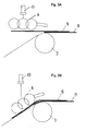
- FIG. 1 A first variant of the device is shown in FIG.
- the sheets B am higher end of the inclined feed table 1 will be about horizontally above the surface of one forming a feed plane 5 Sheet stack of a sheet feeder 1 fed.
- Can on the feed side tiltable stops 6A may be provided, which are only indicated here. This Stops 6A release the sheet path from the sheet stack to the belt roll 3.
- the Forward movement of the sheet to the feed table 1 is not shown here, intermittently adjustable dab rollers on the belt roller.
- the arc B is clamped between the belt roller 3 and the dab rollers and through the rotation of the belt roll 3 moves forward.
- the dab rollers only work at the belt roller 3.
- a additional conveyor roller 6 can be arranged upstream of the belt roller 3. Then they work Conveyor rollers together with this conveyor roller. The sheets B are then on higher end of the inclined feed table 1 of the Sheet feeder fed to the belt roller 3 over a bridging level. The Bridging level then forms the feed level 5, which in the invention of Meaning is.
- the deflection rollers 8 consist of a bracket 11 and pulleys 9, which on the bracket 11 mutually are attached.
- the center distance of the deflection wheels 9 is selected so that the Contours of the deflection wheels 9 overlap somewhat. This creates the Underside of the deflection rollers 8 a quasi-continuous guide surface.
- the Deflection wheels 9 can on the bracket 11 in the direction of their connection Axes of rotation, at least above the belt roller 3, are approximately arch-shaped be arranged.
- the bracket 11 together with the deflection wheels 9 are in one Pneumatic cylinder 13 attached.
- the pneumatic cylinder 13 is double-acting and via its connections with a pneumatic valve, not shown here connected.
- the pneumatic valve can be controlled remotely and with the Machine control connected.
- the pneumatic valve also has a Switching option to change the operating pressure and thus the Contact force of the pneumatic cylinder 13 in the setting position compared to the Feed table 1 on.
- the pneumatic cylinder 13 can directly on the deflection rollers 8 carry his piston rod.
- the deflection rollers 8 can also on their Bracket 11 on a swivel arm 10 about an axis 14 relative to the feed table 1 can be arranged pivotably.
- the adjustment of the pneumatic cylinder 13 can also by means of the control valve be continuously variable. Then can be sensitive to different Printing materials the appropriate reduced contact pressure can be selected. Likewise Depending on the stiffness of the substrate, the increased contact pressure required be adjusted.
Landscapes
- Engineering & Computer Science (AREA)
- Mechanical Engineering (AREA)
- Delivering By Means Of Belts And Rollers (AREA)
- Sheets, Magazines, And Separation Thereof (AREA)
- Separation, Sorting, Adjustment, Or Bending Of Sheets To Be Conveyed (AREA)
- Electrical Discharge Machining, Electrochemical Machining, And Combined Machining (AREA)
- Valve Device For Special Equipments (AREA)
Abstract
Description
Die Umlenkrollen sind vorteilhafterweise in ihrer Ruhestellung senkrecht zur Ebene der Zuführebene oberhalb deren angeordnet. Sie sind geradlinig oder um einen Gelenkpunkt schwenkbar beweglich geführt.
Zum Anstellen der Umlenkrollen ist ein Stellantrieb vorgesehen, der mit der Steuerung der Bogen verarbeitenden Maschine bzw. des Bogenanlegers verbunden ist. Der Stellantrieb ist vorteilhafterweise mit einer Steuereinrichtung zur Veränderung der auf die Umlenkrollen wirkenden Kraft versehen.
- Fig. 1
- eine erste Ausführungsform der erfindungsgemäßen Vorrichtung;
- Fig. 2
- eine zweite Ausführungsform der erfindungsgemäßen Vorrichtung und
- Fig. 3A und 3B
- Funktionsskizzen zum erfindungsgemäßen Verfahren.
- 1
- Anlegetisch
- 2
- Förderrichtung
- 3
- Bänderwalze
- 4
- Förderband
- 5
- Zuführebene
- 6
- Förderwalze
- 7
- Knickstelle
- 8
- Umlenkrollen
- 9
- Umlenkrad
- 10
- Schwenkarm
- 11
- Halterung
- 12
- Kolbenstange
- 13
- Pneumatikzylinder
- 14
- Achse
- 15
- Kolben
- 16
- Tupfrolle
Claims (9)
- Verfahren zum Zuführen von Bogen zu einer Bogen verarbeitenden Maschine durch unterschupptes Zuführen von Bogen von einem Bogenanleger in einer im wesenlichen horizontalen Ebene zu einem dazu abwärts geneigten Anlegetisch, vorzugweise einem Saugbändertisch, über eine durch die Zuführebene und die Ebene des Anlegetisches definierte Knickstelle, durch Umlenken des unterschuppten Bogenstroms mittels Umlenkrollen an der Knickstelle aus der Zuführebene in die Ebene des Anlegetisches,indem die Umlenkrollen zu Beginn der Zuführung von Bogen angehoben werden, derart dass der Bogenstrom wenigsten für die Dauer der Förderung eines Bogens unbeeinflusst bleibt,indem durch Anstellen der Umlenkrollen gegen die die Knickstelle überragenden Bogen auf den Anlegetisch niedergedrückt werden,indem durch Anstellen der Umlenkrollen mit erhöhter Kraft die Haftung des Bogenstroms an den Fördermitteln des Anlegetisches hergestellt wird undindem durch Reduzierung der Anstellkraft der Umlenkrollen spätestens bei Ankunft der ersten Bogen in der Bogen verarbeitenden Maschine die kontinuierliche Bogenzufuhr zum Saugbändertisch gewährleistet wird.
- Anlegetisch zur Durchführung des Verfahrens nach Anspruch 1 zum Anlegen von Bogen an eine bogenverarbeitende Maschine, insbesondere eine Druckmaschine, dem Bogen von einem Bogenanleger in einer etwa horizontalen Zuführebene zuführbar sind und der gegenüber der Zuführebene geneigt ist, wobei etwa über dem Bereich der Knickstelle zwischen Zuführebene und Anlegetisch eine oder mehrere Umlenkrollen angeordnet sind, durch die die Bogen aus der Zuführebene in die Ebene des Anlegetischs umlenkbar sind, und wobei die Umlenkrollen mittels eines Stellantriebes mit gegen den Anlegetisch anstellbar sind,
dadurch gekennzeichnet, dass als Anlegetisch ein Saugbändertisch vorgesehen ist, dass der Stellantrieb mit einer Steuerung zum An- und Abstellen der Umlenkrollen vom Saugbändertisch versehen ist, dass die Steuerung mit der Maschinensteuerung der Bogen verarbeitenden Maschine verbunden ist, wobei die Umlenkrollen derart angeordnet sind, dass sie zu Förderbeginn in eine Ruhestellung oberhalb der horizontalen Zuführebene abstellbar sind, dass der Stellantrieb nach Zufuhr von wenigstens zwei unterschuppt liegenden Bogen bis zur Knickstelle zwischen Zuführebene und Saugbändertisch aktivierbar ist, derart dass die Umlenkrollen mit einer ersten erhöhten Kraft gegen den Saugbändertisch anstellbar sind und dass die Anstellkraft nach Erfassung der Bogen durch den Saugbändertisch auf ein zweites Maß reduzierbar ist. - Vorrichtung nach Anspruch 2,
dadurch gekennzeichnet, dass ein oder mehrere pneumatische Stellantriebe, vorzugsweise Pneumatikzylinder, vorgesehen sind und dass pneumatische Steuermittel zum fernsteuerbaren Betrieb der Stellantriebe in An- und Abstellrichtung und zur, stufenweisen oder kontinuierlichen, Veränderung des Betriebsdruckes des bzw. der pneumatischen Stellantriebe vorgesehen sind. - Vorrichtung nach Anspruch 3,
dadurch gekennzeichnet; dass wenigstens ein Pneumatikventil vorgesehen ist, mittels dessen der bzw. die Stellantriebe in Abstellposition der Umlenkrollen, sowie in Anstellposition mit erhöhtem Anstelldruck und reduziertem Anstelldruck ansteuerbar sind. - Anlegetisch nach Anspruch 4,
dadurch gekennzeichnet, dass mehrere Umlenkrollen derart angeordnet sind, dass sie eine vorzugsweise nicht gekrümmte Leitebene bilden, und dass die Umlenkrollen frei drehbar gelagert sind. - Anlegetisch nach einem der vorhergehenden Ansprüche,
dadurch gekennzeichnet, dass die Umlenkrollen als Umlenkräder (9) ausgebildet sind und dass die Umlenkräder (9) in Förderrichtung (2) der Bogen (B) hintereinander an einem Ende eines Halters (8, 10) angeordnet sind. - Anlegetisch nach Anspruch 5,
dadurch gekennzeichnet, dass die Umlenkräder (9) an dem Halter (8, 10) derart angeordnet sind, dass die Konturen jeweils zweier in Bogenlaufrichtung hintereinander liegender Umlenkräder (9) sich überschneiden. - Anlegetisch nach einem der vorhergehenden Ansprüche,
dadurch gekennzeichnet, dass quer zur Förderrichtung (2) im Abstand nebeneinander mehrere Halter (8, 10) mit Umlenkrädern (9) angeordnet sind. - Anlegetisch nach einem der vorhergehenden Ansprüche,
dadurch gekennzeichnet, dass pro Saugband des Saugbändertisches ein Halter (8, 10) mit Umlenkrädern (9) angeordnet ist.
Applications Claiming Priority (2)
| Application Number | Priority Date | Filing Date | Title |
|---|---|---|---|
| DE10129007 | 2001-06-15 | ||
| DE10129007A DE10129007C1 (de) | 2001-06-15 | 2001-06-15 | Vorrichtung zum unterschuppten Zuführen von Bogen |
Publications (3)
| Publication Number | Publication Date |
|---|---|
| EP1266850A2 true EP1266850A2 (de) | 2002-12-18 |
| EP1266850A3 EP1266850A3 (de) | 2004-04-21 |
| EP1266850B1 EP1266850B1 (de) | 2006-01-04 |
Family
ID=7688363
Family Applications (1)
| Application Number | Title | Priority Date | Filing Date |
|---|---|---|---|
| EP02012209A Expired - Lifetime EP1266850B1 (de) | 2001-06-15 | 2002-06-04 | Anlegetisch |
Country Status (3)
| Country | Link |
|---|---|
| EP (1) | EP1266850B1 (de) |
| AT (1) | ATE314989T1 (de) |
| DE (2) | DE10129007C1 (de) |
Cited By (2)
| Publication number | Priority date | Publication date | Assignee | Title |
|---|---|---|---|---|
| WO2013045813A1 (fr) | 2011-09-27 | 2013-04-04 | Sidel Participations | Dispositif de transfert de decoupes |
| CN115352914A (zh) * | 2022-08-15 | 2022-11-18 | 兆虹精密(北京)科技有限公司 | 捋纸机构及铺纸机 |
Family Cites Families (3)
| Publication number | Priority date | Publication date | Assignee | Title |
|---|---|---|---|---|
| DE19618870A1 (de) * | 1996-05-10 | 1997-11-13 | Heidelberger Druckmasch Ag | Vorrichtung zum Fördern eines insbesondere geschuppten Stroms von Bogen zu einer bogenverarbeitenden Maschine |
| DE29704796U1 (de) * | 1997-03-15 | 1997-05-28 | MAN Roland Druckmaschinen AG, 63075 Offenbach | Anlegetisch |
| DE29900995U1 (de) * | 1999-01-21 | 1999-04-01 | MAN Roland Druckmaschinen AG, 63075 Offenbach | Anlegetisch |
-
2001
- 2001-06-15 DE DE10129007A patent/DE10129007C1/de not_active Expired - Fee Related
-
2002
- 2002-06-04 AT AT02012209T patent/ATE314989T1/de active
- 2002-06-04 DE DE50205497T patent/DE50205497D1/de not_active Expired - Lifetime
- 2002-06-04 EP EP02012209A patent/EP1266850B1/de not_active Expired - Lifetime
Cited By (2)
| Publication number | Priority date | Publication date | Assignee | Title |
|---|---|---|---|---|
| WO2013045813A1 (fr) | 2011-09-27 | 2013-04-04 | Sidel Participations | Dispositif de transfert de decoupes |
| CN115352914A (zh) * | 2022-08-15 | 2022-11-18 | 兆虹精密(北京)科技有限公司 | 捋纸机构及铺纸机 |
Also Published As
| Publication number | Publication date |
|---|---|
| ATE314989T1 (de) | 2006-02-15 |
| DE10129007C1 (de) | 2002-10-17 |
| EP1266850A3 (de) | 2004-04-21 |
| EP1266850B1 (de) | 2006-01-04 |
| DE50205497D1 (de) | 2006-03-30 |
Similar Documents
| Publication | Publication Date | Title |
|---|---|---|
| DE2922450C2 (de) | Vorrichtung zum Wegfördern von in einem Schuppenstrom anfallenden flächigen Erzeugnissen, insbesondere Druckprodukten | |
| CH660353A5 (de) | Verfahren und vorrichtung zum unterteilen eines schuppenstromes aus druckbogen in teilschuppen. | |
| WO2003070465A1 (de) | Vorrichtung zum transport von bogen mit einem bogenleitelement | |
| EP0606550A1 (de) | Vorrichtung zum Zubringen von flächigen Erzeugnissen zu einer Verarbeitungseinrichtung für Druckereiprodukte | |
| DE2639676C2 (de) | Vorrichtung zum Beschicken eines Rundstapelbogenanlegers | |
| EP0606549B1 (de) | Vorrichtung zum Transportieren von flächigen Erzeugnissen | |
| EP0101025B1 (de) | Wendeeinrichtung in einer Förderstrecke zwischen zwei Bearbeitungsmaschinen | |
| DE1786232A1 (de) | Bogenanleger fuer bogenverarbeitende Maschinen | |
| EP0103104B1 (de) | Vorrichtung zum Fördern von Bogen oder Bogenpaketen | |
| EP1041028B1 (de) | Ausleger einer Bogen verarbeitenden Druckmaschine | |
| DE4439092C2 (de) | Vorrichtung zum Zuführen von Bogen | |
| EP0708050B1 (de) | Kabeltransport- und Schwenkvorrichtung | |
| DE4239254C2 (de) | Einrichtung zum Einstellen der Anlegmarken | |
| EP0755886B1 (de) | Vorrichtung zum Zubringen von Druckereiprodukten zu einer Weiterverarbeitungsstelle | |
| DE10129007C1 (de) | Vorrichtung zum unterschuppten Zuführen von Bogen | |
| EP1022244B1 (de) | Anlegetisch | |
| EP1010525B1 (de) | Bogenführungseinrichtung für eine Druckmaschine | |
| DE2440106B2 (de) | Vorrichtung zum Auftragen von Klebstoff | |
| EP0863099A1 (de) | Einrichtung zum Vereinzeln gestapelter Druckereiprodukte | |
| DE10106669B4 (de) | Einrichtung zur Ablage von Bogen | |
| EP1136262B1 (de) | Vorrichtung für den Antrieb eines Vorgreifers | |
| EP1414728B1 (de) | Vorrichtung zur ausrichtung von in einer lage übereinander angeordneten bogen | |
| DE19828625A1 (de) | Maschine und Verfahren zum kontinuierlichen Falzen von Papierbogen, insbesondere für die Herstellung von gefalzten Signaturen | |
| DE4016304A1 (de) | Vorrichtung zum ausrichten schuppenfoermig unterlappt gefoerderter bogen | |
| EP1352862B1 (de) | Verfahren zum wahlweisen Zuführen von Bogen oder Vorlaufbogen |
Legal Events
| Date | Code | Title | Description |
|---|---|---|---|
| PUAI | Public reference made under article 153(3) epc to a published international application that has entered the european phase |
Free format text: ORIGINAL CODE: 0009012 |
|
| AK | Designated contracting states |
Kind code of ref document: A2 Designated state(s): AT BE CH CY DE DK ES FI FR GB GR IE IT LI LU MC NL PT SE TR |
|
| AX | Request for extension of the european patent |
Free format text: AL;LT;LV;MK;RO;SI |
|
| PUAL | Search report despatched |
Free format text: ORIGINAL CODE: 0009013 |
|
| AK | Designated contracting states |
Kind code of ref document: A3 Designated state(s): AT BE CH CY DE DK ES FI FR GB GR IE IT LI LU MC NL PT SE TR |
|
| AX | Request for extension of the european patent |
Extension state: AL LT LV MK RO SI |
|
| RIC1 | Information provided on ipc code assigned before grant |
Ipc: 7B 65H 11/00 A Ipc: 7B 65H 5/06 B |
|
| 17P | Request for examination filed |
Effective date: 20040312 |
|
| AKX | Designation fees paid |
Designated state(s): AT BE CH CY DE DK ES FI FR GB GR IE IT LI LU MC NL PT SE TR |
|
| 17Q | First examination report despatched |
Effective date: 20050311 |
|
| GRAP | Despatch of communication of intention to grant a patent |
Free format text: ORIGINAL CODE: EPIDOSNIGR1 |
|
| GRAS | Grant fee paid |
Free format text: ORIGINAL CODE: EPIDOSNIGR3 |
|
| RIN1 | Information on inventor provided before grant (corrected) |
Inventor name: ULLRICH, BERND Inventor name: MOELLER, JUERGEN Inventor name: CUCCHIARA, GIUSEPPE Inventor name: ROESSLER, MICHAEL Inventor name: WALTHER, THOMAS Inventor name: HERRMANN, DETLEV |
|
| GRAA | (expected) grant |
Free format text: ORIGINAL CODE: 0009210 |
|
| AK | Designated contracting states |
Kind code of ref document: B1 Designated state(s): AT BE CH CY DE DK ES FI FR GB GR IE IT LI LU MC NL PT SE TR |
|
| PG25 | Lapsed in a contracting state [announced via postgrant information from national office to epo] |
Ref country code: IT Free format text: LAPSE BECAUSE OF FAILURE TO SUBMIT A TRANSLATION OF THE DESCRIPTION OR TO PAY THE FEE WITHIN THE PRE;WARNING: LAPSES OF ITALIAN PATENTS WITH EFFECTIVE DATE BEFORE 2007 MAY HAVE OCCURRED AT ANY TIME BEFORE 2007. THE CORRECT EFFECTIVE DATE MAY BE DIFFERENT FROM THE ONE RECORDED.SCRIBED TIME-LIMIT Effective date: 20060104 Ref country code: GB Free format text: LAPSE BECAUSE OF FAILURE TO SUBMIT A TRANSLATION OF THE DESCRIPTION OR TO PAY THE FEE WITHIN THE PRESCRIBED TIME-LIMIT Effective date: 20060104 Ref country code: NL Free format text: LAPSE BECAUSE OF FAILURE TO SUBMIT A TRANSLATION OF THE DESCRIPTION OR TO PAY THE FEE WITHIN THE PRESCRIBED TIME-LIMIT Effective date: 20060104 Ref country code: IE Free format text: LAPSE BECAUSE OF FAILURE TO SUBMIT A TRANSLATION OF THE DESCRIPTION OR TO PAY THE FEE WITHIN THE PRESCRIBED TIME-LIMIT Effective date: 20060104 Ref country code: FI Free format text: LAPSE BECAUSE OF FAILURE TO SUBMIT A TRANSLATION OF THE DESCRIPTION OR TO PAY THE FEE WITHIN THE PRESCRIBED TIME-LIMIT Effective date: 20060104 |
|
| REG | Reference to a national code |
Ref country code: GB Ref legal event code: FG4D Free format text: NOT ENGLISH |
|
| REG | Reference to a national code |
Ref country code: CH Ref legal event code: EP |
|
| REG | Reference to a national code |
Ref country code: IE Ref legal event code: FG4D Free format text: LANGUAGE OF EP DOCUMENT: GERMAN |
|
| REF | Corresponds to: |
Ref document number: 50205497 Country of ref document: DE Date of ref document: 20060330 Kind code of ref document: P |
|
| PG25 | Lapsed in a contracting state [announced via postgrant information from national office to epo] |
Ref country code: DK Free format text: LAPSE BECAUSE OF FAILURE TO SUBMIT A TRANSLATION OF THE DESCRIPTION OR TO PAY THE FEE WITHIN THE PRESCRIBED TIME-LIMIT Effective date: 20060404 Ref country code: SE Free format text: LAPSE BECAUSE OF FAILURE TO SUBMIT A TRANSLATION OF THE DESCRIPTION OR TO PAY THE FEE WITHIN THE PRESCRIBED TIME-LIMIT Effective date: 20060404 |
|
| PG25 | Lapsed in a contracting state [announced via postgrant information from national office to epo] |
Ref country code: ES Free format text: LAPSE BECAUSE OF FAILURE TO SUBMIT A TRANSLATION OF THE DESCRIPTION OR TO PAY THE FEE WITHIN THE PRESCRIBED TIME-LIMIT Effective date: 20060415 |
|
| PG25 | Lapsed in a contracting state [announced via postgrant information from national office to epo] |
Ref country code: PT Free format text: LAPSE BECAUSE OF FAILURE TO SUBMIT A TRANSLATION OF THE DESCRIPTION OR TO PAY THE FEE WITHIN THE PRESCRIBED TIME-LIMIT Effective date: 20060605 |
|
| PG25 | Lapsed in a contracting state [announced via postgrant information from national office to epo] |
Ref country code: MC Free format text: LAPSE BECAUSE OF NON-PAYMENT OF DUE FEES Effective date: 20060630 Ref country code: LI Free format text: LAPSE BECAUSE OF NON-PAYMENT OF DUE FEES Effective date: 20060630 Ref country code: BE Free format text: LAPSE BECAUSE OF NON-PAYMENT OF DUE FEES Effective date: 20060630 Ref country code: CH Free format text: LAPSE BECAUSE OF NON-PAYMENT OF DUE FEES Effective date: 20060630 |
|
| NLV1 | Nl: lapsed or annulled due to failure to fulfill the requirements of art. 29p and 29m of the patents act | ||
| GBV | Gb: ep patent (uk) treated as always having been void in accordance with gb section 77(7)/1977 [no translation filed] |
Effective date: 20060104 |
|
| REG | Reference to a national code |
Ref country code: IE Ref legal event code: FD4D |
|
| PLBE | No opposition filed within time limit |
Free format text: ORIGINAL CODE: 0009261 |
|
| STAA | Information on the status of an ep patent application or granted ep patent |
Free format text: STATUS: NO OPPOSITION FILED WITHIN TIME LIMIT |
|
| 26N | No opposition filed |
Effective date: 20061005 |
|
| REG | Reference to a national code |
Ref country code: CH Ref legal event code: PL |
|
| EN | Fr: translation not filed | ||
| BERE | Be: lapsed |
Owner name: MAN ROLAND DRUCKMASCHINEN A.G. Effective date: 20060630 |
|
| PG25 | Lapsed in a contracting state [announced via postgrant information from national office to epo] |
Ref country code: GR Free format text: LAPSE BECAUSE OF FAILURE TO SUBMIT A TRANSLATION OF THE DESCRIPTION OR TO PAY THE FEE WITHIN THE PRESCRIBED TIME-LIMIT Effective date: 20060405 Ref country code: FR Free format text: LAPSE BECAUSE OF FAILURE TO SUBMIT A TRANSLATION OF THE DESCRIPTION OR TO PAY THE FEE WITHIN THE PRESCRIBED TIME-LIMIT Effective date: 20070223 |
|
| PG25 | Lapsed in a contracting state [announced via postgrant information from national office to epo] |
Ref country code: LU Free format text: LAPSE BECAUSE OF NON-PAYMENT OF DUE FEES Effective date: 20060604 Ref country code: TR Free format text: LAPSE BECAUSE OF FAILURE TO SUBMIT A TRANSLATION OF THE DESCRIPTION OR TO PAY THE FEE WITHIN THE PRESCRIBED TIME-LIMIT Effective date: 20060104 |
|
| PG25 | Lapsed in a contracting state [announced via postgrant information from national office to epo] |
Ref country code: CY Free format text: LAPSE BECAUSE OF FAILURE TO SUBMIT A TRANSLATION OF THE DESCRIPTION OR TO PAY THE FEE WITHIN THE PRESCRIBED TIME-LIMIT Effective date: 20060104 Ref country code: FR Free format text: LAPSE BECAUSE OF FAILURE TO SUBMIT A TRANSLATION OF THE DESCRIPTION OR TO PAY THE FEE WITHIN THE PRESCRIBED TIME-LIMIT Effective date: 20060104 |
|
| REG | Reference to a national code |
Ref country code: DE Ref legal event code: R081 Ref document number: 50205497 Country of ref document: DE Owner name: MANROLAND SHEETFED GMBH, DE Free format text: FORMER OWNER: MANROLAND AG, 63075 OFFENBACH, DE Effective date: 20120509 |
|
| PGFP | Annual fee paid to national office [announced via postgrant information from national office to epo] |
Ref country code: AT Payment date: 20120613 Year of fee payment: 11 |
|
| REG | Reference to a national code |
Ref country code: AT Ref legal event code: PC Ref document number: 314989 Country of ref document: AT Kind code of ref document: T Owner name: MANROLAND SHEETFED GMBH, DE Effective date: 20130906 |
|
| REG | Reference to a national code |
Ref country code: AT Ref legal event code: MM01 Ref document number: 314989 Country of ref document: AT Kind code of ref document: T Effective date: 20140604 |
|
| PG25 | Lapsed in a contracting state [announced via postgrant information from national office to epo] |
Ref country code: AT Free format text: LAPSE BECAUSE OF NON-PAYMENT OF DUE FEES Effective date: 20140604 |
|
| PGFP | Annual fee paid to national office [announced via postgrant information from national office to epo] |
Ref country code: DE Payment date: 20150619 Year of fee payment: 14 |
|
| REG | Reference to a national code |
Ref country code: DE Ref legal event code: R119 Ref document number: 50205497 Country of ref document: DE |
|
| PG25 | Lapsed in a contracting state [announced via postgrant information from national office to epo] |
Ref country code: DE Free format text: LAPSE BECAUSE OF NON-PAYMENT OF DUE FEES Effective date: 20170103 |