EP1267091A2 - Querelement mit einem konischen Halsabschnitt - Google Patents
Querelement mit einem konischen Halsabschnitt Download PDFInfo
- Publication number
- EP1267091A2 EP1267091A2 EP02077284A EP02077284A EP1267091A2 EP 1267091 A2 EP1267091 A2 EP 1267091A2 EP 02077284 A EP02077284 A EP 02077284A EP 02077284 A EP02077284 A EP 02077284A EP 1267091 A2 EP1267091 A2 EP 1267091A2
- Authority
- EP
- European Patent Office
- Prior art keywords
- transverse element
- transverse
- neck portion
- drive belt
- supporting
- Prior art date
- Legal status (The legal status is an assumption and is not a legal conclusion. Google has not performed a legal analysis and makes no representation as to the accuracy of the status listed.)
- Granted
Links
- 230000007704 transition Effects 0.000 claims abstract description 21
- 230000005540 biological transmission Effects 0.000 claims abstract description 20
- 239000000969 carrier Substances 0.000 claims abstract description 13
- 238000006073 displacement reaction Methods 0.000 claims description 18
- 238000000034 method Methods 0.000 description 5
- 238000004080 punching Methods 0.000 description 4
- 230000015572 biosynthetic process Effects 0.000 description 3
- 238000004519 manufacturing process Methods 0.000 description 3
- 238000012986 modification Methods 0.000 description 1
- 230000004048 modification Effects 0.000 description 1
- 238000005096 rolling process Methods 0.000 description 1
Images


Classifications
-
- F—MECHANICAL ENGINEERING; LIGHTING; HEATING; WEAPONS; BLASTING
- F16—ENGINEERING ELEMENTS AND UNITS; GENERAL MEASURES FOR PRODUCING AND MAINTAINING EFFECTIVE FUNCTIONING OF MACHINES OR INSTALLATIONS; THERMAL INSULATION IN GENERAL
- F16G—BELTS, CABLES, OR ROPES, PREDOMINANTLY USED FOR DRIVING PURPOSES; CHAINS; FITTINGS PREDOMINANTLY USED THEREFOR
- F16G5/00—V-belts, i.e. belts of tapered cross-section
- F16G5/16—V-belts, i.e. belts of tapered cross-section consisting of several parts
Definitions
- the present invention relates to a transverse element for a drive belt for a continuously variable transmission having two pulleys having an at least partially conical contact surface for pairwise enclosing of the drive belt, each pulley being composed of two pulley sheaves, the drive belt comprising two endless carriers and transverse elements which are placed against each other in axial direction of the drive belt, wherein the transverse elements on both sides are provided with a supporting surface for supporting a carrier, which supporting surface on the one side turns into a pulley sheave contact surface being designed to abut against a contact surface of a pulley sheave and on the other side into a side surface of a neck portion of the transverse element, through a transition region.
- Such a transverse element is generally known, and is designed for application in a drive belt for a continuously variable transmission.
- a drive belt comprises two bundles of endless bands being shaped like a closed loop, which function as carriers of a number of transverse elements.
- the transverse elements are continuously arranged along the entire length of the bands, in order for them to be able to transmit forces which are related to a movement of the drive belt during operation.
- the transverse element is on both sides provided with recesses for at least partially receiving the bundles of bands.
- a portion of the inner surface of a recess forms a supporting surface for supporting a bundle of bands.
- the transverse elements on both sides are provided with pulley sheave contact surfaces which are divergent in the direction of the supporting surfaces.
- a supporting surface is on the one side connected to a pulley sheave contact surface and on the other side to a side surface of a neck portion of the transverse element, through a transition region.
- Said neck portion comprises the portion of the transverse element being situated between the recesses.
- the transverse element comprises an inner portion and an outer portion, wherein the inner portion comprises the supporting surfaces and the pulley sheave contact surfaces.
- the transverse element is positioned such that the inner portion is located at the inner circumference of the drive belt and the outer portion is located at the outer circumference of the drive belt.
- a projection is arranged on a front surface of the outer portion, while a hole is arranged in a back surface of the outer portion.
- the positions and the dimensions of the projection and the hole are adapted to each other in such a way that the projection of a transverse element can be received by the hole of a subsequent transverse element.
- An important function of the projections and the holes is preventing a mutual displacement in transverse direction of subsequent transverse elements which are part of a drive belt.
- the dimensions of the outer portion are also determined by the projection and the hole.
- the projection and the hole are preferably formed in the outer portion with the help of a die and a corresponding mould during a manufacturing process for forming the transverse element, like the punching process.
- a certain surface surrounding the projection and the hole which in this case is called the fixture surface, is necessary for obtaining a sufficiently strong die and mould and for sufficiently supporting the transverse element during the formation of the projection and the hole.
- the transverse element needs to posses a certain strength being suitable for utilisation thereof in the drive belt.
- the transverse element is designed for application in a drive belt for a continuously variable transmission.
- the continuously variable transmission can for example be designed to be build into a motor vehicle. It is therefore desired that the weight of the transverse element is a low as possible, while the transverse element has to be sufficiently strong to absorb the forces which occur during operation of the continuously variable transmission.
- a transverse element according to the invention is characterized in that at least a portion of the neck portion tapers towards the supporting surfaces.
- the tapered layout of the neck portion results in the outer portion and the inner portion being able to be smaller, whereby the weight of the transverse element is lower relative to a known transverse element being provided with a neck portion, the side surfaces of which extend substantially parallel relative to each other.
- said tapered layout is such that the neck portion is relatively large at the side of the outer portion.
- the fixture surface being situated around the projection and the hole, which amongst others is necessary for being able to obtain a sufficiently strong die and mould and for being able to sufficiently support the transverse element during the formation of the projection and the hole, can then also be displaced in the direction of the neck portion, so that a portion of the outer portion can be removed.
- a portion of the inner portion needs then also to be removed. The weight-saving is achieved, because the portion which is added to the neck portion is smaller than the total portion which can be removed at the outer portion and the inner portion.
- JP04083941 a transverse element and a bundle of bands are being disclosed, wherein an angle is defined between a position of a standing side of the bundle of bands when this is in a normal position on the supporting surface of the transverse element, and a position of said standing side when the bundle of bands has undergone an angular displacement relative to the normal position.
- angular displacement can be described as a rotation of the transverse element about the centre of its projection relative to the bundle of bands.
- the position is chosen to be such that on an angular displacement in transverse direction of the bundle of bands, contact between a standing side of the bundle of bands and the side surface of the neck portion of the transverse element can take place through a plane, whereby the chance of damage of said side surface is reduced.
- the side surface is at an angle with an imaginary line extending perpendicular relative to the supporting surface, which angle equals the angle being present between the bands at a maximum angular displacement in transverse direction and the supporting surface. Generally, this latter angle is approximately 1° to 2°. It will be clear that the maximum angular displacement of the bundle of bands is determined by the width and the height of the bundle of bands and the width and the height of the recess.
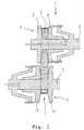
- Figure 1 shows diagrammatically a continuously variable transmission, such as for utilisation in a motor vehicle.
- the continuously variable transmission is indicated in general by the reference sign 1.
- the continuously variable transmission 1 comprises two pulleys 4 and 5 being arranged on separate pulley shafts 2 and 3.
- An endless drive belt 6 being shaped like a closed loop is arranged around the pulleys 4 and 5 and serves for transmitting torque between the pulley shafts 2 and 3.
- the pulleys 4 and 5 are each provided with two conical sheaves 7 and 8 respectively 9 and 10, which collectively form a partially conical receiving groove 11 in which the drive belt 6 is received.
- the transmission ratio of the continuously variable transmission 1 is determined by the ratio of the running radii of the drive belt 6 in the receiving groove 11 of the pulleys 4 and 5.
- the running radii can be varied by mutually displacing the pulley sheaves 7 and 8 respectively 9 and 10 with the help of displacing means, which are not depicted for the sake of the simplicity.
- at least one of the pulley sheaves 7 and 8 respectively 9 and 10 is arranged in an axially movable manner.
- the drive belt 6 is clamped inside the receiving groove 11 of the pulleys 4 and 5 with a certain clamping force.
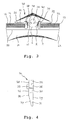
- the drive belt 6 is depicted in more detail.
- the drive belt 6 comprises two endless carriers 12 being disposed next to each other, which in this example are each composed of a number of bands 13 forming a bundle of bands 14.
- transverse elements 20 are arranged, wherein the transverse elements 20 are mutually adjacent to each other and are movable in axial direction relative to the carriers 12.
- FIG 2 only a few of these transverse elements 20 are shown.
- the carriers 12 and the transverse element 20 are depicted in transverse view.
- the transverse element 20 is on both sides provided with recesses 21 in which the bundles of bands 14 are partially received.
- the transverse element 20 comprises on both sides supporting surfaces 22 on which the bundles of bands 14 are supported.
- the transverse element 20 comprises on both sides pulley sheave contact surfaces 23.
- the transverse element 20 When the transverse element 20 is inside the receiving groove 11, contact between the transverse element 20 and a contact surface of the pulley sheave 7, 8, 9, 10 is established through said pulley sheave contact surface 23.
- the portion of the transverse element 20 being situated between the highest point of the surface 22 and the lowest point of the surface 39, being depicted by discontinuous lines in the figure, is indicated in the following as neck portion 30.
- the inner portion 31 comprises the supporting surfaces 22 and the pulley sheave contact surfaces 23, and is located at the inner circumference of the drive belt 6 on utilisation of the transverse element 20 in the drive belt 6.
- the portion of the transverse element 20 being situated above the neck portion 30 in figure 3, is indicated in the following as outer portion 32.
- the outer portion 32 is located at the outer circumference of the drive belt 6 on utilisation of the transverse element 20 in the drive belt 6.
- Two subsequent transverse elements 20 are tiltable relative to each other about a contact line 25.
- the contact line 25 is situated at the position where a slanting portion 27 of a front surface 26 of the transverse element 20 is connected to a straight portion 28 of said front surface 26.
- a projection 35 is arranged on the front surface 26.
- said projection 35 is cylindrical.
- a hole 36 is arranged in a back surface 29. The dimensions and the positions of the projection 35 and the hole 36 are adapted to each other in such a way that the projection 35 of a transverse element 20 can be received by the hole 36 of a subsequent transverse element 20.
- An important function of the projection 35 and the hole 36 is preventing a mutual displacement of subsequent transverse elements 20 which are part of the drive belt 6.
- Both the projection 35 and the hole 36 are preferably formed by means of a die and a mould (not shown), like for example a punching process. In the process, a certain surface surrounding the projection 35 and the hole 36 is necessary for being able to obtain a sufficiently strong die and mould and for being able to sufficiently support the transverse element 20 during the formation of the projection 35 and the hole 36. Moreover, the transverse element 20 needs to posses a certain strength being suitable for utilisation thereof in the drive belt 6.
- the delimitation of this fixture surface is diagrammatically depicted by means of the dashed line being indicated by c in figure 3.
- the delimitation c has the shape of a circle, wherein said circle touches the side surfaces 38 of the neck portion 30 and an outer surface of the outer portion 32.
- the position of the circle is chosen such that its diameter can be as large as possible.
- the projection 35 and the hole 36 are positioned substantially in the centre of the circular fixture surface.
- a supporting surface 22 is connected to a side surface 38 of the neck portion 30, through a lower transition region 37.
- Said lower transition region 37 comprises a portion being deepened relative to the supporting surface 22.
- An important function of the lower transition region 37 is preventing of the bundle of bands 14 of the drive belt 6 being able to come in contact with the side surface 38 of the neck portion 30. Because of the lower transition region 37 being executed as a deepened portion of the supporting surface 22, a surface along which the bundle of bands 14 could creep in the direction of the neck portion 30 is absent at the side of the neck portion 30. Preventing of contact between the bands 13 and the neck portion 30 is very important, because such a contact can be harmful to the bands 13 and the chance of breaking of the bands 13 can increase as a result thereof.
- the outer portion 32 comprises a upper surface 39 being part of the inner surface of the recess 21.
- Said upper surface 39 is connected to the side surface 38 of the neck portion 30, through an upper transition region 40, wherein said upper transition region 40, in this example, comprises a portion being deepened relative to the upper surface 39.
- a layout of the upper transition region 40 having a deepened portion relative to the upper surface 39 is important as regards the space being needed for that purpose.
- the upper transition region 40 in the shape of a deepened portion relative to the upper surface 39 can be left out.
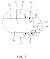
- Figure 5 is a detail of the transverse element 20, wherein a portion of the supporting surface 22, the lower transition region 37, the side surface 38 of the neck portion 30, a portion of the upper surface 39 and the upper transition region 40 are shown.
- the lower transition region 37 comprises a convex portion having a radius R1, at the side of the supporting surface 22. Furthermore, the lower transition region 37 comprises a concave portion having a radius R2. In a similar manner, the upper transition region 40 comprises a convex portion having a radius R3 and a concave portion having a radius R4, at the side of the upper surface 39.
- a value of 0.4 mm or more is chosen for radius R1.
- the fact is, it has appeared in practice that at a value lower than 0.4 mm damage or overload of the inner band 13 of the bundle of bands 14 can occur.
- the radius R2 of the concave portion needs to be sufficiently large. By choosing a value higher than 0.7 mm for radius R2, the chance of breaking of the transverse element 20 is reduced.
- the value of radius R3 is preferably chosen to be the same as the value of radius R1, while the value of radius R4 is preferably chosen to be the same as the value of radius R2.
- an angle is indicated by a, which according to the invention is present between the side surface 38 of the neck portion 30 and an imaginary line 1 being orientated perpendicular to the supporting surface 22.
- the side surface 38 extends parallel relative to the pulley sheave contact surface 23 being situated at the same side of the transverse element 20.
- the angle a has a value of 11°. It is also possible to shape the side surface 38 in a curved way, wherein the side surface 38 preferably has a relatively large radius, such that a smooth connection to the lower transition region 37 and the upper transition region 40 is obtained.
- an angular displacement of the bundles of bands 14 relative to the supporting surfaces 22 can occur.
- This angular displacement is delimited by the upper surface 39 of the outer portion 32.
- the angle a is unequal to the angle being present between the bundles of bands 14 at a maximum angular displacement in transverse direction and the supporting surfaces 22.
- the latter angle is usually approximately 1° to 2°.
- the angle a is larger than the angle being present between the bundles of bands 14 at a maximum angular displacement in transverse direction and the supporting surfaces 22, wherein a side surface 38 of the neck portion 30 and a pulley sheave contact surface 23 being situated at one side of the transverse element 20 extend substantially parallel relative to each other, or wherein said side surface 38 and said pulley sheave contact surface 23 are at a relatively small angle with each other, for example an angle of 3°.
- an angle is indicated by b, which is present between the concave portion of the lower transition region 37 near the supporting surface 22 and said supporting surface 22.
- angle b is smaller than 85°.
- an angle a is present between the side surface 38 of the neck portion 30 and an imaginary line 1 being orientated perpendicular to the supporting surface 22. With this, the neck portion 30 tapers in the direction of the supporting surfaces 22.
- the projection 35 and the hole 36 are preferably positioned substantially in the centre of the fixture surface, the projection 35 and the hole 36 can also be displaced in the direction of the inner portion 31.
- the displacement of the projection 35 is such that the projection 35 is partially situated on the neck portion 30, while in the generally known transverse element, the projection is located solely on the outer portion. It is not essential that the projection 35 is situated partially on the neck portion 30; in any case, it is important that the projection 35 is displaced in the direction of the inner portion 31.
- neck portion 30 tapers. In any case, it is important that a substantial portion of the neck portion 30 at the side of the outer portion 32 is enlarged, by which the above-described displacement of the fixture service can be obtained.
- a first measure relates to adapting the layout of the supporting surface 22.
- the supporting surface 22 is not shaped in a totally flat way, but has a slightly convex layout, as a result of which the bundle of bands 14 will centre itself on said supporting surface 22 during operation of the continuously variable transmission 1.
- the value of the empirical factor f is preferably between 0.0 mm and 0.2 mm. Usually, a value of 0.1 mm is utilised for this factor.
- the value of the angle p is 22°.
- the highest point of the curvature of the supporting surface 22 is displaced along a distance having a size of tan(1 ⁇ 2 * p) * h in the direction of the surface being defined by the pulley sheave contact surface 23.
- the bundle of bands 14 will centre itself on the supporting surface 22 in such a way that a configuration of the bundle of bands 14 as shown in figure 6 is obtained.
- the distance between all bands 13 of the bundle of bands 14 and the side surface 38 of the neck portion 30 is optimal, i.e. as large as possible, as all bands 13 abut against the contact surface of a pulley sheave 7, 8, 9, 10 in an optimal way when the transverse element 20 is inside the receiving groove 11 of a pulley 4, 5.
- a second measure (not illustrated) relates to adapting the layout of the bundle of bands 14.
- a substantially pyramid-shaped bundle of bands 14 can be applied, wherein the transverse dimension of the inner band 13 is the largest, and wherein the transverse dimension of the outer band 13 is the smallest.
- Such a bundle of bands 14 can be manufactured in a simple manner, because all bands 13 are formed from base rings of equal dimensions by means of rolling. When an equal height is adopted for the bands 13, a band 13 having a larger circumference shall get a smaller transverse dimension than a band 13 having a smaller circumference.
Landscapes
- Engineering & Computer Science (AREA)
- General Engineering & Computer Science (AREA)
- Mechanical Engineering (AREA)
- Transmissions By Endless Flexible Members (AREA)
- Diaphragms For Electromechanical Transducers (AREA)
- Dowels (AREA)
Priority Applications (1)
| Application Number | Priority Date | Filing Date | Title |
|---|---|---|---|
| EP11002041A EP2325523A1 (de) | 2001-06-12 | 2002-06-06 | Querelement mit einem konischen Halsabschnitt |
Applications Claiming Priority (2)
| Application Number | Priority Date | Filing Date | Title |
|---|---|---|---|
| NL1018268A NL1018268C2 (nl) | 2001-06-12 | 2001-06-12 | Dwarselement met conisch nekdeel. |
| NL1018268 | 2001-06-12 |
Related Child Applications (1)
| Application Number | Title | Priority Date | Filing Date |
|---|---|---|---|
| EP11002041.9 Division-Into | 2011-03-11 |
Publications (3)
| Publication Number | Publication Date |
|---|---|
| EP1267091A2 true EP1267091A2 (de) | 2002-12-18 |
| EP1267091A3 EP1267091A3 (de) | 2006-04-26 |
| EP1267091B1 EP1267091B1 (de) | 2011-04-27 |
Family
ID=19773531
Family Applications (2)
| Application Number | Title | Priority Date | Filing Date |
|---|---|---|---|
| EP02077284A Expired - Lifetime EP1267091B1 (de) | 2001-06-12 | 2002-06-06 | Querelement mit einem konischen Halsabschnitt |
| EP11002041A Withdrawn EP2325523A1 (de) | 2001-06-12 | 2002-06-06 | Querelement mit einem konischen Halsabschnitt |
Family Applications After (1)
| Application Number | Title | Priority Date | Filing Date |
|---|---|---|---|
| EP11002041A Withdrawn EP2325523A1 (de) | 2001-06-12 | 2002-06-06 | Querelement mit einem konischen Halsabschnitt |
Country Status (6)
| Country | Link |
|---|---|
| US (1) | US6857980B2 (de) |
| EP (2) | EP1267091B1 (de) |
| JP (1) | JP4383022B2 (de) |
| AT (1) | ATE507414T1 (de) |
| DE (1) | DE60239849D1 (de) |
| NL (1) | NL1018268C2 (de) |
Cited By (5)
| Publication number | Priority date | Publication date | Assignee | Title |
|---|---|---|---|---|
| EP1493943A1 (de) * | 2003-07-04 | 2005-01-05 | HONDA MOTOR CO., Ltd. | Riemen für stufenlos regelbares Getriebe |
| EP1645777A1 (de) * | 2004-10-08 | 2006-04-12 | HONDA MOTOR CO., Ltd. | Riemen für ein stufenlos regelbares Getriebe |
| EP1566567A4 (de) * | 2002-11-28 | 2006-08-16 | Honda Motor Co Ltd | Metallriemen für stufenlosen drehzahländerer |
| EP2243980A4 (de) * | 2008-02-15 | 2011-10-05 | Toyota Motor Co Ltd | Element eines riemens für stufenloses getriebe und riemen für stufenloses getriebe |
| NL1043881B1 (en) | 2020-12-24 | 2022-07-20 | Bosch Gmbh Robert | Transverse segment for a drive belt with a carrier ring and multiple transverse segments |
Families Citing this family (11)
| Publication number | Priority date | Publication date | Assignee | Title |
|---|---|---|---|---|
| JP3780237B2 (ja) * | 2002-08-19 | 2006-05-31 | バンドー化学株式会社 | 高負荷伝動用vベルト |
| NL1022022C2 (nl) * | 2002-11-28 | 2004-06-02 | Doornes Transmissie Bv | Metalen drijfriem. |
| ATE519965T1 (de) * | 2003-12-18 | 2011-08-15 | Bosch Gmbh Robert | Treibriemen |
| US20060288969A1 (en) * | 2005-06-22 | 2006-12-28 | Thomas James A | Engine accessory drive using the outside of a two-sided belt to operate a shrouded cooling fan |
| NL1032506C2 (nl) * | 2006-09-15 | 2008-03-18 | Bosch Gmbh Robert | Dwarselement voor een drijfriem voor een continu variabele transmissie. |
| NL1039270C2 (en) * | 2011-12-28 | 2013-07-01 | Bosch Gmbh Robert | Divided blanking member for the purpose of blanking transverse elements for use in a drive belt for a continuously variable transmission. |
| WO2014196254A1 (ja) * | 2013-06-04 | 2014-12-11 | 本田技研工業株式会社 | 無段変速機用金属ベルト |
| JP6506062B2 (ja) * | 2015-03-24 | 2019-04-24 | 本田技研工業株式会社 | 無段変速機用金属エレメントの製造方法 |
| JP6444355B2 (ja) * | 2016-11-04 | 2018-12-26 | 本田技研工業株式会社 | 無段変速機用金属エレメントおよび無段変速機用金属エレメントの製造方法 |
| NL1043501B1 (en) * | 2019-12-10 | 2021-08-31 | Bosch Gmbh Robert | A transverse segment for a drive belt and a drive belt for a continuously variable transmission including the transverse segment and a ring stack |
| CN120457289A (zh) | 2022-12-30 | 2025-08-08 | 罗伯特·博世有限公司 | 用于无级变速器的具有横向构件和环形堆叠的传动带 |
Citations (1)
| Publication number | Priority date | Publication date | Assignee | Title |
|---|---|---|---|---|
| JPH0483941A (ja) | 1990-07-25 | 1992-03-17 | Nissan Motor Co Ltd | 伝動ベルト |
Family Cites Families (7)
| Publication number | Priority date | Publication date | Assignee | Title |
|---|---|---|---|---|
| NL152969C (nl) * | 1973-08-31 | 1983-04-18 | Volvo Car Bv | Drijfband met een trapeziumvormig profiel, bestaande uit een metalen trekband en verschuifbaar daarop aangebrachte metalen dwarselementen. |
| NL155927B (nl) * | 1975-10-09 | 1978-02-15 | Doornes Transmissie Bv | Metalen drijfriem, alsmede duwelement daarvoor. |
| JPS6170246A (ja) * | 1984-09-11 | 1986-04-11 | Nissan Motor Co Ltd | Vベルト |
| JPS6415554A (en) * | 1987-07-08 | 1989-01-19 | Nhk Spring Co Ltd | Block of power transmission belt |
| US4824424A (en) * | 1987-08-24 | 1989-04-25 | Fuji Jukogyo Kabushiki Kaisha | Belt for a belt drive device |
| CA2047048C (en) * | 1990-07-25 | 1996-07-30 | Takashi Masuda | High load force transmission belt |
| JPH05172188A (ja) * | 1991-12-24 | 1993-07-09 | Mitsuboshi Belting Ltd | 高負荷伝動用ベルト |
-
2001
- 2001-06-12 NL NL1018268A patent/NL1018268C2/nl not_active IP Right Cessation
-
2002
- 2002-06-06 EP EP02077284A patent/EP1267091B1/de not_active Expired - Lifetime
- 2002-06-06 AT AT02077284T patent/ATE507414T1/de not_active IP Right Cessation
- 2002-06-06 DE DE60239849T patent/DE60239849D1/de not_active Expired - Lifetime
- 2002-06-06 EP EP11002041A patent/EP2325523A1/de not_active Withdrawn
- 2002-06-10 JP JP2002168052A patent/JP4383022B2/ja not_active Expired - Lifetime
- 2002-06-11 US US10/167,248 patent/US6857980B2/en not_active Expired - Lifetime
Patent Citations (1)
| Publication number | Priority date | Publication date | Assignee | Title |
|---|---|---|---|---|
| JPH0483941A (ja) | 1990-07-25 | 1992-03-17 | Nissan Motor Co Ltd | 伝動ベルト |
Cited By (8)
| Publication number | Priority date | Publication date | Assignee | Title |
|---|---|---|---|---|
| EP1566567A4 (de) * | 2002-11-28 | 2006-08-16 | Honda Motor Co Ltd | Metallriemen für stufenlosen drehzahländerer |
| EP1493943A1 (de) * | 2003-07-04 | 2005-01-05 | HONDA MOTOR CO., Ltd. | Riemen für stufenlos regelbares Getriebe |
| US7282002B2 (en) | 2003-07-04 | 2007-10-16 | Honda Motor Co., Ltd. | Belt for continuously variable transmission |
| CN100465474C (zh) * | 2003-07-04 | 2009-03-04 | 本田技研工业株式会社 | 用于无级变速传动装置的皮带 |
| EP1645777A1 (de) * | 2004-10-08 | 2006-04-12 | HONDA MOTOR CO., Ltd. | Riemen für ein stufenlos regelbares Getriebe |
| US7846049B2 (en) | 2004-10-08 | 2010-12-07 | Honda Motor Co., Ltd. | Belt for continuously variable transmission |
| EP2243980A4 (de) * | 2008-02-15 | 2011-10-05 | Toyota Motor Co Ltd | Element eines riemens für stufenloses getriebe und riemen für stufenloses getriebe |
| NL1043881B1 (en) | 2020-12-24 | 2022-07-20 | Bosch Gmbh Robert | Transverse segment for a drive belt with a carrier ring and multiple transverse segments |
Also Published As
| Publication number | Publication date |
|---|---|
| US6857980B2 (en) | 2005-02-22 |
| NL1018268C2 (nl) | 2002-12-16 |
| DE60239849D1 (de) | 2011-06-09 |
| ATE507414T1 (de) | 2011-05-15 |
| EP1267091B1 (de) | 2011-04-27 |
| US20020187868A1 (en) | 2002-12-12 |
| JP4383022B2 (ja) | 2009-12-16 |
| EP2325523A1 (de) | 2011-05-25 |
| JP2003130139A (ja) | 2003-05-08 |
| EP1267091A3 (de) | 2006-04-26 |
Similar Documents
| Publication | Publication Date | Title |
|---|---|---|
| US6857980B2 (en) | Transverse element having a conical neck portion | |
| US11365783B2 (en) | Transverse segment for a drive belt for a continuously variable transmission and a drive belt and a continuously variable transmission provided therewith | |
| JP4759110B2 (ja) | 連続可変トランスミッションに使用される駆動ベルト | |
| US20190346016A1 (en) | A transverse segment for a drive belt for a continuously variable transmission | |
| JP2003535289A (ja) | 連続可変変速機、トルク伝達のためのしなやかな無端ベルト、そして調整プーリー | |
| EP2061978B1 (de) | Querelement für einen antriebsriemen für ein stufenloses getriebe | |
| EP1221564B1 (de) | Transversale Elemente für Treibriemen mit veränderlicher Berührungslinie | |
| EP2243980A1 (de) | Element eines riemens für stufenloses getriebe und riemen für stufenloses getriebe | |
| US20190032750A1 (en) | Transverse member for a drive belt for a continuously variable transmission | |
| EP2053270B1 (de) | Kraftübertragungskette und Kraftübertragungsvorrichtung | |
| JP2004517273A (ja) | ベルト | |
| US7892126B2 (en) | Transverse element for a drive belt for a continuously variable transmission | |
| EP2053271B1 (de) | Kraftübertragungsvorrichtung | |
| JP2009063164A (ja) | 伝動チェーン | |
| US20120283059A1 (en) | Elements of vehicular continuously variable transmission belt, and method of manufacturing the elements | |
| EP1544502B1 (de) | Treibriemen | |
| JP2004301257A (ja) | 動力伝達チェーン及びそれを用いた動力伝達装置 | |
| US20090082148A1 (en) | Transmission with pulleys and a drive belt | |
| EP3175141B1 (de) | Allgemein c-förmiges transversales element für einen antriebsriemen für ein stufenloses getriebe | |
| EP2066918B1 (de) | Querelement für einen antriebsriemen für ein stufenloses getriebe | |
| WO2018121884A1 (en) | A drive belt for a continuously variable transmission with transverse segments and a ring stack | |
| EP3187750B1 (de) | Antriebsriemen für ein stufenloses getriebe mit zwei arten von querelementen mit voneinander unterschiedlicher breite | |
| KR20030048474A (ko) | 강력 v 벨트 | |
| JP2014009787A (ja) | 動力伝達チェーンおよび動力伝達装置 |
Legal Events
| Date | Code | Title | Description |
|---|---|---|---|
| PUAI | Public reference made under article 153(3) epc to a published international application that has entered the european phase |
Free format text: ORIGINAL CODE: 0009012 |
|
| AK | Designated contracting states |
Kind code of ref document: A2 Designated state(s): AT BE CH CY DE DK ES FI FR GB GR IE IT LI LU MC NL PT SE TR |
|
| AX | Request for extension of the european patent |
Free format text: AL;LT;LV;MK;RO;SI |
|
| PUAL | Search report despatched |
Free format text: ORIGINAL CODE: 0009013 |
|
| AK | Designated contracting states |
Kind code of ref document: A3 Designated state(s): AT BE CH CY DE DK ES FI FR GB GR IE IT LI LU MC NL PT SE TR |
|
| AX | Request for extension of the european patent |
Extension state: AL LT LV MK RO SI |
|
| AKX | Designation fees paid | ||
| 17P | Request for examination filed |
Effective date: 20061019 |
|
| RBV | Designated contracting states (corrected) |
Designated state(s): AT BE CH CY DE DK ES FI FR GB GR IE IT LI LU MC NL PT SE TR |
|
| REG | Reference to a national code |
Ref country code: DE Ref legal event code: 8566 |
|
| 17Q | First examination report despatched |
Effective date: 20091022 |
|
| RAP1 | Party data changed (applicant data changed or rights of an application transferred) |
Owner name: BOSCH TRANSMISSION TECHNOLOGY B.V. |
|
| GRAP | Despatch of communication of intention to grant a patent |
Free format text: ORIGINAL CODE: EPIDOSNIGR1 |
|
| GRAS | Grant fee paid |
Free format text: ORIGINAL CODE: EPIDOSNIGR3 |
|
| GRAA | (expected) grant |
Free format text: ORIGINAL CODE: 0009210 |
|
| AK | Designated contracting states |
Kind code of ref document: B1 Designated state(s): AT BE CH CY DE DK ES FI FR GB GR IE IT LI LU MC NL PT SE TR |
|
| REG | Reference to a national code |
Ref country code: GB Ref legal event code: FG4D |
|
| REG | Reference to a national code |
Ref country code: CH Ref legal event code: EP |
|
| REG | Reference to a national code |
Ref country code: IE Ref legal event code: FG4D |
|
| REF | Corresponds to: |
Ref document number: 60239849 Country of ref document: DE Date of ref document: 20110609 Kind code of ref document: P |
|
| REG | Reference to a national code |
Ref country code: DE Ref legal event code: R096 Ref document number: 60239849 Country of ref document: DE Effective date: 20110609 |
|
| REG | Reference to a national code |
Ref country code: NL Ref legal event code: T3 |
|
| PG25 | Lapsed in a contracting state [announced via postgrant information from national office to epo] |
Ref country code: SE Free format text: LAPSE BECAUSE OF FAILURE TO SUBMIT A TRANSLATION OF THE DESCRIPTION OR TO PAY THE FEE WITHIN THE PRESCRIBED TIME-LIMIT Effective date: 20110427 Ref country code: PT Free format text: LAPSE BECAUSE OF FAILURE TO SUBMIT A TRANSLATION OF THE DESCRIPTION OR TO PAY THE FEE WITHIN THE PRESCRIBED TIME-LIMIT Effective date: 20110829 |
|
| PG25 | Lapsed in a contracting state [announced via postgrant information from national office to epo] |
Ref country code: GR Free format text: LAPSE BECAUSE OF FAILURE TO SUBMIT A TRANSLATION OF THE DESCRIPTION OR TO PAY THE FEE WITHIN THE PRESCRIBED TIME-LIMIT Effective date: 20110728 Ref country code: ES Free format text: LAPSE BECAUSE OF FAILURE TO SUBMIT A TRANSLATION OF THE DESCRIPTION OR TO PAY THE FEE WITHIN THE PRESCRIBED TIME-LIMIT Effective date: 20110807 Ref country code: FI Free format text: LAPSE BECAUSE OF FAILURE TO SUBMIT A TRANSLATION OF THE DESCRIPTION OR TO PAY THE FEE WITHIN THE PRESCRIBED TIME-LIMIT Effective date: 20110427 Ref country code: CY Free format text: LAPSE BECAUSE OF FAILURE TO SUBMIT A TRANSLATION OF THE DESCRIPTION OR TO PAY THE FEE WITHIN THE PRESCRIBED TIME-LIMIT Effective date: 20110427 Ref country code: BE Free format text: LAPSE BECAUSE OF FAILURE TO SUBMIT A TRANSLATION OF THE DESCRIPTION OR TO PAY THE FEE WITHIN THE PRESCRIBED TIME-LIMIT Effective date: 20110427 Ref country code: AT Free format text: LAPSE BECAUSE OF FAILURE TO SUBMIT A TRANSLATION OF THE DESCRIPTION OR TO PAY THE FEE WITHIN THE PRESCRIBED TIME-LIMIT Effective date: 20110427 |
|
| REG | Reference to a national code |
Ref country code: CH Ref legal event code: PL |
|
| PG25 | Lapsed in a contracting state [announced via postgrant information from national office to epo] |
Ref country code: DK Free format text: LAPSE BECAUSE OF FAILURE TO SUBMIT A TRANSLATION OF THE DESCRIPTION OR TO PAY THE FEE WITHIN THE PRESCRIBED TIME-LIMIT Effective date: 20110427 |
|
| PLBE | No opposition filed within time limit |
Free format text: ORIGINAL CODE: 0009261 |
|
| STAA | Information on the status of an ep patent application or granted ep patent |
Free format text: STATUS: NO OPPOSITION FILED WITHIN TIME LIMIT |
|
| REG | Reference to a national code |
Ref country code: IE Ref legal event code: MM4A |
|
| 26N | No opposition filed |
Effective date: 20120130 |
|
| PG25 | Lapsed in a contracting state [announced via postgrant information from national office to epo] |
Ref country code: CH Free format text: LAPSE BECAUSE OF NON-PAYMENT OF DUE FEES Effective date: 20110630 Ref country code: IE Free format text: LAPSE BECAUSE OF NON-PAYMENT OF DUE FEES Effective date: 20110606 Ref country code: LI Free format text: LAPSE BECAUSE OF NON-PAYMENT OF DUE FEES Effective date: 20110630 |
|
| REG | Reference to a national code |
Ref country code: DE Ref legal event code: R097 Ref document number: 60239849 Country of ref document: DE Effective date: 20120130 |
|
| PG25 | Lapsed in a contracting state [announced via postgrant information from national office to epo] |
Ref country code: IT Free format text: LAPSE BECAUSE OF FAILURE TO SUBMIT A TRANSLATION OF THE DESCRIPTION OR TO PAY THE FEE WITHIN THE PRESCRIBED TIME-LIMIT Effective date: 20110427 |
|
| PG25 | Lapsed in a contracting state [announced via postgrant information from national office to epo] |
Ref country code: MC Free format text: LAPSE BECAUSE OF NON-PAYMENT OF DUE FEES Effective date: 20110630 |
|
| PG25 | Lapsed in a contracting state [announced via postgrant information from national office to epo] |
Ref country code: LU Free format text: LAPSE BECAUSE OF NON-PAYMENT OF DUE FEES Effective date: 20110606 |
|
| PG25 | Lapsed in a contracting state [announced via postgrant information from national office to epo] |
Ref country code: TR Free format text: LAPSE BECAUSE OF FAILURE TO SUBMIT A TRANSLATION OF THE DESCRIPTION OR TO PAY THE FEE WITHIN THE PRESCRIBED TIME-LIMIT Effective date: 20110427 |
|
| REG | Reference to a national code |
Ref country code: FR Ref legal event code: PLFP Year of fee payment: 14 |
|
| PGFP | Annual fee paid to national office [announced via postgrant information from national office to epo] |
Ref country code: GB Payment date: 20150623 Year of fee payment: 14 |
|
| PGFP | Annual fee paid to national office [announced via postgrant information from national office to epo] |
Ref country code: FR Payment date: 20150623 Year of fee payment: 14 |
|
| GBPC | Gb: european patent ceased through non-payment of renewal fee |
Effective date: 20160606 |
|
| REG | Reference to a national code |
Ref country code: FR Ref legal event code: ST Effective date: 20170228 |
|
| PG25 | Lapsed in a contracting state [announced via postgrant information from national office to epo] |
Ref country code: FR Free format text: LAPSE BECAUSE OF NON-PAYMENT OF DUE FEES Effective date: 20160630 |
|
| PG25 | Lapsed in a contracting state [announced via postgrant information from national office to epo] |
Ref country code: GB Free format text: LAPSE BECAUSE OF NON-PAYMENT OF DUE FEES Effective date: 20160606 |
|
| PGFP | Annual fee paid to national office [announced via postgrant information from national office to epo] |
Ref country code: NL Payment date: 20190619 Year of fee payment: 18 |
|
| REG | Reference to a national code |
Ref country code: NL Ref legal event code: MM Effective date: 20200701 |
|
| PG25 | Lapsed in a contracting state [announced via postgrant information from national office to epo] |
Ref country code: NL Free format text: LAPSE BECAUSE OF NON-PAYMENT OF DUE FEES Effective date: 20200701 |
|
| PGFP | Annual fee paid to national office [announced via postgrant information from national office to epo] |
Ref country code: DE Payment date: 20210823 Year of fee payment: 20 |
|
| REG | Reference to a national code |
Ref country code: DE Ref legal event code: R071 Ref document number: 60239849 Country of ref document: DE |