EP1267109A2 - Hydraulisches membranventil zur regulierung des durchflusses - Google Patents
Hydraulisches membranventil zur regulierung des durchflusses Download PDFInfo
- Publication number
- EP1267109A2 EP1267109A2 EP01915428A EP01915428A EP1267109A2 EP 1267109 A2 EP1267109 A2 EP 1267109A2 EP 01915428 A EP01915428 A EP 01915428A EP 01915428 A EP01915428 A EP 01915428A EP 1267109 A2 EP1267109 A2 EP 1267109A2
- Authority
- EP
- European Patent Office
- Prior art keywords
- valve
- fluid
- diaphragm
- opening
- semi
- Prior art date
- Legal status (The legal status is an assumption and is not a legal conclusion. Google has not performed a legal analysis and makes no representation as to the accuracy of the status listed.)
- Granted
Links
- 239000012530 fluid Substances 0.000 title claims abstract description 41
- 230000001105 regulatory effect Effects 0.000 title description 3
- 239000012528 membrane Substances 0.000 title 1
- 238000011144 upstream manufacturing Methods 0.000 claims abstract description 3
- 238000000034 method Methods 0.000 claims description 6
- XLYOFNOQVPJJNP-UHFFFAOYSA-N water Substances O XLYOFNOQVPJJNP-UHFFFAOYSA-N 0.000 description 4
- 230000009286 beneficial effect Effects 0.000 description 1
- 230000002950 deficient Effects 0.000 description 1
- 229920001971 elastomer Polymers 0.000 description 1
- 239000000806 elastomer Substances 0.000 description 1
- 210000000056 organ Anatomy 0.000 description 1
- 230000010355 oscillation Effects 0.000 description 1
- 230000002787 reinforcement Effects 0.000 description 1
Images



Classifications
-
- F—MECHANICAL ENGINEERING; LIGHTING; HEATING; WEAPONS; BLASTING
- F16—ENGINEERING ELEMENTS AND UNITS; GENERAL MEASURES FOR PRODUCING AND MAINTAINING EFFECTIVE FUNCTIONING OF MACHINES OR INSTALLATIONS; THERMAL INSULATION IN GENERAL
- F16K—VALVES; TAPS; COCKS; ACTUATING-FLOATS; DEVICES FOR VENTING OR AERATING
- F16K7/00—Diaphragm valves or cut-off apparatus, e.g. with a member deformed, but not moved bodily, to close the passage ; Pinch valves
- F16K7/12—Diaphragm valves or cut-off apparatus, e.g. with a member deformed, but not moved bodily, to close the passage ; Pinch valves with flat, dished, or bowl-shaped diaphragm
- F16K7/14—Diaphragm valves or cut-off apparatus, e.g. with a member deformed, but not moved bodily, to close the passage ; Pinch valves with flat, dished, or bowl-shaped diaphragm arranged to be deformed against a flat seat
- F16K7/17—Diaphragm valves or cut-off apparatus, e.g. with a member deformed, but not moved bodily, to close the passage ; Pinch valves with flat, dished, or bowl-shaped diaphragm arranged to be deformed against a flat seat the diaphragm being actuated by fluid pressure
-
- F—MECHANICAL ENGINEERING; LIGHTING; HEATING; WEAPONS; BLASTING
- F16—ENGINEERING ELEMENTS AND UNITS; GENERAL MEASURES FOR PRODUCING AND MAINTAINING EFFECTIVE FUNCTIONING OF MACHINES OR INSTALLATIONS; THERMAL INSULATION IN GENERAL
- F16K—VALVES; TAPS; COCKS; ACTUATING-FLOATS; DEVICES FOR VENTING OR AERATING
- F16K31/00—Actuating devices; Operating means; Releasing devices
- F16K31/12—Actuating devices; Operating means; Releasing devices actuated by fluid
- F16K31/126—Actuating devices; Operating means; Releasing devices actuated by fluid the fluid acting on a diaphragm, bellows, or the like
Definitions
- the present invention relates to a hydraulic diaphragm valve for regulating the flow of fluids, which has been improved in determined structural features thereof, for the purpose of achieving optimal regulation of the flow of fluid passing through it.
- the pertinent valve body contains a semi-conical deflector element with its upper part terminated in an open flat face the perimeter of which has the form of an isosceles triangle, the cross section of this being approximately equal to that of the valve passage according to its nominal diameter, because the passage of water through the valve takes place within said triangular section.
- the streamlined form of the semi-conical deflector favours the circulation of the fluid, both in the intake and in the discharge area, avoiding the occurrence of turbulence in the flow and reducing the headlosses in the valve.
- the valve also includes diaphragm flat in shape in its seating zone, adapting to the sides of the discharge section in order to achieve fluid leak-tightness when it is partially or totally shut.
- the flexible diaphragm itself takes the form of a hemispherical or spherical shell which, for carrying out the shutting action, is seated on an area shaped like a segment of a circumference.
- the shutting of the valve is carried out by injecting water under pressure into the chamber formed by the cover of the valve and the diaphragm itself, the leak-tightness of the seal being assured, in some cases, by means of one or more springs located in said chamber, which compress the diaphragm against its seating, even when the fluid pressure is low.
- the opening of the valve is carried out by draining the water held in the chamber, thereby permitting the diaphragm to be deformed, leaving the fluid passage free.
- valve corresponds to the valve operating in full-on or full-off mode.
- a regulator in a known process it is usually fitted with pilot valves (small hydraulic valves) which, by means of sensors that compare the pressure of the fluid at the valve outlet with the pilot setting, cause the partial filling or emptying of the valve chamber, communicating it with the intake or the outflow of the fluid respectively, whereby the diaphragm adopts intermediate positions between that of totally open or totally shut.
- pilot valves small hydraulic valves
- valves as regulators are only acceptable within a range of flow rates around the nominal value, since when the flow rates conveyed are less than nominal, the equilibrium position of the diaphragm is not attained, which leads to serious oscillations in the pressure it is intended to regulate, because the variation in the passage cross section takes place in an alternating manner that is frequent, fast and abrupt.
- the aim of the invention which constitutes the object of this Patent, consists in eliminating the problems of deficient regulating capacity of known hydraulic diaphragm valves, as described here above, by means of an improved design of the shutting mechanism, which optimises its hydraulic properties.
- the body of the valve contains a semi-conical deflector element, with its axis arranged in the longitudinal direction, the upper part of which has an open flat face and the perimeter of which has the shape of an isosceles triangle of straight or mixed sides, the cross section of the latter being approximately equal to that of the valve passage according to its nominal diameter, because the passage of water through the valve takes place within the triangular section.
- the vertices of the semi-cone and of the triangular opening are oriented towards the intake part of the fluid to the valve.
- the streamlined form of the semi-conical deflector favours the circulation of the fluid, both in the intake and in the discharge zone, avoiding the occurrence of turbulence in the flow and reducing the loss of head in the valve.
- the diaphragm is flat in form in its seating zone, adapting to the sides of the discharge section in order to achieve the fluid leak-tightness when partially or totally shut; and it is preferentially fabricated with an elastomer of sufficient flexibility to permit the continual deformations that its operation requires, it being possible to incorporate internal reinforcement if deemed necessary for the working pressure of the valve.
- valve shut-off takes place, since the diaphragm is applied to its seating on the flat face of the semi-cone, covering the triangular opening.
- valve as a fluid flow regulator
- the valve shall be partly open, the chamber partly full of fluid and the diaphragm deformed with a double-curve profile.
- the pressure of the fluid contained in the chamber shall be intermediate between both, and shall tend to apply the diaphragm against its seating, this force being the greater as the larger is the actuating area, for which reason the area of the diaphragm that shall be applied initially against its seating shall be that corresponding to the base of the triangular opening, and the passage section which is left free shall be that corresponding to the vertex of said opening.
- the intake pressure shall tend to lift the diaphragm from its seating starting with the zone of least resistance, that is, with the vertex of the triangular discharge section.
- the actuation of the valve in shutting or reduction of flow shall be from back to front, starting with the higher flow rates; and the reverse in the process of opening or increase of flow.
- valve can operate effectively as a regulator, in much wider flow ranges than those of conventional valves, and avoid the problems of pressure fluctuations which the latter present.
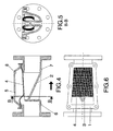
- Its body (1) contains a semi-conical deflector element (2), with its axis parallel to the longitudinal axis of the valve, there being on the upper part of said element (2) a flat open face (3) the perimeter of which has the shape of an isosceles triangle of cross section approximately equal to that of the valve passage in accordance with its nominal diameter, in order to facilitate the conveyance of fluid when the valve is fully open, since the flow passes through the triangular section.
- the vertex of the semi-cone (2) and consequently the outermost vertex of the triangular opening (3), are oriented towards the fluid intake part to the valve.
- the flexible diaphragm (4) adopts a flat shape in the zone where it is seated, adapting itself to the sides of the triangular passage section in order to achieve fluid leak-tightness when it is partially or totally shut, pressed against its seating by the fluid contained in the chamber formed by the cover (5) and the diaphragm (4).
- the opening of the valve is produced by draining the fluid from said chamber, whereby the incoming fluid pressure pushes the diaphragm (4) separating it from its seating and facilitating its discharge through the triangular passage section of the semi-conical deflector (2).
- the actuation of the valve in shutting or reducing flow shall be from back to front (upstream), starting with the higher flow rates; and the reverse (downstream) in the opening process or increasing flow.
- valve On its body the valve has orifices each of which serves for connection purposes when employing pilot valves or other devices. Said orifices are situated on the intake part (6) and discharge part (7), and also on the chamber (8). When the valve is used as an automatic regulator, said orifices are connected in an adequate manner to the regulator pilot.
Landscapes
- Engineering & Computer Science (AREA)
- General Engineering & Computer Science (AREA)
- Mechanical Engineering (AREA)
- Physics & Mathematics (AREA)
- Fluid Mechanics (AREA)
- Fluid-Driven Valves (AREA)
- Control Of Fluid Pressure (AREA)
- Lift Valve (AREA)
- Multiple-Way Valves (AREA)
- Safety Valves (AREA)
Applications Claiming Priority (3)
| Application Number | Priority Date | Filing Date | Title |
|---|---|---|---|
| ES200000544A ES2178915B1 (es) | 2000-03-07 | 2000-03-07 | Valvula hidraulica de membrana perfeccionada, para regulacion del caudal de fluidos. |
| ES200000544 | 2000-03-07 | ||
| PCT/ES2001/000087 WO2001066916A2 (es) | 2000-03-07 | 2001-03-06 | Válvula hidráulica de membrana perfeccionada, para regulación del caudal de fluidos |
Publications (2)
| Publication Number | Publication Date |
|---|---|
| EP1267109A2 true EP1267109A2 (de) | 2002-12-18 |
| EP1267109B1 EP1267109B1 (de) | 2003-11-19 |
Family
ID=8492599
Family Applications (1)
| Application Number | Title | Priority Date | Filing Date |
|---|---|---|---|
| EP01915428A Expired - Lifetime EP1267109B1 (de) | 2000-03-07 | 2001-03-06 | Hydraulisches membranventil zur regulierung des durchflusses |
Country Status (11)
| Country | Link |
|---|---|
| US (1) | US6616120B2 (de) |
| EP (1) | EP1267109B1 (de) |
| AT (1) | ATE254735T1 (de) |
| AU (2) | AU4252501A (de) |
| DE (1) | DE60101267D1 (de) |
| ES (2) | ES2178915B1 (de) |
| IL (1) | IL151651A (de) |
| PT (1) | PT1267109E (de) |
| TR (1) | TR200302273T4 (de) |
| WO (1) | WO2001066916A2 (de) |
| ZA (1) | ZA200207876B (de) |
Cited By (1)
| Publication number | Priority date | Publication date | Assignee | Title |
|---|---|---|---|---|
| GB2462640A (en) * | 2008-08-14 | 2010-02-17 | Kenneth O Hara | Gas flow regulator |
Families Citing this family (12)
| Publication number | Priority date | Publication date | Assignee | Title |
|---|---|---|---|---|
| US6637476B2 (en) | 2002-04-01 | 2003-10-28 | Protedyne Corporation | Robotically manipulable sample handling tool |
| WO2004070322A2 (en) * | 2003-01-29 | 2004-08-19 | Wwetco, Llc | Apparatus and method for fluid flow control |
| US7249529B2 (en) | 2003-03-28 | 2007-07-31 | Protedyne Corporation | Robotically manipulable sample handling tool |
| MX2008011600A (es) * | 2006-03-15 | 2009-02-10 | Norgren Gmbh | Valvula de diafragma de tipo oscilante. |
| US8740177B2 (en) | 2011-07-05 | 2014-06-03 | Rain Bird Corporation | Eccentric diaphragm valve |
| US10871242B2 (en) | 2016-06-23 | 2020-12-22 | Rain Bird Corporation | Solenoid and method of manufacture |
| US10980120B2 (en) | 2017-06-15 | 2021-04-13 | Rain Bird Corporation | Compact printed circuit board |
| US11503782B2 (en) | 2018-04-11 | 2022-11-22 | Rain Bird Corporation | Smart drip irrigation emitter |
| US11721465B2 (en) | 2020-04-24 | 2023-08-08 | Rain Bird Corporation | Solenoid apparatus and methods of assembly |
| CN116056801B (zh) | 2020-08-07 | 2026-02-13 | 固瑞克明尼苏达有限公司 | 背压调节器 |
| WO2023039541A1 (en) * | 2021-09-09 | 2023-03-16 | Wayne State University | Solid state shunt valve with active outflow regulator, ventricular catheters, and other embodiments |
| CN117553151B (zh) * | 2024-01-12 | 2024-04-12 | 英侨机械制造有限公司 | 爆破片安全装置 |
Family Cites Families (14)
| Publication number | Priority date | Publication date | Assignee | Title |
|---|---|---|---|---|
| US2963266A (en) * | 1957-07-11 | 1960-12-06 | Grinnell Corp | Valve |
| US3374522A (en) * | 1965-01-22 | 1968-03-26 | Grinnell Corp | Method of making diaphragm valve bodies |
| IL52446A (en) * | 1977-07-04 | 1981-10-30 | Barmad Kibbutz Evron | Diaphragm valves |
| US4232851A (en) * | 1979-02-06 | 1980-11-11 | Textron Inc. | Fluid control valve and liner therefor |
| DE3742207A1 (de) * | 1987-12-12 | 1989-06-22 | Lang Apparatebau Gmbh | Rueckflussverhinderer, insbesondere zum einbau in trinkwasserleitungen |
| IL92851A (en) * | 1989-12-22 | 1996-10-31 | Evron Kibbutz Bernad | Diaphragm control valve |
| US5127430A (en) * | 1990-02-01 | 1992-07-07 | Industrial Ceramics Engineering | Ceramic weir for valve body |
| DE4106071A1 (de) * | 1991-02-27 | 1992-09-03 | Morlock Gmbh | Membranbaueinheit |
| DE4204386C2 (de) * | 1992-02-14 | 1994-01-20 | Honeywell Braukmann Gmbh | Systemtrenner |
| US5327937A (en) * | 1993-01-06 | 1994-07-12 | Sekisui Kagaku Kogyo Kabushiki Kaisha | Branched valve |
| US6109296A (en) * | 1993-08-06 | 2000-08-29 | Austin; Cary M. | Dribble flow valve |
| IL119963A (en) * | 1997-01-05 | 2003-02-12 | Raphael Valves Ind 1975 Ltd | Spring diaphragm for shut-off valves and regulators |
| US5909747A (en) * | 1998-04-03 | 1999-06-08 | American Meter Company | Radial flow diaphragm valve |
| DE19826610A1 (de) * | 1998-06-16 | 1999-12-23 | Bran & Luebbe | Membranpumpe und Vorrichtung zur Steuerung derselben |
-
2000
- 2000-03-07 ES ES200000544A patent/ES2178915B1/es not_active Expired - Fee Related
-
2001
- 2001-03-06 AU AU4252501A patent/AU4252501A/xx active Pending
- 2001-03-06 ES ES01915428T patent/ES2208574T3/es not_active Expired - Lifetime
- 2001-03-06 WO PCT/ES2001/000087 patent/WO2001066916A2/es not_active Ceased
- 2001-03-06 EP EP01915428A patent/EP1267109B1/de not_active Expired - Lifetime
- 2001-03-06 AT AT01915428T patent/ATE254735T1/de not_active IP Right Cessation
- 2001-03-06 PT PT01915428T patent/PT1267109E/pt unknown
- 2001-03-06 IL IL15165101A patent/IL151651A/xx not_active IP Right Cessation
- 2001-03-06 DE DE60101267T patent/DE60101267D1/de not_active Expired - Lifetime
- 2001-03-06 TR TR2003/02273T patent/TR200302273T4/xx unknown
- 2001-03-06 AU AU2001242525A patent/AU2001242525B2/en not_active Ceased
-
2002
- 2002-09-06 US US10/238,513 patent/US6616120B2/en not_active Expired - Fee Related
- 2002-10-01 ZA ZA200207876A patent/ZA200207876B/en unknown
Non-Patent Citations (1)
| Title |
|---|
| See references of WO0166916A2 * |
Cited By (1)
| Publication number | Priority date | Publication date | Assignee | Title |
|---|---|---|---|---|
| GB2462640A (en) * | 2008-08-14 | 2010-02-17 | Kenneth O Hara | Gas flow regulator |
Also Published As
| Publication number | Publication date |
|---|---|
| ZA200207876B (en) | 2003-10-01 |
| US20030075701A1 (en) | 2003-04-24 |
| ES2178915A1 (es) | 2003-01-01 |
| IL151651A0 (en) | 2003-04-10 |
| AU4252501A (en) | 2001-09-17 |
| IL151651A (en) | 2005-09-25 |
| AU2001242525B2 (en) | 2005-07-14 |
| PT1267109E (pt) | 2004-02-27 |
| EP1267109B1 (de) | 2003-11-19 |
| WO2001066916A2 (es) | 2001-09-13 |
| TR200302273T4 (tr) | 2004-03-22 |
| ES2208574T3 (es) | 2004-06-16 |
| ES2178915B1 (es) | 2004-04-16 |
| ATE254735T1 (de) | 2003-12-15 |
| US6616120B2 (en) | 2003-09-09 |
| WO2001066916A3 (es) | 2001-12-20 |
| DE60101267D1 (de) | 2003-12-24 |
Similar Documents
| Publication | Publication Date | Title |
|---|---|---|
| EP1267109B1 (de) | Hydraulisches membranventil zur regulierung des durchflusses | |
| EP0257811B1 (de) | Durchflussventil | |
| US4730635A (en) | Valve and method | |
| AU642936B2 (en) | Diaphragm control valve | |
| US7059578B2 (en) | Diaphragm and hydraulically-operated valve using same | |
| EP0247716A2 (de) | Sicherheits-Druckentlastungssystem für Regel- oder Entlüftungsventile | |
| JP2001099344A (ja) | 背圧制御弁 | |
| US20090120511A1 (en) | Standpipe direct float valve | |
| GB2231126A (en) | Diaphragm valve | |
| CN216200561U (zh) | 一种中压空气节流阀 | |
| CN111442122B (zh) | 一种船用双重密封防浪阀 | |
| CN222798275U (zh) | 一种膜片式蒸汽减压阀 | |
| CN209511144U (zh) | 一种直接作用式减压阀结构 | |
| CN212839597U (zh) | 一种船用空气减压阀 | |
| KR100459333B1 (ko) | 유체 압력차에 의해 제어되는 정수위밸브 | |
| CN213298946U (zh) | 一种精密减压阀 | |
| JP3341198B2 (ja) | パイロット式背圧弁 | |
| CN217153001U (zh) | 一种带有并联通道的比例阀 | |
| CN218493918U (zh) | 用于液压执行器上综合机能的油路块 | |
| CN220134713U (zh) | 一种新型可调压差阀 | |
| CN115355325B (zh) | 三点平衡轴流式调压器 | |
| EP1510738B1 (de) | Metallmembranventil | |
| KR100414161B1 (ko) | 차압작동식 자동제어용 밸브 | |
| CN211398683U (zh) | 恒压导阀 | |
| JP3509284B2 (ja) | 減圧弁 |
Legal Events
| Date | Code | Title | Description |
|---|---|---|---|
| PUAI | Public reference made under article 153(3) epc to a published international application that has entered the european phase |
Free format text: ORIGINAL CODE: 0009012 |
|
| 17P | Request for examination filed |
Effective date: 20021004 |
|
| AK | Designated contracting states |
Kind code of ref document: A2 Designated state(s): AT BE CH CY DE DK ES FI FR GB GR IE IT LI LU MC NL PT SE TR |
|
| AX | Request for extension of the european patent |
Free format text: AL;LT;LV;MK;RO;SI |
|
| GRAH | Despatch of communication of intention to grant a patent |
Free format text: ORIGINAL CODE: EPIDOS IGRA |
|
| GRAS | Grant fee paid |
Free format text: ORIGINAL CODE: EPIDOSNIGR3 |
|
| GRAA | (expected) grant |
Free format text: ORIGINAL CODE: 0009210 |
|
| AK | Designated contracting states |
Kind code of ref document: B1 Designated state(s): AT BE CH CY DE DK ES FI FR GB GR IE IT LI LU MC NL PT SE TR |
|
| PG25 | Lapsed in a contracting state [announced via postgrant information from national office to epo] |
Ref country code: BE Free format text: LAPSE BECAUSE OF FAILURE TO SUBMIT A TRANSLATION OF THE DESCRIPTION OR TO PAY THE FEE WITHIN THE PRESCRIBED TIME-LIMIT Effective date: 20031119 Ref country code: LI Free format text: LAPSE BECAUSE OF FAILURE TO SUBMIT A TRANSLATION OF THE DESCRIPTION OR TO PAY THE FEE WITHIN THE PRESCRIBED TIME-LIMIT Effective date: 20031119 Ref country code: AT Free format text: LAPSE BECAUSE OF FAILURE TO SUBMIT A TRANSLATION OF THE DESCRIPTION OR TO PAY THE FEE WITHIN THE PRESCRIBED TIME-LIMIT Effective date: 20031119 Ref country code: FI Free format text: LAPSE BECAUSE OF FAILURE TO SUBMIT A TRANSLATION OF THE DESCRIPTION OR TO PAY THE FEE WITHIN THE PRESCRIBED TIME-LIMIT Effective date: 20031119 Ref country code: CH Free format text: LAPSE BECAUSE OF FAILURE TO SUBMIT A TRANSLATION OF THE DESCRIPTION OR TO PAY THE FEE WITHIN THE PRESCRIBED TIME-LIMIT Effective date: 20031119 Ref country code: CY Free format text: LAPSE BECAUSE OF FAILURE TO SUBMIT A TRANSLATION OF THE DESCRIPTION OR TO PAY THE FEE WITHIN THE PRESCRIBED TIME-LIMIT Effective date: 20031119 |
|
| REG | Reference to a national code |
Ref country code: GB Ref legal event code: FG4D |
|
| REG | Reference to a national code |
Ref country code: CH Ref legal event code: EP |
|
| REF | Corresponds to: |
Ref document number: 60101267 Country of ref document: DE Date of ref document: 20031224 Kind code of ref document: P |
|
| REG | Reference to a national code |
Ref country code: IE Ref legal event code: FG4D |
|
| REG | Reference to a national code |
Ref country code: GR Ref legal event code: EP Ref document number: 20030405246 Country of ref document: GR |
|
| PG25 | Lapsed in a contracting state [announced via postgrant information from national office to epo] |
Ref country code: DK Free format text: LAPSE BECAUSE OF FAILURE TO SUBMIT A TRANSLATION OF THE DESCRIPTION OR TO PAY THE FEE WITHIN THE PRESCRIBED TIME-LIMIT Effective date: 20040219 Ref country code: SE Free format text: LAPSE BECAUSE OF FAILURE TO SUBMIT A TRANSLATION OF THE DESCRIPTION OR TO PAY THE FEE WITHIN THE PRESCRIBED TIME-LIMIT Effective date: 20040219 |
|
| PG25 | Lapsed in a contracting state [announced via postgrant information from national office to epo] |
Ref country code: DE Free format text: LAPSE BECAUSE OF FAILURE TO SUBMIT A TRANSLATION OF THE DESCRIPTION OR TO PAY THE FEE WITHIN THE PRESCRIBED TIME-LIMIT Effective date: 20040220 |
|
| PG25 | Lapsed in a contracting state [announced via postgrant information from national office to epo] |
Ref country code: LU Free format text: LAPSE BECAUSE OF NON-PAYMENT OF DUE FEES Effective date: 20040306 |
|
| PG25 | Lapsed in a contracting state [announced via postgrant information from national office to epo] |
Ref country code: IE Free format text: LAPSE BECAUSE OF NON-PAYMENT OF DUE FEES Effective date: 20040308 |
|
| PG25 | Lapsed in a contracting state [announced via postgrant information from national office to epo] |
Ref country code: MC Free format text: LAPSE BECAUSE OF NON-PAYMENT OF DUE FEES Effective date: 20040331 |
|
| LTIE | Lt: invalidation of european patent or patent extension |
Effective date: 20031119 |
|
| REG | Reference to a national code |
Ref country code: CH Ref legal event code: PL |
|
| REG | Reference to a national code |
Ref country code: ES Ref legal event code: FG2A Ref document number: 2208574 Country of ref document: ES Kind code of ref document: T3 |
|
| ET | Fr: translation filed | ||
| PLBE | No opposition filed within time limit |
Free format text: ORIGINAL CODE: 0009261 |
|
| STAA | Information on the status of an ep patent application or granted ep patent |
Free format text: STATUS: NO OPPOSITION FILED WITHIN TIME LIMIT |
|
| 26N | No opposition filed |
Effective date: 20040820 |
|
| REG | Reference to a national code |
Ref country code: IE Ref legal event code: MM4A |
|
| PG25 | Lapsed in a contracting state [announced via postgrant information from national office to epo] |
Ref country code: GB Free format text: LAPSE BECAUSE OF NON-PAYMENT OF DUE FEES Effective date: 20050306 |
|
| PGFP | Annual fee paid to national office [announced via postgrant information from national office to epo] |
Ref country code: FR Payment date: 20050325 Year of fee payment: 5 |
|
| GBPC | Gb: european patent ceased through non-payment of renewal fee |
Effective date: 20050306 |
|
| PGFP | Annual fee paid to national office [announced via postgrant information from national office to epo] |
Ref country code: TR Payment date: 20060213 Year of fee payment: 6 |
|
| PGFP | Annual fee paid to national office [announced via postgrant information from national office to epo] |
Ref country code: PT Payment date: 20060221 Year of fee payment: 6 |
|
| PGFP | Annual fee paid to national office [announced via postgrant information from national office to epo] |
Ref country code: NL Payment date: 20060315 Year of fee payment: 6 |
|
| PGFP | Annual fee paid to national office [announced via postgrant information from national office to epo] |
Ref country code: GR Payment date: 20060331 Year of fee payment: 6 |
|
| PG25 | Lapsed in a contracting state [announced via postgrant information from national office to epo] |
Ref country code: PT Free format text: LAPSE BECAUSE OF NON-PAYMENT OF DUE FEES Effective date: 20070906 |
|
| REG | Reference to a national code |
Ref country code: PT Ref legal event code: MM4A Free format text: LAPSE DUE TO NON-PAYMENT OF FEES Effective date: 20070906 |
|
| NLV4 | Nl: lapsed or anulled due to non-payment of the annual fee |
Effective date: 20071001 |
|
| REG | Reference to a national code |
Ref country code: FR Ref legal event code: ST Effective date: 20071130 |
|
| PG25 | Lapsed in a contracting state [announced via postgrant information from national office to epo] |
Ref country code: NL Free format text: LAPSE BECAUSE OF NON-PAYMENT OF DUE FEES Effective date: 20071001 |
|
| PG25 | Lapsed in a contracting state [announced via postgrant information from national office to epo] |
Ref country code: FR Free format text: LAPSE BECAUSE OF NON-PAYMENT OF DUE FEES Effective date: 20070402 |
|
| PG25 | Lapsed in a contracting state [announced via postgrant information from national office to epo] |
Ref country code: FR Free format text: LAPSE BECAUSE OF NON-PAYMENT OF DUE FEES Effective date: 20060331 |
|
| PG25 | Lapsed in a contracting state [announced via postgrant information from national office to epo] |
Ref country code: GR Free format text: LAPSE BECAUSE OF NON-PAYMENT OF DUE FEES Effective date: 20071003 |
|
| PG25 | Lapsed in a contracting state [announced via postgrant information from national office to epo] |
Ref country code: TR Free format text: LAPSE BECAUSE OF FAILURE TO SUBMIT A TRANSLATION OF THE DESCRIPTION OR TO PAY THE FEE WITHIN THE PRESCRIBED TIME-LIMIT Effective date: 20031119 |
|
| PGFP | Annual fee paid to national office [announced via postgrant information from national office to epo] |
Ref country code: IT Payment date: 20110324 Year of fee payment: 11 |
|
| PGFP | Annual fee paid to national office [announced via postgrant information from national office to epo] |
Ref country code: ES Payment date: 20110307 Year of fee payment: 11 |
|
| PG25 | Lapsed in a contracting state [announced via postgrant information from national office to epo] |
Ref country code: IT Free format text: LAPSE BECAUSE OF NON-PAYMENT OF DUE FEES Effective date: 20120306 |
|
| REG | Reference to a national code |
Ref country code: ES Ref legal event code: FD2A Effective date: 20130710 |
|
| PG25 | Lapsed in a contracting state [announced via postgrant information from national office to epo] |
Ref country code: ES Free format text: LAPSE BECAUSE OF NON-PAYMENT OF DUE FEES Effective date: 20120307 |