EP1267149A2 - Capteur de charge utilisant un résonateur à quartz - Google Patents
Capteur de charge utilisant un résonateur à quartz Download PDFInfo
- Publication number
- EP1267149A2 EP1267149A2 EP02253940A EP02253940A EP1267149A2 EP 1267149 A2 EP1267149 A2 EP 1267149A2 EP 02253940 A EP02253940 A EP 02253940A EP 02253940 A EP02253940 A EP 02253940A EP 1267149 A2 EP1267149 A2 EP 1267149A2
- Authority
- EP
- European Patent Office
- Prior art keywords
- quartz resonator
- load
- oscillation
- load sensor
- quartz
- Prior art date
- Legal status (The legal status is an assumption and is not a legal conclusion. Google has not performed a legal analysis and makes no representation as to the accuracy of the status listed.)
- Withdrawn
Links
Images


Classifications
-
- G—PHYSICS
- G01—MEASURING; TESTING
- G01G—WEIGHING
- G01G3/00—Weighing apparatus characterised by the use of elastically-deformable members, e.g. spring balances
- G01G3/12—Weighing apparatus characterised by the use of elastically-deformable members, e.g. spring balances wherein the weighing element is in the form of a solid body stressed by pressure or tension during weighing
- G01G3/13—Weighing apparatus characterised by the use of elastically-deformable members, e.g. spring balances wherein the weighing element is in the form of a solid body stressed by pressure or tension during weighing having piezoelectric or piezoresistive properties
Definitions
- the present invention relates to a load sensor with use of a quartz resonator for measuring a load, more specifically to a load sensor capable of minimizing oscillation energy leakage of a thickness shear oscillation of a quartz resonator toward the outside as much as possible.
- Strain-gauge load cells have been widely used as a load sensor for electronic weighing scales. However, in these years, with rapid advance in electronic measurement technologies, load sensors which are more accurate than the strain-gauge load cells have been developed. Of these load sensors, different types such as a tuning fork type, a string oscillation type, a gyroscope type, and the like have already been put into practical use.
- an oscillation-type load sensor with use of a quartz resonator takes advantage of such phenomenon that an oscillation frequency of an AT-cut platy quartz piece which is under thickness shear oscillation excited by exciting means varies in proportion to a force applied to the quartz piece in parallel with a platy face thereof.
- the quartz resonator has advantages such as less temperature dependency, oscillation with stable frequency, and inexpensiveness. For this reason, the use of the quartz resonator makes it possible to attain a load sensor which is higher in accuracy and lower in cost as compared to load sensors described above such as the tuning fork type, the string oscillation type, the gyroscope type and the like.
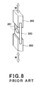
- Fig 8 is a perspective view showing a constitution of basic parts of a conventional load sensor with use of a quartz resonator.
- a platy quartz resonator 300 is a quartz piece which oscillates in a thickness shear oscillation mode in the length direction. Electrodes 301, 301 are respectively affixed to both faces of the quartz resonator 300, and these electrodes 301, 301 are connected to an oscillation circuit (not shown) which oscillates in proportion to the oscillating frequency of the quartz resonator 300.
- grooves which are rectangular in cross-section are formed at end portions of supporting bodies 302, 302 which support the quartz resonator 300 throughout the plate widths. And, the quartz resonator 300 is retained by the supporting bodies 302, 302 in the thickness direction through respectively fitting both of the end portions of the quartz resonator 300 into the grooves.
- the oscillation frequency of the quartz resonator 300 changes in proportion to the load W, and then the oscillation frequency of the above-described oscillation circuit changes in proportion to the change.
- the load W is measured by detecting this change in the oscillation frequency.
- both of the end portions of the quartz resonator 300 and the grooves formed at the ends of the supporting bodies 302, 302 may be fixed to each other by use of adhesive or the like. In these cases, since the quartz resonator 300 remains fixed even if the supporting bodies 302, 302 move away from each other, a load W applied in the pulling direction can also be measured.
- the present invention has been developed under these circumferences, and an object thereof is to provide a load sensor with use of a quartz resonator which has high Q of the quartz resonator and is capable of performing measurements with a high degree of accuracy, which are achieved by supporting the quartz resonator so as not to restrain the thickness shear oscillation and so as to minimize the oscillation transmitted to the supporting bodies.
- a load sensor with use of a quartz resonator comprises: a long-plate shaped quartz resonator; supporting bodies for respectively supporting both lengthwise end portions of the quartz resonator; and exciting means for exciting a thickness shear oscillation at a center portion of the quartz resonator in the length direction, wherein middle portions whose thickness is smaller than that of the center portion are respectively provided between the center portion and both of the end portions and a load is measured based on change in an oscillation frequency of the thickness shear oscillation of the center portion of the quartz resonator generated in proportion to the load acted thereon through the supporting bodies.
- the thickness of the middle portion is smaller than that of the center portion, even if the thickness shear oscillation is excited by the exciting means at the center portion of the quartz resonator, the oscillation is not easily transmitted to both of the end portions. For this reason, the oscillation transmitted to the supporting bodies supporting both of these end portions can be reduced. Therefore, it is possible to restrain the surrounding mechanism from resonating and to realize more accurate measurements, compared to the conventional load sensor.
- the central portion can be configured to form symmetrical grooves with respect to a thicknesswise central position of the quartz resonator.
- the thickness shear oscillation of the quartz resonator is generated, both surfaces thereof move most but not the thicknesswise central position of the quartz resonator. Therefore, the formation of the symmetrical grooves with respect to the thicknesswise central position will set relatively most moving potions free, thereby reducing oscillation energy loss of the quartz resonator and thus increasing Q as an oscillator, as compared to the conventional load sensor.
- a load sensor with use of a quartz resonator comprises: a flat-plate shaped quartz resonator for oscillating in a thickness shear oscillation mode and supporting bodies for supporting the quartz resonator, wherein the quartz resonator is retained between the supporting bodies which are respectively in contact with and pressing opposing end faces of the quartz resonator from the outside of the quartz resonator, the end faces are configured to minimize the areas contacting with the supporting bodies as much as possible, and a load is measured based on change in an oscillation frequency of the thickness shear oscillation of the quartz resonator generated in proportion to the load acted thereon through the supporting bodies.
- the opposing end faces of the quartz resonator are configured to minimize the areas, that the supporting bodies are in contact with and pressing, as much as possible, the transmission of the thickness shear oscillation of the quartz resonator to the supporting bodies can be minimized as much as possible. Therefore, it is possible to restrain the surrounding mechanism from resonating and to realize more accurate measurements, as compared to the conventional load sensor. What is more, the fabrication of the quartz resonator is simpler for the present invention than for the above-described invention.
- the end faces may be circular-arc shaped.
- Figs. 1A-1C are perspective views showing a quartz resonator used in a load sensor according to Embodiment 1 of the present invention.
- a long-plate shape quartz resonator 1 is an AT-cut quartz piece capable of oscillating in a thickness shear oscillation mode in a length direction of the quartz resonator 1.
- Excitation electrodes 2, 2 serving as exciting means are respectively affixed to both surfaces of a central portion 1a of the quartz resonator 1.
- the central portion 1a starts the thickness shear oscillation in the length direction of the quartz resonator 1 when an electric signal is supplied to the central portion 1a of the quartz resonator 1 through the excitation electrodes 2, 2. It should be noted that these electrodes 2, 2 are connected to an oscillation circuit described below.
- channel-shape grooves in cross-section are respectively provided in the plate width direction on both surfaces of middle portions 1c, 1c which are located between the center portion 1a and end portions 1b, 1b of the quartz resonator 1.
- These grooves are formed so as to be symmetrical with respect to a thicknesswise central position of the quartz resonator 1 by use of a well-known etching technique such as photo-etching and the like.
- the thickness of the middle portions 1c, 1c is smaller than the thickness of the central portion 1a. Because of that, even if the central portion 1a oscillates in the thickness shear oscillation mode, its oscillation is not easily transmitted to both of the end portions 1b, 1b.
- the grooves are formed so as to be symmetrical with respect to the thicknesswise central position of the quartz resonator 1, portions of the plate to be moved most when the thickness shear oscillation is generated is set free. Because of this, the thickness shear oscillation can be restrained, thereby reducing the amount of oscillation energy loss.
- the channel-shape grooves in cross-section are provided in the plate width direction on the middle portions 1c, 1c of the quartz resonator 1, as described before, these grooves are not limited to this shape and may be of any shape as far as they are formed so as to be symmetrical with respect to the thicknesswise central position of the quartz resonator 1. Therefore, the shape may be, for example, of half-circle shape in cross-section as shown in Fig. 1B or of trapezoid-shape in cross-section as shown in Fig. 1C.
- Figs. 2A and 2B are perspective views showing load sensors according to Embodiment 1 of the present invention.
- Fig 2A shows a load sensor which can measure a load only in the compressing direction of the load W
- Fig. 2B shows a load sensor which can measure a load both in the compressing and pulling directions of the load W.
- Figs. 2A and 2B show the load sensor with use of the quartz resonator 1 shown in Fig. 1C, it is needless to say that the quartz resonator shown in Fig. 1A or 1B may be used instead.
- Fig. 2A rectangular grooves in cross-section are formed at the end portions of the supporting bodies 3, 3 throughout the plate width, and the quartz resonator 1 is supported by respectively fitting both of the end portions 1b, 1b of the quartz resonator 1 into these grooves. Supporting the quartz resonator 1 in the way described above enables the measurement of a load W in its compressing direction.
- Fig. 2B grooves are formed at end portions of the supporting bodies 3, 3 throughout the plate widths, whose shape enables the grooves of the supporting bodies to fit on both of the end portions 1b, 1b of and portions of the grooves formed on both surfaces of the middle portions 1c, 1c of the quartz resonator 1.
- the quartz resonator 1 is supported by respectively fitting the grooves of the supporting bodies on both of the end portions 1b, 1b and the portions of the grooves formed on both of the surfaces of the middle portions 1c, 1c.
- the oscillation circuit 21 is connected to the excitation electrodes 2, 2. This oscillation circuit 21 oscillates in proportion to an oscillation frequency of the thickness shear oscillation of the central portion 1a of the quartz resonator 1. If a load W is applied through the supporting bodies 3, 3, the oscillation frequency of the central portion 1a should vary, and then the oscillation frequency of the oscillation circuit 21 should also vary accordingly.
- Fig. 3 is a side elevation view showing a constitution of an electronic scale with a load sensor according to the present invention.
- Fig. 4 is a perspective view showing in detail a constitution of the quartz resonator 1 and the supporting bodies 3, 3 which are used in the electronic scale.
- the electronic scale 10 is configured such that a tray 11 used to receive a load W is supported through so-called Roberval's mechanism.
- This Roberval's mechanism comprises a fixed pole 12 fixed to a base table B, a movable pole 13 for supporting the tray 11 described above, and upper and lower beams 14, 14 arranged to be parallel to each other.
- Levers 15, 15 are respectively provided at and protruded inwardly from an upper portion of the fixed pole 12 and a lower portion of the movable pole 13, and the supporting bodies 3, 3 for supporting the quartz resonator 1 are respectively attached to tip portions of the levers 15, 15.
- Half-circle shaped cutout portions are respectively provided at upper and lower portions of the beams 14, 14, and the thickness between the upper and lower cutout portions is small. Because of this, when the movable pole 13 moves downwardly due to a load W, the beams 14, 14 should be bent downwardly in proportion to the move. By controlling the extent of the bent, the parallel relation between the beams 14, 14 can be maintained.
- the quartz resonator 1 used in the electronic scale 10 is supported by the supporting bodies 3, 3 in the manner described before with reference to Fig. 2B.
- These supporting bodies 3, 3 are respectively connected to the levers 15, 15, and flexures 16, 16 are formed at the connected portions.
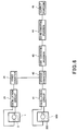
- Fig. 5 is a functional block diagram showing a constitution of the electronic scale 10.
- the oscillation circuit 21 oscillates in proportion to an inherent frequency of the thickness shear oscillation of the quartz resonator 1.
- a counter 22 counts the oscillation frequency of the oscillation circuit 21 during a predetermined period of time. It should be noted that the counter 22 counts through offsetting the oscillation frequency of the oscillation circuit 21 when zero load W is applied to the tray 11. Therefore, only varied amount responsible for the load W can be counted.
- a converting portion 23 converts the counted values from the counter 22 into weight data.
- the converting portion 23 performs such calculations through multiplications of the gravitational acceleration and a variety of proportionality factors, etc. that the converted value becomes equivalent to the weight data obtained when standard weights are placed on the tray 11.
- An output portion 24 is comprised of a liquid crystal display, a printer, or the like and displays, prints, etc. the weight data outputted by the converting portion 23.
- a quartz resonator 100 is a quartz piece which can oscillate approximately 100 times as high frequency as the quartz resonator 1 and located at such an adequate place that the influence from a load W is ignored even when the load W is applied to the tray 11.
- excitation electrodes 200, 200 are respectively affixed to central portions of both surfaces of this quartz resonator 100. And, these excitation electrodes 200, 200 are connected to an oscillation circuit 41, and the oscillation circuit 41 oscillates in proportion to an inherent frequency of the quartz resonator 100.
- a first counter 31 counts an integer cycle of an oscillation frequency of the oscillation circuit 21. And, a gate circuit (not shown) that a second counter 42 has is opened or closed according to the counted integer cycle.
- the second counter 42 counts an oscillation period of the oscillation circuit 41 while the gate circuit is open. In this case, as a load W increases, that is, as the oscillation frequency of the oscillation circuit 21 increases, the length of time that the gate circuit is open is reduced. Because of this, the counted value of the second counter 42 is inversely proportional to the value of the load W. It should be noted that, similarly to the counter 22 described before, the second counter 42 also counts through offsetting the oscillation frequency of the oscillation circuit 41 when the load W is zero.
- a first converting portion 43 calculates a reciprocal number of the period counted by the second counter 42, that is, the frequency. And, a second converting portion 44 processes the conversion from frequencies to weight data, similarly to the converting portion 23 described above. The resulting weight data are displayed or printed by an output portion 45.
- Figs. 7A and 7B are perspective views showing a constitution of a load sensor with a quartz resonator according to Embodiment 2 of the present invention.
- a quartz resonator 4 is a rectangular AT-cut quartz piece and retained between rectangular parallelepiped supporting bodies 6, 6 which are respectively in contact with and pressing end faces of one end portion and the other opposing end portion thereof from the outside. The end faces are worked on with a file so as to be circular-arc shaped in cross-section. Since the other elements are identical to those of Embodiment 1, the same or corresponding parts are denoted by the same reference numerals and as such will be not described herein.
- the end faces of the quartz resonator 4 are circular-arc shaped, the contacting areas with the supporting bodies 6, 6 are smaller as compared with the case where the end faces are flat. Because of this, when the quartz resonator 4 oscillates in the thickness shear oscillation mode, the oscillation transmitted to the supporting bodies 6, 6 can be minimized, thereby restraining the surrounding mechanism from resonating. Furthermore, since it is also possible to set relatively most moving potions free, high Q can be attained.
- a quartz resonator 7 shown in Fig. 7B is a circular AT-cut quartz piece. To form opposing end faces, end portions of this quartz resonator 7 are cut along two adequate parallel lines orthogonal to the oscillating direction of the thickness shear oscillation. The end faces thus formed are worked on so as to be circular-arc shaped similarly to the one described before. Therefore, the same effects described before can be obtained.
- the load sensor thus constructed according to Embodiment 2 of the present invention can be applied to electronic scales similarly to Embodiment 1.
Landscapes
- Physics & Mathematics (AREA)
- General Physics & Mathematics (AREA)
- Piezo-Electric Or Mechanical Vibrators, Or Delay Or Filter Circuits (AREA)
- Oscillators With Electromechanical Resonators (AREA)
Applications Claiming Priority (2)
| Application Number | Priority Date | Filing Date | Title |
|---|---|---|---|
| JP2001175327 | 2001-06-11 | ||
| JP2001175327A JP2002365123A (ja) | 2001-06-11 | 2001-06-11 | 水晶振動子を用いた荷重センサ |
Publications (2)
| Publication Number | Publication Date |
|---|---|
| EP1267149A2 true EP1267149A2 (fr) | 2002-12-18 |
| EP1267149A3 EP1267149A3 (fr) | 2003-10-22 |
Family
ID=19016488
Family Applications (1)
| Application Number | Title | Priority Date | Filing Date |
|---|---|---|---|
| EP02253940A Withdrawn EP1267149A3 (fr) | 2001-06-11 | 2002-06-06 | Capteur de charge utilisant un résonateur à quartz |
Country Status (5)
| Country | Link |
|---|---|
| US (2) | US6880407B2 (fr) |
| EP (1) | EP1267149A3 (fr) |
| JP (1) | JP2002365123A (fr) |
| CN (2) | CN1222760C (fr) |
| TW (1) | TW542905B (fr) |
Families Citing this family (19)
| Publication number | Priority date | Publication date | Assignee | Title |
|---|---|---|---|---|
| JP2002365123A (ja) * | 2001-06-11 | 2002-12-18 | Yamato Scale Co Ltd | 水晶振動子を用いた荷重センサ |
| AUPS322702A0 (en) * | 2002-06-28 | 2002-07-18 | Cochlear Limited | Cochlear implant electrode array |
| CA2442234A1 (fr) * | 2002-09-29 | 2004-03-29 | D.A.T.A. Diamond Advanced Technology Ltd. | Appareil servant a peser les petits objets |
| US7082845B2 (en) * | 2003-09-05 | 2006-08-01 | Weigh Point Incorporated | Device for leaf chain load cell |
| US20080154339A1 (en) | 2006-12-21 | 2008-06-26 | Cochlear Limited | Electrically Nonconductive Occludent For Tissue Openings |
| JP4611954B2 (ja) * | 2006-09-29 | 2011-01-12 | 日本電波工業株式会社 | 感知装置 |
| US7608986B2 (en) * | 2006-10-02 | 2009-10-27 | Seiko Epson Corporation | Quartz crystal resonator |
| US8718795B2 (en) * | 2007-03-20 | 2014-05-06 | Cochlear Limited | Securing an implanted medical device in a patient |
| US9402990B2 (en) * | 2007-03-20 | 2016-08-02 | Cochlear Limited | Securing an implanted medical device in a patient |
| WO2010096439A1 (fr) * | 2009-02-17 | 2010-08-26 | Leversense, Llc | Détecteurs résonants et leurs procédés d'utilisation pour la détermination d'analytes |
| EP2450685A4 (fr) * | 2009-06-30 | 2012-12-19 | Shinko Denshi Kk | Capteur de détection de charge |
| TWI396311B (zh) * | 2010-08-20 | 2013-05-11 | Txc Corp | Manufacturing Method of Wafer - level Packaging Structure for Through - hole Oscillator |
| TWI422080B (zh) * | 2010-08-20 | 2014-01-01 | Txc Corp | Enhanced gas - tightness of the oscillator device wafer - level package structure |
| CN102445259B (zh) * | 2010-10-14 | 2014-08-06 | 深圳市宇恒互动科技开发有限公司 | 一种重量测量方法和装置 |
| EP3467462B1 (fr) * | 2016-06-06 | 2023-09-06 | National University Corporation Nagoya University | Capteur de charge à gamme étendue utilisant un résonateur à quartz |
| JP6797764B2 (ja) * | 2017-08-09 | 2020-12-09 | 日本電波工業株式会社 | 水晶振動子およびその製造方法 |
| CN107621318B (zh) * | 2017-10-30 | 2023-07-25 | 莆田市力天量控有限公司 | 变高度等强度梁的多梁式力传感器 |
| US10840882B2 (en) * | 2018-04-24 | 2020-11-17 | Nihon Dempa Kogyo Co., Ltd. | Crystal unit and manufacturing method thereof |
| JP2019193066A (ja) * | 2018-04-24 | 2019-10-31 | 日本電波工業株式会社 | 水晶振動子 |
Family Cites Families (15)
| Publication number | Priority date | Publication date | Assignee | Title |
|---|---|---|---|---|
| US2443700A (en) * | 1948-06-22 | Electrical components | ||
| US2482730A (en) * | 1947-06-23 | 1949-09-20 | Premier Crystal Lab Inc | Piezoelectric crystal unit |
| US2505121A (en) * | 1949-03-04 | 1950-04-25 | James Knights Company | Method of finishing crystals |
| CH497691A (de) | 1968-07-24 | 1970-10-15 | Sauter Kg August | Elektromechanischer Kraft-Frequenzwandler für Waagen |
| US4067241A (en) | 1974-08-22 | 1978-01-10 | James Patrick Corbett | Improvements in or relating to oscillating crystal transducer systems |
| FR2338607A1 (fr) * | 1976-01-16 | 1977-08-12 | France Etat | Resonateur a quartz a electrodes non adherentes au cristal |
| US4175243A (en) | 1977-11-17 | 1979-11-20 | Corbett James P | Temperature compensated oscillating crystal force transducer systems |
| US4384495A (en) | 1980-11-17 | 1983-05-24 | Quartex, Inc. | Mounting system for applying forces to load-sensitive resonators |
| US4445065A (en) * | 1981-09-14 | 1984-04-24 | The Singer Company | Non-prismal beam resonator |
| JPS5850816A (ja) * | 1981-09-21 | 1983-03-25 | Tokyo Denpa Kk | 水晶振動子 |
| JPS6010122A (ja) | 1983-06-30 | 1985-01-19 | Shinko Denshi Kk | 荷重変換機構 |
| US4644804A (en) * | 1984-07-17 | 1987-02-24 | Franz Rittmeyer Ag | Quartz resonating force and pressure transducer |
| US5424598A (en) * | 1994-01-18 | 1995-06-13 | Corbett; James P. | Crystal force and pressure transducers |
| KR20010021135A (ko) * | 1999-08-05 | 2001-03-15 | 사토 히로시 | 압전공진자 및 압전공진부 |
| JP2002365123A (ja) * | 2001-06-11 | 2002-12-18 | Yamato Scale Co Ltd | 水晶振動子を用いた荷重センサ |
-
2001
- 2001-06-11 JP JP2001175327A patent/JP2002365123A/ja active Pending
-
2002
- 2002-05-16 TW TW091110305A patent/TW542905B/zh not_active IP Right Cessation
- 2002-06-05 US US10/163,858 patent/US6880407B2/en not_active Expired - Fee Related
- 2002-06-06 EP EP02253940A patent/EP1267149A3/fr not_active Withdrawn
- 2002-06-11 CN CN02124323.9A patent/CN1222760C/zh not_active Expired - Fee Related
- 2002-06-11 CN CN200510005918.6A patent/CN1677066A/zh active Pending
-
2005
- 2005-02-22 US US11/065,209 patent/US20050139016A1/en not_active Abandoned
Also Published As
| Publication number | Publication date |
|---|---|
| US20050139016A1 (en) | 2005-06-30 |
| TW542905B (en) | 2003-07-21 |
| US20030006853A1 (en) | 2003-01-09 |
| JP2002365123A (ja) | 2002-12-18 |
| US6880407B2 (en) | 2005-04-19 |
| CN1677066A (zh) | 2005-10-05 |
| CN1222760C (zh) | 2005-10-12 |
| EP1267149A3 (fr) | 2003-10-22 |
| CN1391089A (zh) | 2003-01-15 |
Similar Documents
| Publication | Publication Date | Title |
|---|---|---|
| US6880407B2 (en) | Load sensor with use of crystal resonator | |
| US4544858A (en) | Piezoelectric mechanism for converting weight into frequency | |
| US4838369A (en) | Load cell having digital output | |
| EP0161533A2 (fr) | Transducteur de température à résonance | |
| Blom et al. | Resonating silicon beam force sensor | |
| GB1600883A (en) | System and method of measuring fluid pressure force | |
| JP3676822B2 (ja) | 表面弾性波を利用する電子的重さ計量装置 | |
| US4587853A (en) | Vibration type force detector | |
| Ueda et al. | Precision force transducers using mechanical resonators | |
| JPH0579929B2 (fr) | ||
| US10788358B2 (en) | Surface acoustic wave scale that automatically updates calibration information | |
| US3885427A (en) | Electronic balance for measuring masses or forces | |
| US6448513B1 (en) | Electronic weighing apparatus utilizing surface acoustic waves | |
| US6269696B1 (en) | Temperature compensated oscillating accelerometer with force multiplier | |
| Tilmans et al. | A differential resonator design using a bossed structure for applications in mechanical sensors | |
| JP2003517585A (ja) | 表面弾性波を利用した改良された電子秤量装置 | |
| JPS6033057A (ja) | 加速度センサ | |
| JP5575129B2 (ja) | 荷重検出センサ | |
| JPS5856406B2 (ja) | 水晶トランスデュサ | |
| JPH02161323A (ja) | 質量測定器 | |
| SU873142A1 (ru) | Измеритель мощности сверхвысоких частот | |
| JPH023452B2 (fr) | ||
| Yan et al. | Development of metallic digital strain gauges | |
| Franklin Lakes | 42nd Annual Frequency Control Symposium 1988 | |
| SU662817A1 (ru) | Частотный преобразователь веса |
Legal Events
| Date | Code | Title | Description |
|---|---|---|---|
| PUAI | Public reference made under article 153(3) epc to a published international application that has entered the european phase |
Free format text: ORIGINAL CODE: 0009012 |
|
| AK | Designated contracting states |
Kind code of ref document: A2 Designated state(s): AT BE CH CY DE DK ES FI FR GB GR IE IT LI LU MC NL PT SE TR |
|
| AX | Request for extension of the european patent |
Free format text: AL;LT;LV;MK;RO;SI |
|
| PUAL | Search report despatched |
Free format text: ORIGINAL CODE: 0009013 |
|
| RIC1 | Information provided on ipc code assigned before grant |
Ipc: 7G 01L 1/16 B Ipc: 7G 01G 3/13 A |
|
| AK | Designated contracting states |
Kind code of ref document: A3 Designated state(s): AT BE CH CY DE DK ES FI FR GB GR IE IT LI LU MC NL PT SE TR |
|
| AX | Request for extension of the european patent |
Extension state: AL LT LV MK RO SI |
|
| 17P | Request for examination filed |
Effective date: 20040305 |
|
| AKX | Designation fees paid |
Designated state(s): DE FR GB NL |
|
| 17Q | First examination report despatched |
Effective date: 20040924 |
|
| GRAP | Despatch of communication of intention to grant a patent |
Free format text: ORIGINAL CODE: EPIDOSNIGR1 |
|
| RIC1 | Information provided on ipc code assigned before grant |
Ipc: G01G 3/13 20060101AFI20060411BHEP |
|
| STAA | Information on the status of an ep patent application or granted ep patent |
Free format text: STATUS: THE APPLICATION IS DEEMED TO BE WITHDRAWN |
|
| 18D | Application deemed to be withdrawn |
Effective date: 20061031 |