EP1267330A1 - Réduction de la dispersion dans les signaux vocaux codés - Google Patents
Réduction de la dispersion dans les signaux vocaux codés Download PDFInfo
- Publication number
- EP1267330A1 EP1267330A1 EP02013526A EP02013526A EP1267330A1 EP 1267330 A1 EP1267330 A1 EP 1267330A1 EP 02013526 A EP02013526 A EP 02013526A EP 02013526 A EP02013526 A EP 02013526A EP 1267330 A1 EP1267330 A1 EP 1267330A1
- Authority
- EP
- European Patent Office
- Prior art keywords
- sample values
- output
- sparseness
- sequence
- signal
- Prior art date
- Legal status (The legal status is an assumption and is not a legal conclusion. Google has not performed a legal analysis and makes no representation as to the accuracy of the status listed.)
- Granted
Links
- 238000001228 spectrum Methods 0.000 claims description 18
- 230000003044 adaptive effect Effects 0.000 claims description 12
- 238000001914 filtration Methods 0.000 claims description 11
- 230000015572 biosynthetic process Effects 0.000 claims description 7
- 230000001413 cellular effect Effects 0.000 claims description 7
- 238000003786 synthesis reaction Methods 0.000 claims description 7
- 230000007423 decrease Effects 0.000 claims description 3
- 238000000034 method Methods 0.000 description 18
- 238000004891 communication Methods 0.000 description 10
- 238000012986 modification Methods 0.000 description 7
- 230000004048 modification Effects 0.000 description 7
- 230000015556 catabolic process Effects 0.000 description 4
- 238000006731 degradation reaction Methods 0.000 description 4
- 230000006835 compression Effects 0.000 description 3
- 238000007906 compression Methods 0.000 description 3
- 230000000694 effects Effects 0.000 description 3
- 230000005284 excitation Effects 0.000 description 3
- 238000010586 diagram Methods 0.000 description 2
- 239000011159 matrix material Substances 0.000 description 2
- 239000000654 additive Substances 0.000 description 1
- 230000000996 additive effect Effects 0.000 description 1
- 238000004040 coloring Methods 0.000 description 1
- 230000003247 decreasing effect Effects 0.000 description 1
- 238000007689 inspection Methods 0.000 description 1
- 230000003595 spectral effect Effects 0.000 description 1
Images


Classifications
-
- G—PHYSICS
- G10—MUSICAL INSTRUMENTS; ACOUSTICS
- G10L—SPEECH ANALYSIS TECHNIQUES OR SPEECH SYNTHESIS; SPEECH RECOGNITION; SPEECH OR VOICE PROCESSING TECHNIQUES; SPEECH OR AUDIO CODING OR DECODING
- G10L19/00—Speech or audio signals analysis-synthesis techniques for redundancy reduction, e.g. in vocoders; Coding or decoding of speech or audio signals, using source filter models or psychoacoustic analysis
- G10L19/04—Speech or audio signals analysis-synthesis techniques for redundancy reduction, e.g. in vocoders; Coding or decoding of speech or audio signals, using source filter models or psychoacoustic analysis using predictive techniques
- G10L19/16—Vocoder architecture
- G10L19/18—Vocoders using multiple modes
-
- G—PHYSICS
- G10—MUSICAL INSTRUMENTS; ACOUSTICS
- G10L—SPEECH ANALYSIS TECHNIQUES OR SPEECH SYNTHESIS; SPEECH RECOGNITION; SPEECH OR VOICE PROCESSING TECHNIQUES; SPEECH OR AUDIO CODING OR DECODING
- G10L19/00—Speech or audio signals analysis-synthesis techniques for redundancy reduction, e.g. in vocoders; Coding or decoding of speech or audio signals, using source filter models or psychoacoustic analysis
- G10L19/002—Dynamic bit allocation
Definitions
- the invention relates generally to speech coding and, more particularly, to the problem of sparseness in coded speech signals.
- Speech coding is an important part of modern digital communications systems, for example, wireless radio communications systems such as digital cellular telecommunications systems. To achieve the high capacity required by such systems both today and in the future, it is imperative to provide efficient compression of speech signals while also providing high quality speech signals. In this connection, when the bit rate of a speech coder is decreased, for example to provide additional communication channel capacity for other communications signals, it is desirable to obtain a graceful degradation of speech quality without introducing annoying artefacts.
- the present invention provides an anti-sparseness operator for reducing the sparseness in a coded speech signal, or any digital signal, wherein sparseness is disadvantageous.
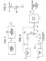
- FIGURE 1 illustrates an example of an anti-sparseness operator according to the present invention.
- the anti-sparseness operator ASO of FIGURE 1 receives at input A thereof a sparse, digital signal received from a source 11.
- the anti-sparseness operator ASO operates on the sparse signal A and provides at an output thereof a digital signal B which is less sparse than the input signal A.
- FIGURE 2 illustrates various example locations where the anti-sparseness operator ASO of FIGURE 1 can be applied in a Code Excited Linear Predictive (CELP) speech encoder provided in a transmitter for use in a wireless communication system, or in a CELP speech decoder provided in a receiver of a wireless communication system.
- the anti-sparseness operator ASO can be provided at the output of the fixed (e.g., algebraic) codebook 21, and/or at any of the locations designated by reference numerals 201-206.
- the anti-sparseness operator ASO of FIGURE 1 would receive at its input A the sparse signal and provide at its output B a less sparse signal.
- the CELP speech encoder/decoder structure shown in FIGURE 2 includes several examples of the sparse signal source of FIGURE 1.
- FIGURE 2 illustrates the conventional feedback path to the adaptive codebook as conventionally provided in CELP speech encoders/decoders. If the anti-sparseness operator ASO is provided where shown in FIGURE 2 and/or at any of locations 201-204, then the anti-sparseness operator(s) will affect the coded excitation signal reconstructed by the decoder at the output of summing circuit 210. If applied at locations 205 and/or 206, the anti-sparseness operator(s) will have no effect on the coded excitation signal output from summing circuit 210.
- FIGURE 2B illustrates an example CELP decoder including a further summing circuit 25 which receives the outputs of codebooks 21 and 23, and provides the feedback signal to the adaptive codebook 23. If the anti-sparseness operator ASO is provided where shown in FIGURE 2B, and/or at locations 220 and 240, then such anti-sparseness operator(s) will not affect the feedback signal to the adaptive codebook 23.
- FIGURE 2A illustrates a transceiver whose receiver (RCVR) includes the CELP decoder structure of FIGURE 2 (or FIGURE 2B) and whose transmitter (XMTR) includes the CELP encoder structure of FIGURE 2.
- FIGURE 2A illustrates that the transmitter receives as input an acoustical signal and provides as output to the communications channel reconstruction information from which a receiver can reconstruct the acoustical signal.
- the receiver receives as input from the communications channel reconstruction information, and provides a reconstructed acoustical signal as an output.
- the illustrated transceiver and communications channel could be, for example, a transceiver in a cellular telephone and the air interface of a cellular telephone network, respectively.
- FIGURE 3 illustrates one example implementation of the anti-sparseness operator ASO of FIGURE 1.
- a noise-like signal m(n) is added to the sparse signal as received at A.
- FIGURE 4 illustrates one example of how the signal m(n) can be produced.
- a noise signal with a Gaussian distribution N(0,1) is filtered by a suitable high pass and spectral colouring filter to produce the noise-like signal m(n).
- the signal m(n) can be applied to the summing circuit 31 with a suitable gain factor via multiplier 33.
- the gain factor of FIGURE 3 can be a fixed gain factor.
- the gain factor of FIGURE 3 can also be a function of the gain conventionally applied to the output of adaptive codebook 23 (or a similar parameter describing the amount of periodicity).
- the FIGURE 3 gain would be 0 if the adaptive codebook gain exceeds a predetermined threshold, and linearly increasing as the adaptive codebook gain decreases from the threshold.
- the FIGURE 3 gain can also be analogously implemented as a function of the gain conventionally applied to the output of the fixed codebook 21 of FIGURE 2.
- the FIGURE 3 gain can also be based on power-spectrum matching of the signal m(n) to the target signal used in the conventional search method, in which case the gain needs to be encoded and transmitted to the receiver.
- the addition of a noise-like signal can be performed in the frequency domain in order to obtain the benefit of advanced frequency domain analysis.
- FIGURE 5 illustrates another example implementation of the ASO of FIGURE 2.
- the arrangement of FIGURE 5 can be characterized as an anti-sparseness filter designed to reduce sparseness in the digital signal received from the source 11 of FIGURE 1.
- the anti-sparseness filter of FIGURE 6 includes a convolver section 63 that performs a convolution of the coded signal received from the fixed (e.g. algebraic) codebook 21 with an impulse response (at 65) associated with an all-pass filter.
- the operation of one example of the FIGURE 6 anti-sparseness filter is illustrated in FIGURES 7-11.
- FIGURE 10 illustrates an example of an entry from the codebook 21 of FIGURE 2 having only two non-zero samples out of a total of forty samples. This sparseness characteristic will be reduced if the number (density) of non-zero samples can be increased.
- One way to increase the number of non-zero samples is to apply the codebook entry of FIGURE 10 to a filter having a suitable characteristic to disperse the energy throughout the block of forty samples.
- FIGURES 7 and 8 respectively illustrate the magnitude and phase (in radians) characteristics of an all-pass filter which is operable to appropriately disperse the energy throughout the forty samples of the FIGURE 10 codebook entry.
- the filter of FIGURES 7 and 8 alters the phase spectrum in the high frequency area between 2 and 4 kHz, while altering the low frequency areas below 2 kHz only very marginally.
- the magnitude spectrum remains essentially unaltered by the filter of FIGURES 7 and 8.
- Example FIGURE 9 illustrates graphically the impulse response of the all-pass filter defined by FIGURES 7 and 8.
- the anti-sparseness filter of FIGURE 6 produces a convolution of the FIGURE 9 impulse response on the FIGURE 10 block of samples. Because the codebook entries are provided from the codebook as blocks of forty samples, the convolution operation is performed in blockwise fashion. Each sample in FIGURE 10 will produce 40 intermediate multiplication results in the convolution operation. Taking the sample at position 7 in FIGURE 10 as an example, the first 34 multiplication results are assigned to positions 7-40 of the FIGURE 11 result block, and the remaining 6 multiplication results are "wrapped around" according to a circular convolution operation such that they are assigned to positions 1-6 of the result block.
- the 40 intermediate multiplication results produced by each of the remaining FIGURE 10 samples are assigned to positions in the FIGURE 11 result block in analogous fashion, and sample 1 of course needs no wrap around.
- the 40 intermediate multiplication results assigned thereto are summed together, and that sum represents the convolution result for that position.
- FIGURES 10 and 11 It is clear from inspection of FIGURES 10 and 11 that the circular convolution operation alters the Fourier spectrum of the FIGURE 10 block so that the energy is dispersed throughout the block, thereby dramatically increasing the number (or density) of non-zero samples in the block, and correspondingly reducing the amount of sparseness.
- the effects of performing the circular convolution on a block-by-block basis can be smoothed out by the synthesis filter 211 of FIGURE 2.
- FIGURES 12-16 illustrate another example of the operation of an anti-sparseness filter of the type shown generally in FIGURE 6.
- the all-pass filter of FIGURES 12 and 13 alters the phase spectrum between 3 and 4 kHz without substantially altering the phase spectrum below 3 kHz.
- the impulse response of the filter is shown in FIGURE 14. Referencing the result block of FIGURE 16, and noting that FIGURE 15 illustrates the same block of samples as FIGURE 10, it is clear that the anti-sparseness operation illustrated in FIGURES 12-16 does not disperse the energy as much as shown in FIGURE 11.
- FIGURES 12-16 define an anti-sparseness filter which modifies the codebook entry less than the filter defined by FIGURES 7-11. Accordingly, the filters of FIGURES 7-11 and FIGURES 12-16 define respectively different levels of anti-sparseness filtering.
- a low adaptive codebook gain value indicates that the adaptive codebook component of the reconstructed excitation signal (output from adder circuit 210) will be relatively small, thus giving rise to the possibility of a relatively large contribution from the fixed (e.g. algebraic) codebook 21. Because of the aforementioned sparseness of the fixed codebook entries, it would be advantageous to select the anti-sparseness filter of FIGURES 7-11 rather than that of FIGURES 12-16 because the filter of FIGURES 7-11 provides a greater modification of the sample block than does the filter of FIGURES 12-16. With larger values of adaptive codebook gain, the fixed codebook contribution is relatively less, so the filter of FIGURES 12-16 which provides less anti-sparseness modification could be used.
- the present invention thus provides the capability of using the local characteristics of a given speech segment to determine whether and how much to modify the sparseness characteristic associated with that segment.
- the convolution performed in the FIGURE 6 anti-sparseness filter can also be linear convolution, which provides smoother operation because blockwise processing effects are avoided.
- blockwise processing is described in the above examples, such blockwise processing is not required to practice the invention, but rather is merely a characteristic of the conventional CELP speech encoder/decoder structure shown in the examples.
- a closed-loop version of the method can be used.
- the encoder takes the anti-sparseness modification into account during search of the codebooks. This will give improved performance at the price of increased complexity.
- the (circular or linear) convolution operation can be implemented by multiplying the filtering matrix constructed from the conventional impulse response of the search filter by a matrix which defines the anti-sparseness filter (using either linear or circular convolution).
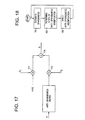
- FIGURE 17 illustrates another example of the anti-sparseness operator ASO of FIGURE 1.
- an anti-sparseness filter of the type illustrated in FIGURE 5 receives input signal A, and the output of the anti-sparseness filter is multiplied at 170 by a gain factor g 2 .
- the noise-like signal m(n) from FIGURES 3 and 4 is multiplied at 172 by a gain factor g 1 , and the outputs of the g 1 and g 2 multipliers 170 and 172 are added together at 174 to produce output signal B.
- the gain factors g 1 and g 2 can be determined, for example, as follows.
- the gain g 1 can first be determined in one of the ways described above with respect to the gain of FIGURE 3, and then the gain factor g 2 can be determined as a function of gain factor g 1 .
- gain factor g 2 can vary inversely with gain factor g 1 .
- the gain factor g 2 can be determined in the same manner as the gain of FIGURE 3, and then the gain factor g 1 can be determined as a function of gain factor g 2 , for example g 1 can vary inversely with g 2 .
- FIGURE 18 illustrates an exemplary method of providing anti-sparseness modification according to the invention.
- the level of sparseness of the coded speech signal is estimated. This can be done off-line or adaptively during speech processing. For example, in algebraic codebooks and multi-pulse codebooks the samples may be close to each other or far apart, resulting in varying sparseness; whereas in a regular pulse codebook, the distance between samples is fixed, so the sparseness is constant.
- a suitable level of anti-sparseness modification is determined. This step can also be performed off-line or adaptively during speech processing as described above. As another example of adaptively determining the anti-sparseness level, the impulse response (see FIGURES 6, 9 and 14) can be changed from block to block.
- the selected level of anti-sparseness modification is applied to the signal.
- FIGURES 1-18 can be readily implemented using, for example, a suitably programmed digital signal processor or other data processor, and can alternatively be implemented using, for example, such suitably programmed digital signal processor or other data processor in combination with additional external circuitry connected thereto.
- an apparatus for reducing sparseness in an input digital signal may have the following elements.
- a cellular telephone may be adapted for executing the method in accordance with at least one of 18) - 27).
- a cellular telephone may comprise the apparatus in accordance with at least one of the 1) - 10).
Landscapes
- Engineering & Computer Science (AREA)
- Computational Linguistics (AREA)
- Signal Processing (AREA)
- Health & Medical Sciences (AREA)
- Audiology, Speech & Language Pathology (AREA)
- Human Computer Interaction (AREA)
- Physics & Mathematics (AREA)
- Acoustics & Sound (AREA)
- Multimedia (AREA)
- Compression, Expansion, Code Conversion, And Decoders (AREA)
Applications Claiming Priority (7)
| Application Number | Priority Date | Filing Date | Title |
|---|---|---|---|
| US5775297P | 1997-09-02 | 1997-09-02 | |
| US57752P | 1997-09-02 | ||
| US34590 | 1998-03-04 | ||
| US09/034,590 US6058359A (en) | 1998-03-04 | 1998-03-04 | Speech coding including soft adaptability feature |
| US110989 | 1998-07-07 | ||
| US09/110,989 US6029125A (en) | 1997-09-02 | 1998-07-07 | Reducing sparseness in coded speech signals |
| EP98940752A EP1008141B1 (fr) | 1997-09-02 | 1998-08-25 | Reduction de la dispersion dans les signaux vocaux codes |
Related Parent Applications (2)
| Application Number | Title | Priority Date | Filing Date |
|---|---|---|---|
| EP98940752.3 Division | 1998-08-25 | ||
| EP98940752A Division EP1008141B1 (fr) | 1997-09-02 | 1998-08-25 | Reduction de la dispersion dans les signaux vocaux codes |
Publications (2)
| Publication Number | Publication Date |
|---|---|
| EP1267330A1 true EP1267330A1 (fr) | 2002-12-18 |
| EP1267330B1 EP1267330B1 (fr) | 2005-01-19 |
Family
ID=27443789
Family Applications (1)
| Application Number | Title | Priority Date | Filing Date |
|---|---|---|---|
| EP02013526A Expired - Lifetime EP1267330B1 (fr) | 1997-09-02 | 1998-08-25 | Réduction de la dispersion dans les signaux vocaux codés |
Country Status (1)
| Country | Link |
|---|---|
| EP (1) | EP1267330B1 (fr) |
Citations (5)
| Publication number | Priority date | Publication date | Assignee | Title |
|---|---|---|---|---|
| WO1991013432A1 (fr) * | 1990-02-23 | 1991-09-05 | Universite De Sherbrooke | Manuel de codage dynamique pour une articulation efficace, avec codage base sur des codes algebriques |
| JPH05158497A (ja) * | 1991-12-06 | 1993-06-25 | Fujitsu Ltd | 音声伝送方式 |
| EP0709827A2 (fr) * | 1994-10-28 | 1996-05-01 | Mitsubishi Denki Kabushiki Kaisha | Dispositif et méthode de codage et décodage de la parole et dispositif pour extraire une caractéristique de phase et d'amplitude |
| WO1996018185A1 (fr) * | 1994-12-05 | 1996-06-13 | Motorola Inc. | Procede et dispositif de caracterisation et de reconstitution de signaux d'excitation vocale |
| US5806037A (en) * | 1994-03-29 | 1998-09-08 | Yamaha Corporation | Voice synthesis system utilizing a transfer function |
-
1998
- 1998-08-25 EP EP02013526A patent/EP1267330B1/fr not_active Expired - Lifetime
Patent Citations (5)
| Publication number | Priority date | Publication date | Assignee | Title |
|---|---|---|---|---|
| WO1991013432A1 (fr) * | 1990-02-23 | 1991-09-05 | Universite De Sherbrooke | Manuel de codage dynamique pour une articulation efficace, avec codage base sur des codes algebriques |
| JPH05158497A (ja) * | 1991-12-06 | 1993-06-25 | Fujitsu Ltd | 音声伝送方式 |
| US5806037A (en) * | 1994-03-29 | 1998-09-08 | Yamaha Corporation | Voice synthesis system utilizing a transfer function |
| EP0709827A2 (fr) * | 1994-10-28 | 1996-05-01 | Mitsubishi Denki Kabushiki Kaisha | Dispositif et méthode de codage et décodage de la parole et dispositif pour extraire une caractéristique de phase et d'amplitude |
| WO1996018185A1 (fr) * | 1994-12-05 | 1996-06-13 | Motorola Inc. | Procede et dispositif de caracterisation et de reconstitution de signaux d'excitation vocale |
Non-Patent Citations (2)
| Title |
|---|
| HAGEN ET AL: "Removal of sparse-excitation artifacts in CELP", INTERNATIONAL CONFERENCE ON ACOUSTICS, SPEECH, AND SIGNAL PROCESSING, XX, XX, vol. 1, 12 May 1998 (1998-05-12), pages 145 - 148, XP002083369 * |
| PATENT ABSTRACTS OF JAPAN vol. 017, no. 557 (P - 1626) 7 October 1993 (1993-10-07) * |
Also Published As
| Publication number | Publication date |
|---|---|
| EP1267330B1 (fr) | 2005-01-19 |
Similar Documents
| Publication | Publication Date | Title |
|---|---|---|
| US6029125A (en) | Reducing sparseness in coded speech signals | |
| RU2239239C2 (ru) | Снижение разреженности в кодированных речевых сигналах | |
| US6334105B1 (en) | Multimode speech encoder and decoder apparatuses | |
| AU752229B2 (en) | Perceptual weighting device and method for efficient coding of wideband signals | |
| EP0763818B1 (fr) | Procédé et filtre pour accentuer des formants | |
| FI95086C (fi) | Menetelmä puhesignaalin tehokkaaksi koodaamiseksi | |
| DE60012760T2 (de) | Multimodaler sprachkodierer | |
| NZ536237A (en) | Method and device for pitch enhancement of decoded speech | |
| Cox et al. | New directions in subband coding | |
| US6301556B1 (en) | Reducing sparseness in coded speech signals | |
| US6205423B1 (en) | Method for coding speech containing noise-like speech periods and/or having background noise | |
| EP1267330B1 (fr) | Réduction de la dispersion dans les signaux vocaux codés | |
| HK1051082B (en) | Reducing sparseness in coded speech signals | |
| KR100718487B1 (ko) | 디지털 음성 코더들에서의 고조파 잡음 가중 | |
| RU2388069C2 (ru) | Снижение разреженности в кодированных речевых сигналах | |
| MXPA00001837A (en) | Reducing sparseness in coded speech signals | |
| EP0984433A2 (fr) | Suppression de bruit dans une unité de communication vocale et méthode d'opération | |
| MXPA96002142A (en) | Speech classification with voice / no voice for use in decodification of speech during decorated by quad |
Legal Events
| Date | Code | Title | Description |
|---|---|---|---|
| PUAI | Public reference made under article 153(3) epc to a published international application that has entered the european phase |
Free format text: ORIGINAL CODE: 0009012 |
|
| AC | Divisional application: reference to earlier application |
Ref document number: 1008141 Country of ref document: EP |
|
| AK | Designated contracting states |
Kind code of ref document: A1 Designated state(s): DE FR GB IT |
|
| 17P | Request for examination filed |
Effective date: 20030327 |
|
| AKX | Designation fees paid |
Designated state(s): DE FR GB IT |
|
| RAP1 | Party data changed (applicant data changed or rights of an application transferred) |
Owner name: TELEFONAKTIEBOLAGET LM ERICSSON (PUBL) |
|
| GRAP | Despatch of communication of intention to grant a patent |
Free format text: ORIGINAL CODE: EPIDOSNIGR1 |
|
| GRAS | Grant fee paid |
Free format text: ORIGINAL CODE: EPIDOSNIGR3 |
|
| GRAA | (expected) grant |
Free format text: ORIGINAL CODE: 0009210 |
|
| AC | Divisional application: reference to earlier application |
Ref document number: 1008141 Country of ref document: EP Kind code of ref document: P |
|
| AK | Designated contracting states |
Kind code of ref document: B1 Designated state(s): DE FR GB IT |
|
| REG | Reference to a national code |
Ref country code: GB Ref legal event code: FG4D |
|
| REF | Corresponds to: |
Ref document number: 69828709 Country of ref document: DE Date of ref document: 20050224 Kind code of ref document: P |
|
| REG | Reference to a national code |
Ref country code: HK Ref legal event code: GR Ref document number: 1051082 Country of ref document: HK |
|
| PLBE | No opposition filed within time limit |
Free format text: ORIGINAL CODE: 0009261 |
|
| STAA | Information on the status of an ep patent application or granted ep patent |
Free format text: STATUS: NO OPPOSITION FILED WITHIN TIME LIMIT |
|
| ET | Fr: translation filed | ||
| 26N | No opposition filed |
Effective date: 20051020 |
|
| REG | Reference to a national code |
Ref country code: FR Ref legal event code: PLFP Year of fee payment: 19 |
|
| REG | Reference to a national code |
Ref country code: FR Ref legal event code: PLFP Year of fee payment: 20 |
|
| PGFP | Annual fee paid to national office [announced via postgrant information from national office to epo] |
Ref country code: FR Payment date: 20170825 Year of fee payment: 20 Ref country code: DE Payment date: 20170829 Year of fee payment: 20 Ref country code: IT Payment date: 20170823 Year of fee payment: 20 Ref country code: GB Payment date: 20170829 Year of fee payment: 20 |
|
| REG | Reference to a national code |
Ref country code: DE Ref legal event code: R071 Ref document number: 69828709 Country of ref document: DE |
|
| REG | Reference to a national code |
Ref country code: GB Ref legal event code: PE20 Expiry date: 20180824 |
|
| PG25 | Lapsed in a contracting state [announced via postgrant information from national office to epo] |
Ref country code: GB Free format text: LAPSE BECAUSE OF EXPIRATION OF PROTECTION Effective date: 20180824 |