EP1268272B1 - Gestaltung eines holmes in k-form für eine geklebte flügelstruktur - Google Patents
Gestaltung eines holmes in k-form für eine geklebte flügelstruktur Download PDFInfo
- Publication number
- EP1268272B1 EP1268272B1 EP01923140A EP01923140A EP1268272B1 EP 1268272 B1 EP1268272 B1 EP 1268272B1 EP 01923140 A EP01923140 A EP 01923140A EP 01923140 A EP01923140 A EP 01923140A EP 1268272 B1 EP1268272 B1 EP 1268272B1
- Authority
- EP
- European Patent Office
- Prior art keywords
- rib
- shaped spar
- intrusions
- spar
- shaped
- Prior art date
- Legal status (The legal status is an assumption and is not a legal conclusion. Google has not performed a legal analysis and makes no representation as to the accuracy of the status listed.)
- Expired - Lifetime
Links
- 238000010276 construction Methods 0.000 title description 6
- 238000000034 method Methods 0.000 claims description 7
- 238000004519 manufacturing process Methods 0.000 description 4
- 238000009434 installation Methods 0.000 description 2
- 238000007796 conventional method Methods 0.000 description 1
- 238000012986 modification Methods 0.000 description 1
- 230000004048 modification Effects 0.000 description 1
Images



Classifications
-
- B—PERFORMING OPERATIONS; TRANSPORTING
- B64—AIRCRAFT; AVIATION; COSMONAUTICS
- B64C—AEROPLANES; HELICOPTERS
- B64C3/00—Wings
- B64C3/26—Construction, shape, or attachment of separate skins, e.g. panels
Definitions
- the present invention relates to aircraft wing construction.
- the present invention relates to a method and apparatus for a bonded wing construction.
- the present invention has significant advantages, including: (1) only about 5% mechanical assembly; (2) less complex assembly; (3) a reduction in part counts, detail fabrication, assembly fastener installation, and associated assembly recurring costs; (4) a reduction in the complexity of assembly tool design and non-recurring tool procurement costs; and (5) reduction in skin manufacturing costs and cycle time.
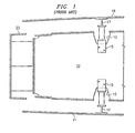
- a rib 11 includes channels 13 into which are mechanically installed angle clips 15. Angle clips 15 are mechanically coupled to I-beams 17 carried by an upper stiffened skin 19 and a ;lower stiffened skin 21.
- a C-shaped spar 23 is coupled to rib 11 and/or upper and lower skins 19 and 21. This is a typical mechanical assembly which requires a relatively large number of parts and which requires a complex assembly process.
- a rib 31 includes a plurality of generally rhombus shaped intrusions 33.
- An upper stiffened skin 35 includes a plurality (only one shown) of generally correspondingly rhombus shaped protrusions 37 that are aligned with rib intrusions 33 on the upper surface of rib 31.
- a lower stiffened skin 39 includes a plurality (only one shown) of generally correspondingly rhombus shaped protrusions 41 that are aligned with rib intrusions 33 on the lower surface of rib 31. It should be understood that the geometric shape of the protrusions can vary widely from application to application.
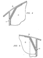
- a K-shaped spar, or K-spar, 51 is configured to conform to the end of rib 31.
- K-spar 51 is also wedge shaped in the vertical direction, having a protruding ridge 57 which mates with an intruding channel 59 in one or more ribs 31.
- Upper skin 35 includes a triangular protrusion 53.
- lower skin 39 includes a triangular shaped protrusion 55.
- K-spar 51 includes an upper triangular intrusion 61 and a lower triangular intrusion 63. It should be understood that upper and lower triangular intrusions 61 and 63 may be of other shapes.
- Skin 35 includes a tab portion 65, and skin 39 includes a tab portion 67.
- K-spar 51 includes corresponding upper and lower tab portions 69 and 71.
- protrusions 37 on upper skin 35 and protrusions 41 on lower skin 39 interlockingly mate with intrusions 33 in rib 31; protrusions 53 on upper skin 35 and protrusions 55 on lower skin 39 interlockingly mate with upper intrusions 61 and lower intrusions 63, respectively on K-spar 51; and tab portions 65 and 67 mate with tab portions 69 and 71, respectively.
- protruding ridges 57 interlockingly mate with channels 61. This configuration provides large surface areas for which to bond these component parts together and create a stiff structure. This can be done with only about 5% mechanical assembly, as opposed to the 100% mechanical assembly associated with the
- the present invention has significant advantages, including: (1) only about 5% mechanical assembly; (2) less complex assembly; (3) a reduction in part counts, detail fabrication, assembly fastener installation, and associated assembly recurring costs; (4) a reduction in the complexity of assembly tool design and non-recurring tool procurement costs; and (5) reduction in skin manufacturing costs and cycle time.
Landscapes
- Engineering & Computer Science (AREA)
- Mechanical Engineering (AREA)
- Aviation & Aerospace Engineering (AREA)
- Lining Or Joining Of Plastics Or The Like (AREA)
- Laminated Bodies (AREA)
- Standing Axle, Rod, Or Tube Structures Coupled By Welding, Adhesion, Or Deposition (AREA)
Claims (9)
- Struktur für ein Flugzeug, umfassend :eine Rippe (31) mit einer ersten und einer zweiten Oberfläche an gegenüberliegenden Seiten der Rippe, und mindestens einer Endfläche, die die erste und die zweite der Oberflächen miteinander verbindet, wobei die erste und die zweite Oberfläche jede mindestens eine Eindrückung (33) darin aufweisen ;einen mit der Rippenendfläche verbundenen K-förmigen Holm (51), wobei der K-förmige Holm eine erste (61) beziehungsweise eine zweite (63) Eindrückung benachbart zu der ersten und der zweiten Rippenfläche aufweist ;ein mit der ersten Rippenfläche verbundenes erstes Außenhautelement (35), wobei das erste Außenhautelement einen ersten Vorsprung (53) in Nähe eines Endes davon aufweist, der dazu eingerichtet ist, in die erste Eindrückung (61) des K-förmigen Holms zu passen ; und mindestens einen zusätzlichen Vorsprung (37), der dazu eingerichtet ist, in die erste Oberflächeneindrückung (33) der Rippe zu passen ; undein mit der zweiten Rippenfläche verbundenes zweites Außenhautelement (39), wobei das zweite Außenhautelement einen ersten Vorsprung (55) in Nähe eines Endes davon aufweist, der dazu eingerichtet ist, in die zweite Eindrückung (63) des K-förmigen Holms zu passen ; und mindestens einen zusätzlichen Vorsprung (41), der dazu eingerichtet ist, in die zweite Oberflächeneindrückung (33) der Rippe zu passen.
- Struktur von Anspruch 1, weiter umfassend :mindestens eine Endeindrückung (59) in der Rippenendfläche ; undentsprechend mindestens einen Vorsprung (57) an dem K-förmigen Holm (51), wobei der Vorsprung des K-förmigen Holms dazu eingerichtet ist, in die Rippenendflächeneindrückung zu passen.
- Struktur von Anspruch 2, wobei die Rippenendflächeneindrückung (59) einen dreieckigen Querschnitt hat und der Vorsprung (57) des K-förmigen Holms einen passenden dreieckigen Querschnitt hat.
- Struktur von Anspruch 1, wobei die erste und die zweite Eindrückung (61, 63) des K-förmigen Holms jede einen dreieckigen Querschnitt haben und wobei die ersten Vorsprünge (53, 55) des ersten und des zweiten Außenhautelements jeder einen dreieckigen Querschnitt haben, der zu der ersten beziehungsweise zweiten Eindrückung des K-förmigen Holms passt.
- Struktur von Anspruch 1, wobei der erste und der zweite der gegenüberliegenden Rippenflächeneindrückungen (33) einen rautenförmigen Querschnitt haben und die erste und die zweite der Außenhautelementvorsprünge (37, 41) jeweils einen rautenförmigen Querschnitt haben, der zu der ersten und der zweiten der gegenüberliegenden Rippenflächeneindrückungen passt.
- Struktur von Anspruch 1, wobei die Rippe eine zweite Endfläche gegenüber der Endfläche hat und weiter umfasst :einen zweiten, mit der zweiten Endfläche der Rippe verbundenen K-förmigen Holm, wobei der zweite K-förmige Holm eine erste und eine zweite Eindrückung benachbart zu der ersten bzw. der zweiten Rippenfläche aufweist ;wobei das erste und das zweite der Außenhautelemente zusätzlich zweite Vorsprünge in Nähe jeweiliger zweiter Enden davon haben, wobei solche zweiten Vorsprünge dazu eingerichtet sind, in die erste beziehungsweise die zweite Eindrückung des zweiten K-förmigen Holms zu passen.
- Struktur von Anspruch 1, wobei der K-förmige Holm mindestens einen Vorsprung umfasst, der sich von der Rippenendfläche weg und annähernd koplanar mit der ersten Fläche der Rippe erstreckt, und wobei das erste Außenhautelement einen vorspringenden Teil an dem mit dem Vorsprung des K-förmigen Holms verbundenen Ende aufweist.
- Verfahren zum Zusammenbau einer Struktur für ein Flugzeug, umfassend folgende Schritte :Bereitstellen einer Rippe (31) mit einer ersten und einer zweiten Fläche auf gegenüberliegenden Seiten der Rippe, und mindestens einer Endfläche, wobei die erste und die zweite Fläche jede mindestens eine Eindrückung (33) darin aufweisen ;Verbinden eines K-förmigen Holms (51) mit der Rippenendfläche, wobei der K-förmige Holm eine erste und eine zweite Eindrückung (61, 63) darin aufweist, benachbart zu der ersten und der zweiten Rippenfläche ; undVerbinden eines ersten und eines zweiten Außenhautelements (35, 39) mit der ersten beziehungsweise zweiten Rippenfläche, wobei das erste und das zweite der Außenhautelemente jeweils Vorsprünge (53, 57, 37, 41) aufweisen, die den Rippenflächeneindrückungen (33) beziehungsweise der ersten und der zweiten Eindrückung (61, 63) des K-förmigen Holms entsprechen und dazu eingerichtet sind, mit diesen ineinanderzugreifen.
- Verfahren von Anspruch 8, wobei die Schritte des Verbindens das Miteinanderverbinden der Rippe (31), des K-förmigen Holms (51) und der Außenhautelemente (35, 39) mit einem Klebematerial umfassen.
Applications Claiming Priority (3)
| Application Number | Priority Date | Filing Date | Title |
|---|---|---|---|
| US19461000P | 2000-04-05 | 2000-04-05 | |
| US194610P | 2000-04-05 | ||
| PCT/US2001/010991 WO2001076939A2 (en) | 2000-04-05 | 2001-04-05 | K-spar configuration for bonded wing construction |
Publications (3)
| Publication Number | Publication Date |
|---|---|
| EP1268272A2 EP1268272A2 (de) | 2003-01-02 |
| EP1268272A4 EP1268272A4 (de) | 2006-05-31 |
| EP1268272B1 true EP1268272B1 (de) | 2007-05-30 |
Family
ID=22718241
Family Applications (1)
| Application Number | Title | Priority Date | Filing Date |
|---|---|---|---|
| EP01923140A Expired - Lifetime EP1268272B1 (de) | 2000-04-05 | 2001-04-05 | Gestaltung eines holmes in k-form für eine geklebte flügelstruktur |
Country Status (6)
| Country | Link |
|---|---|
| US (1) | US6739553B2 (de) |
| EP (1) | EP1268272B1 (de) |
| AU (1) | AU2001249862A1 (de) |
| CA (1) | CA2402848C (de) |
| DE (2) | DE60128664T2 (de) |
| WO (1) | WO2001076939A2 (de) |
Families Citing this family (9)
| Publication number | Priority date | Publication date | Assignee | Title |
|---|---|---|---|---|
| AT410656B (de) * | 2001-10-24 | 2003-06-25 | Fischer Adv Components Gmbh | Trag- bzw. führungsvorrichtung für flugzeugkomponenten |
| GB0611875D0 (en) * | 2006-06-15 | 2006-07-26 | Airbus Uk Ltd | A stringer for an aircraft wing and a method of forming thereof |
| US7686251B2 (en) * | 2006-12-13 | 2010-03-30 | The Boeing Company | Rib support for wing panels |
| US7721995B2 (en) * | 2006-12-13 | 2010-05-25 | The Boeing Company | Rib support for wing panels |
| ES2346834B1 (es) * | 2007-04-30 | 2011-08-17 | Airbus Operations, S.L. | Estructura de costilla para cajones de torsion de un ala o de un estabilizador de una aeronave. |
| CN103434638A (zh) * | 2013-09-16 | 2013-12-11 | 哈尔滨工业大学 | 复合材料机翼中梁与加强肋的混合连接方法 |
| US9517833B2 (en) * | 2015-04-28 | 2016-12-13 | The Boeing Company | Apparatuses and methods for manufacturing a structure |
| GB2575102A (en) * | 2018-06-29 | 2020-01-01 | Airbus Operations Ltd | Duct stringer with bulkhead |
| GB2617556A (en) | 2022-04-08 | 2023-10-18 | Airbus Operations Ltd | Wing-box structure |
Family Cites Families (23)
| Publication number | Priority date | Publication date | Assignee | Title |
|---|---|---|---|---|
| DE361286C (de) * | 1922-01-21 | 1922-10-16 | Hugh Lwan Gramatzki | Mikrometer |
| US1822940A (en) * | 1928-08-20 | 1931-09-15 | American Avigation Corp | Wing structure for airplanes |
| US1900067A (en) * | 1928-09-25 | 1933-03-07 | Messerschmitt Willy | Spar for airplanes |
| US1880478A (en) * | 1929-05-03 | 1932-10-04 | Budd Edward G Mfg Co | Airplane structure |
| US1956823A (en) * | 1929-06-13 | 1934-05-01 | Cairns Dev Company | Wing structure |
| US1908757A (en) * | 1929-08-06 | 1933-05-16 | Curtiss Aeroplane & Motor Co | Aeronautical truss and method of forming the same |
| US1919088A (en) * | 1931-03-25 | 1933-07-18 | Aviation Louis Breguet Sa | Wing structure for flying machines |
| US1866961A (en) * | 1931-07-02 | 1932-07-12 | Giuseppe M Bellanca | Wing structure |
| US1976480A (en) * | 1931-10-29 | 1934-10-09 | Curtiss Aeroplane & Motor Co | Aerofoil |
| US1988079A (en) * | 1932-05-27 | 1935-01-15 | Curtiss Wright Airplane Compan | Airplane wing |
| US2233969A (en) * | 1938-12-30 | 1941-03-04 | Bell Aircraft Corp | Pressed wing rib |
| US2693922A (en) | 1952-01-19 | 1954-11-09 | Northrop Aircraft Inc | Leading edge structure for airfoil |
| FR2292623A1 (fr) * | 1974-11-26 | 1976-06-25 | Aerospatiale | Procede pour la realisation de structures composites resistantes, notamment pour aerodynes et structures ainsi obtenues |
| US4095322A (en) * | 1976-08-30 | 1978-06-20 | The Boeing Company | Method of fabricating a composite aerodynamic rotorblade assembly |
| US4356616A (en) * | 1980-02-25 | 1982-11-02 | Rockwell International Corporation | Method of making rib structures for an airfoil |
| US4565595A (en) | 1981-09-30 | 1986-01-21 | The Boeing Company | Method of making composite aircraft wing |
| WO1987001431A1 (en) * | 1984-02-28 | 1987-03-12 | Offshore Marine Pty. Ltd. | Structural member |
| US4892435A (en) * | 1989-02-06 | 1990-01-09 | Grumman Aerospace Corporation | Interlocking structural members employing transverse locking double interfitting wedge |
| US5330092A (en) | 1991-12-17 | 1994-07-19 | The Boeing Company | Multiple density sandwich structures and method of fabrication |
| DE19529476C2 (de) | 1995-08-11 | 2000-08-10 | Deutsch Zentr Luft & Raumfahrt | Flügel mit schubsteifen Flügelschalen aus Faserverbundwerkstoffen für Luftfahrzeuge |
| US5848765A (en) | 1996-06-20 | 1998-12-15 | The Boeing Company | Reduced amplitude corrugated web spar |
| JP2000043796A (ja) * | 1998-07-30 | 2000-02-15 | Japan Aircraft Development Corp | 複合材の翼形構造およびその成形方法 |
| FR2803821B1 (fr) * | 2000-01-17 | 2002-04-05 | Dassault Aviat | Bec de voilure d'aeronef equipe d'un dispositif d'antigivrage, voilure equipee d'un tel bec, et aeronef equipe d'une telle voilure |
-
2001
- 2001-04-05 EP EP01923140A patent/EP1268272B1/de not_active Expired - Lifetime
- 2001-04-05 DE DE60128664T patent/DE60128664T2/de not_active Expired - Lifetime
- 2001-04-05 CA CA002402848A patent/CA2402848C/en not_active Expired - Lifetime
- 2001-04-05 WO PCT/US2001/010991 patent/WO2001076939A2/en not_active Ceased
- 2001-04-05 DE DE1268272T patent/DE1268272T1/de active Pending
- 2001-04-05 AU AU2001249862A patent/AU2001249862A1/en not_active Abandoned
- 2001-04-05 US US10/221,642 patent/US6739553B2/en not_active Expired - Lifetime
Also Published As
| Publication number | Publication date |
|---|---|
| US20040035981A1 (en) | 2004-02-26 |
| US6739553B2 (en) | 2004-05-25 |
| WO2001076939A3 (en) | 2002-05-23 |
| EP1268272A2 (de) | 2003-01-02 |
| DE60128664T2 (de) | 2008-01-31 |
| DE60128664D1 (de) | 2007-07-12 |
| DE1268272T1 (de) | 2003-06-26 |
| EP1268272A4 (de) | 2006-05-31 |
| WO2001076939A2 (en) | 2001-10-18 |
| CA2402848A1 (en) | 2001-10-18 |
| CA2402848C (en) | 2009-06-16 |
| AU2001249862A1 (en) | 2001-10-23 |
Similar Documents
| Publication | Publication Date | Title |
|---|---|---|
| EP1268272B1 (de) | Gestaltung eines holmes in k-form für eine geklebte flügelstruktur | |
| RU2418205C2 (ru) | Соединение панелей и способ монтажа соединения панелей | |
| US6158915A (en) | Attachment member for board materials | |
| US6945727B2 (en) | Apparatuses and methods for joining structural members, such as composite structural members | |
| KR102525530B1 (ko) | 항공기, 항공기 날개들 및 연관된 전단 타이들 | |
| US4892435A (en) | Interlocking structural members employing transverse locking double interfitting wedge | |
| EP0976650A3 (de) | Verbundwerkstoff-Flugzeugstrukturen und ihre Herstellung | |
| EP3075653B1 (de) | Verbundrippe für ein flugzeug | |
| EP2589531A2 (de) | Aus einem verbundmaterial hergestellte interne struktur für flugzeuge | |
| GB2047334A (en) | Sealing slide fastener stringer | |
| US7500640B2 (en) | Hollow assembly structure and fabrication method therefor | |
| JPH06191489A (ja) | 繊維複合材料から成るシェル構造体 | |
| GB2312483A (en) | Joint assembly | |
| EP2281745B1 (de) | Kopplungssystem zur verwendung zwischen verkleidungen und strukturträgerelemente dafür | |
| CN1246829A (zh) | 用于连接塑料件和金属件的夹紧装置 | |
| US11319051B2 (en) | Stiffened composite ribs | |
| US7850387B2 (en) | System for reducing stress concentrations in lap joints | |
| US4904109A (en) | Interlocking structural members employing transverse locking wedges | |
| JPH0886304A (ja) | リブ付きブラインドリベット | |
| US5050820A (en) | Interlocking structural members employing triple interfitting wedge | |
| AU755595B2 (en) | Ore screening panel system | |
| EP4089008A1 (de) | Lösbare verbindung mit geringem widerstand für aerodynamische flächen | |
| EP3779213B1 (de) | Verbindungsanordnung | |
| JP2502919Y2 (ja) | 鬼 瓦 | |
| KR0141142B1 (ko) | 경비행기의 수평 미익 |
Legal Events
| Date | Code | Title | Description |
|---|---|---|---|
| PUAI | Public reference made under article 153(3) epc to a published international application that has entered the european phase |
Free format text: ORIGINAL CODE: 0009012 |
|
| 17P | Request for examination filed |
Effective date: 20020920 |
|
| AK | Designated contracting states |
Kind code of ref document: A2 Designated state(s): AT BE CH CY DE DK ES FI FR GB GR IE IT LI LU MC NL PT SE TR |
|
| AX | Request for extension of the european patent |
Free format text: AL;LT;LV;MK;RO;SI |
|
| EL | Fr: translation of claims filed | ||
| DET | De: translation of patent claims | ||
| RBV | Designated contracting states (corrected) |
Designated state(s): DE FR GB IT |
|
| A4 | Supplementary search report drawn up and despatched |
Effective date: 20060420 |
|
| RIC1 | Information provided on ipc code assigned before grant |
Ipc: B64C 3/18 20060101AFI20060412BHEP |
|
| GRAP | Despatch of communication of intention to grant a patent |
Free format text: ORIGINAL CODE: EPIDOSNIGR1 |
|
| GRAS | Grant fee paid |
Free format text: ORIGINAL CODE: EPIDOSNIGR3 |
|
| GRAA | (expected) grant |
Free format text: ORIGINAL CODE: 0009210 |
|
| AK | Designated contracting states |
Kind code of ref document: B1 Designated state(s): DE FR GB IT |
|
| REG | Reference to a national code |
Ref country code: GB Ref legal event code: FG4D |
|
| REF | Corresponds to: |
Ref document number: 60128664 Country of ref document: DE Date of ref document: 20070712 Kind code of ref document: P |
|
| ET | Fr: translation filed | ||
| PLBE | No opposition filed within time limit |
Free format text: ORIGINAL CODE: 0009261 |
|
| STAA | Information on the status of an ep patent application or granted ep patent |
Free format text: STATUS: NO OPPOSITION FILED WITHIN TIME LIMIT |
|
| 26N | No opposition filed |
Effective date: 20080303 |
|
| REG | Reference to a national code |
Ref country code: FR Ref legal event code: PLFP Year of fee payment: 16 |
|
| REG | Reference to a national code |
Ref country code: FR Ref legal event code: PLFP Year of fee payment: 17 |
|
| REG | Reference to a national code |
Ref country code: FR Ref legal event code: PLFP Year of fee payment: 18 |
|
| PGFP | Annual fee paid to national office [announced via postgrant information from national office to epo] |
Ref country code: IT Payment date: 20190423 Year of fee payment: 19 Ref country code: DE Payment date: 20190429 Year of fee payment: 19 |
|
| PGFP | Annual fee paid to national office [announced via postgrant information from national office to epo] |
Ref country code: FR Payment date: 20190425 Year of fee payment: 19 |
|
| PGFP | Annual fee paid to national office [announced via postgrant information from national office to epo] |
Ref country code: GB Payment date: 20190429 Year of fee payment: 19 |
|
| REG | Reference to a national code |
Ref country code: DE Ref legal event code: R119 Ref document number: 60128664 Country of ref document: DE |
|
| PG25 | Lapsed in a contracting state [announced via postgrant information from national office to epo] |
Ref country code: FR Free format text: LAPSE BECAUSE OF NON-PAYMENT OF DUE FEES Effective date: 20200430 Ref country code: DE Free format text: LAPSE BECAUSE OF NON-PAYMENT OF DUE FEES Effective date: 20201103 |
|
| GBPC | Gb: european patent ceased through non-payment of renewal fee |
Effective date: 20200405 |
|
| PG25 | Lapsed in a contracting state [announced via postgrant information from national office to epo] |
Ref country code: GB Free format text: LAPSE BECAUSE OF NON-PAYMENT OF DUE FEES Effective date: 20200405 |
|
| PG25 | Lapsed in a contracting state [announced via postgrant information from national office to epo] |
Ref country code: IT Free format text: LAPSE BECAUSE OF NON-PAYMENT OF DUE FEES Effective date: 20200405 |