EP1268908B1 - Dispositif de formation de motifs - Google Patents
Dispositif de formation de motifs Download PDFInfo
- Publication number
- EP1268908B1 EP1268908B1 EP01923005A EP01923005A EP1268908B1 EP 1268908 B1 EP1268908 B1 EP 1268908B1 EP 01923005 A EP01923005 A EP 01923005A EP 01923005 A EP01923005 A EP 01923005A EP 1268908 B1 EP1268908 B1 EP 1268908B1
- Authority
- EP
- European Patent Office
- Prior art keywords
- dye
- mounting plate
- substrate
- manifold
- control
- Prior art date
- Legal status (The legal status is an assumption and is not a legal conclusion. Google has not performed a legal analysis and makes no representation as to the accuracy of the status listed.)
- Expired - Lifetime
Links
- 238000000059 patterning Methods 0.000 title claims abstract description 20
- 239000012530 fluid Substances 0.000 claims abstract description 27
- 239000000758 substrate Substances 0.000 claims description 23
- 239000007788 liquid Substances 0.000 abstract description 6
- 239000000975 dye Substances 0.000 description 78
- 239000000463 material Substances 0.000 description 8
- 239000004753 textile Substances 0.000 description 7
- 230000015572 biosynthetic process Effects 0.000 description 6
- 239000003086 colorant Substances 0.000 description 6
- 238000000034 method Methods 0.000 description 4
- 238000003491 array Methods 0.000 description 3
- 238000002156 mixing Methods 0.000 description 3
- 238000013459 approach Methods 0.000 description 2
- 238000006243 chemical reaction Methods 0.000 description 2
- 239000004744 fabric Substances 0.000 description 2
- 230000007246 mechanism Effects 0.000 description 2
- 230000004913 activation Effects 0.000 description 1
- 239000000853 adhesive Substances 0.000 description 1
- 230000001070 adhesive effect Effects 0.000 description 1
- 238000004040 coloring Methods 0.000 description 1
- 238000006073 displacement reaction Methods 0.000 description 1
- 238000004043 dyeing Methods 0.000 description 1
- 238000010304 firing Methods 0.000 description 1
- 238000011065 in-situ storage Methods 0.000 description 1
- 239000002184 metal Substances 0.000 description 1
- 239000007787 solid Substances 0.000 description 1
Images


Classifications
-
- D—TEXTILES; PAPER
- D06—TREATMENT OF TEXTILES OR THE LIKE; LAUNDERING; FLEXIBLE MATERIALS NOT OTHERWISE PROVIDED FOR
- D06B—TREATING TEXTILE MATERIALS USING LIQUIDS, GASES OR VAPOURS
- D06B11/00—Treatment of selected parts of textile materials, e.g. partial dyeing
- D06B11/0056—Treatment of selected parts of textile materials, e.g. partial dyeing of fabrics
- D06B11/0059—Treatment of selected parts of textile materials, e.g. partial dyeing of fabrics by spraying
Definitions
- This disclosure relates to an improved system for mounting and aligning, in a manner that is both accurate and precise, an array oftubes used for delivering relatively small quantities of air or other fluids in various applications, as, for example, in patterning systems in which a stream of a patterning fluid such as a liquid dye is deflected from a trajectory by the impingement of a stream of a control fluid such as air.
- a patterning fluid such as a liquid dye
- a variety of commercially viable methods and associated machines for coloring or patterning webs of materials are known. Among such methods is that in which a plurality of individual dye jets are arranged in a linear array, referred to as a gun bar, that is positioned across the path of a moving web of a substrate to be patterned, most commonly a textile substrate such as fabric or carpeting.
- U.S. Patent No. 3,939,675 discloses an apparatus for dyeing and printing materials employing dye applicator gun bars to direct a plurality of streams of dye onto the moving material in a predetermined pattern.
- the dye jets are positioned so that each individual dye stream from a respective dye jet is directed continuously onto the surface of the moving substrate web, unless the stream is deflected or otherwise interrupted by a stream of control fluid from a corresponding array of control fluid tubes that are positioned in close proximity to the emerging stream of dye from the dye jets.
- the individual streams of control fluid in this case, air, are formed by a linear army of control tubes, preferably positioned in accordance with the teachings herein across the path of a moving web of textile material, so that each control tube in the array is precisely aligned with a corresponding stream of dye that is directed onto the surface of the moving web by the dye jet associated with that control tube.
- pressurized air (or other control fluid) is sent through one or more of the control tubes comprising the control tube array. Because of the alignment achievable using the teachings herein, air streams emerging from any of the tubes comprising the control tube array will precisely intersect the trajectory of the dye stream and interrupt or deflect the dye stream sufficiently to prevent the stream from contacting the surface of the web for a time period corresponding to the duration of the activation of the 'control stream.
- Each dye jet array or gun bar is supplied with dye of a different color, and, by careful choice of the colors used to supply each array, and by using various techniques for mixing or blending the various colors on the substrate, a wide variety of different colors can be generated. By actuating individually each of the dye jets in each of the various arrays over different time intervals (thereby applying different quantities of dye in various locations on the substrate), patterns of considerable complexity may be generated.
- the individual actuation of the dye jets is controlled by an electronic computer, which converts a desired pattern into a series of firing commands for the control streams associated with each of the individual dye jets in each of the arrays, taking into account the speed of the web as it passes under each of the arrays, the inter-array spacing, the requirements for in situ blending of various dyes to achieve the desired color as required by the patterning instructions, and other factors.
- a control tube adapted for carrying bursts of a pressurized control fluid is uniquely associated with each of the individual dye jets.
- control tubes are oriented to provide a conduit for a stream of control fluid that is in a transverse orientation to the stream of dye emerging from the dye jet.
- the stream of control fluid - which may be air or other fluid - intersects the stream of dye early in its trajectory and thereby diverts the dye stream and prevents the stream from contacting the substrate.
- a manifold can be cast or machined with a series of apertures through which the pressurized control fluid may pass.
- control stream tubes have frequently been aligned using an alignment plate having a series of precisely machined V-shaped notches, with the centerline (i.e., the axis of symmetry) of each notch corresponding to the axis of the dye stream to be controlled.
- Each tube in the array is positioned within a respective V-notch, which has been sized to accommodate the diameter of the tube in a way that prevents the tube from being completely contained within the notch (i.e., the depth of the notch that will accommodate the tube is smaller than the diameter of the tube).
- a separate confinement plate is secured to the alignment plate, forcing the tubes into the notches. In theory, this should serve to maintain the tubes in solid contact with the sides of the respective notches, thereby centering them within the notches and, presumably, aligning the tubes in a uniformly spaced, linear array.
- U.S. Patent No. 4,309,881 discloses an apparatus for the application of liquids to moving materials, wherein air outlets of tubes provide streams of air to impinge against the continuously flowing dye streams from dye outlets.
- the air supply tubes are held against V-shaped notches in a ridge of a manifold section by the action of a leaf spring.
- This disclosure addresses a system by which an array of tubes, designed to carry a control fluid such as air, can be arranged in precise linear fashion into discrete modules that can be replaced on a per-module bases, and by which any individual modules may be aligned with great precision and accuracy in relation to the respective set of dye streams to be controlled.
- a control fluid such as air
- the term dye jets shall refer to the array of orifices that direct a dye or other liquid colorant along a trajectory directed to the surface of the substrate to be colored.
- the term gun bar shall refer to an array of dye jets, and all dye supply and dye deflection equipment that is associated with that specific array.
- the term control jets shall refer to the array of orifices - in this case, tube orifices - that direct an intermittent stream of a control fluid such as air into the trajectory of the dye emanating from the dye jets.
- the patterning apparatus to which this invention is directed is comprised of a plurality of gun bars, each associated with a different color dye, that are positioned in spaced relation across the path of a moving web of textile material.
- FIG. 1 shows an example of a single gun bar for a patterning device as contemplated herein. Both dye jet formation and control stream generation for a given color dye is performed within this gun bar.
- several such gun bars are uniformly spaced along and positioned across the path of a moving web of textile material such a decorative fabric or a floor covering material, in parallel relationship with one another.
- Each such gun bar is typically supplied, via conduits 12, with a liquid dye of a different color, the number of gun bars thereby corresponding to the number of different colors available for application to the substrate.
- Reaction beam 70 described in more detail below, is used to support and align the gun bar in a position across the path of the moving textile web.
- Box 16 encloses the electronically actuated valves used to control the flow of the control fluid.
- Figure 2 is a cross-sectional view taken along lines A-A of Figure 1.
- Primary dye manifold 20 extends across the width of the gun bar and provides a supply of pressurized liquid dye to cavity 24 which partially forms secondary dye manifold 30.
- One wall of secondary dye manifold is formed by orifice plate 34, which is attached to secondary dye manifold 30 by machine screws or other suitable means.
- Orifice plate 34 is comprised of a linear array of orifices of uniform size, all of which are directed towards the path of the moving textile web.
- the dye is directed from primary dye manifold 20 to secondary dye manifold 30, via channel 28, whereupon it is formed into a linear array of uniformly spaced and precisely formed dye streams or jets that are directed onto the surface of the moving textile web 40.
- Figure 2 also shows, in cross section, an array of individual control tubes 60 that are securely attached to control tube module 50 and are positioned generally perpendicular to the trajectory of the dye streams emanating from orifice plate 34.
- Each dye orifice has associated with it a control tube 60, which is precisely aligned with the dye stream from the respective orifice through use of the control tube modules and the alignment system described herein.
- each individual stream emerging from the orifice plate 34 passes in close proximity to the open end of a corresponding control tube 60, through which a stream or burst of pressurized control fluid such as air can be intermittently passed in accordance with electronically encoded patterning information.
- the electronically encoded patterning instructions are appropriately sequenced (to compensate for the relative positions of the various gun bars along the path of the substrate) and directed to the appropriate individual electrically actuated fluid valve associated with each control tube.
- reaction beam 70 by which the alignment of the orifices in orifice plate 34 can be brought into precise alignment along a plane perpendicular to the substrate, so that the orifices form a straight line (or the resulting emerging dye streams define a plane) along the length of the gun bar.
- Beam 70 is a box girder-like structure that extends along the length of the gun bar.
- Within beam 70 are a series of flexible hangers 72 that are spaced along the length of the gun bar, from which are suspended primary dye manifold 20 by means of bolts 74 and clamps of convention design.
- bolts 76 which act against hangers 72 in an edgewise direction, may be used to adjust the position of the manifolds 20 and 30 relative to the substrate to achieve proper alignment and the desired degree of perpendicularity with respect to the surface of substrate 40.
- Fig. 3 shows an end view of one of the control tube modules, shown in Figs. 2 and 4, as it is positioned with respect to secondary dye manifold 30.
- the module is comprised of a 'Z'-shaped mounting plate 50, through the lower portion of which has been drilled an array of precisely sized and spaced bores.
- These bores which in one embodiment are on the order of 1.067 mm (0.042 inch) in diameter spaced along 1,27 mm (0.050 inch) centers, are intended to accommodate individual tubes having outside diameters of, for example, 1,041 mm (0.041 inch), and to orient those tubes so that each tube is directed in precise alignment with a respective stream of dye generated by orifice plate 34.
- the bores must be spaced correspondingly closely to each other.
- the bore-to-bore adjacent spacing is on the order of 1,27 mm (0.050 inches); into each bore an individual control tube is inserted and secured with a metal-to-metal adhesive such as Loctite (manufactured by Loctite Corporation of Hartford, CT)
- each mounting plate may be configured as a module having a standard length, for example, 304.8mm (12 inches).
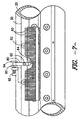
- a representative module is depicted from the substrate side and the machine side, respectively, in Figs. 5 and 6.
- Fig. 4 shows the module of Figs. 5 and 6 looking from one end of the module.
- Module 50 is mounted onto the secondary dye manifold 30 by means of machine bolts 52 (see Fig. 3). As bolts 52 are tightened, they are configured to exert a lateral force on module 50 in the direction of the orifices in orifice plate 34 (e.g., to the left in Fig. 3). This allows the position of module 50 to be adjusted along the manifold axis direction. When the desired position is reached, bolts 52 are tightened, thereby forcing the leading edge of the "Z'-shaped module 50 against the cooperatively shaped angular groove in the orifice plate 34, thereby locking the position of module 50 with respect to the orifices in orifice plate 34. Other conventional mechanisms that provide the ability to move and secure the module along the length of the secondary dye manifold (i.e., along the long axis of the gun bar) can also be used.
- positioning notch 64 which, in the preferred embodiment shown, is generally "U'-shaped, but can have other profiles, was placed' along the module edge, on the machine side of Z-shaped module 50, as shown in Fig. 6.
- Co-acting with positioning notch 64 is pivoted positioning lever 80 (Fig. 7).
- Positioning lever 80 is attached to secondary dye manifold 30 by means of pivot 82, with one end of positioning level inserted into positioning notch 64 and the opposite, rounded end of positioning lever 80 being inserted into adjustment clamp 90.
- Adjustment clamp 90 consists of an adjustment screw 92 that passes through a threaded stationary bolt attached to the outside surface of secondary dye manifold 30.
- Adjustment screw 92 has a spool 94 formed on one end which is sized to accommodate the rounded end of positioning lever 80 in a close, but not tightly fitting, relationship.
- the module 50 may be precisely aligned by loosening bolts 52 used to secure the module 50 to the secondary dye manifold 30. The module may then be moved laterally by turning adjustment screw 92 in the desired direction.
- the sides of spool 94 press on lever 80 and induce lateral movement in module 50 in a highly controlled manner.
Landscapes
- Engineering & Computer Science (AREA)
- Chemical & Material Sciences (AREA)
- Materials Engineering (AREA)
- Textile Engineering (AREA)
- Treatment Of Fiber Materials (AREA)
- Mechanical Treatment Of Semiconductor (AREA)
- Iron Core Of Rotating Electric Machines (AREA)
- Ultra Sonic Daignosis Equipment (AREA)
- Sampling And Sample Adjustment (AREA)
Claims (3)
- Dispositif de traçage pour le traçage sur un substrat en mouvement (40) dans lequel une multiplicité e courants discrets de colorant est formée par une rangée de jets de colorant (34) positionnés sur la longueur d'un collecteur de colorant allongé (30), ledit collecteur étant positionné avec son axe principal transversal à la trajectoire dudit substrat, lesdits jets formant une rangée de courants de colorant parallèles, s'étendant transversalement à ladite trajectoire de substrat, qui sont dirigés sur la surface dudit substrat et, en fonction des données de traçage, sont déviés à l'écart dudit substrat par des courants d'intersection respectifs d'un fluide de commande délivré par une rangée de tubes de commande (60) positionnés à l'avant de, et en alignement avec lesdits jets de colorant (34), ledit alignement étant obtenu par une plaque de montage rectangulaire (50), sur laquelle lesdits tubes de commande (60) sont fixés, ladite plaque de montage (50) étant associée à et s'étendant parallèlement audit axe principal dudit collecteur de colorant (30), ladite plaque de montage (50) ayant un bord avant et un bord arrière parallèle audit bord avant, lesdits tubes de commande (60) ayant des orifices qui sont positionnés en alignement le long dudit bord arrière, en avant des jets de colorant respectifs (34),
caractérisé en ce que ledit bord avant de ladite plaque de montage (50) a une encoche de positionnement (64) dans laquelle est insérée une extrémité d'un levier de positionnement pivotant (80) associé de manière opérationnelle audit collecteur de colorant, l'extrémité opposée dudit levier (80) étant insérée dans des moyens filetés (90) grâce auxquels une force latérale peut être exercée par l'intermédiaire dudit levier sur ladite encoche de positionnement (64), ladite force étant orientée afin de pousser ladite plaque de montage (50) dans une direction parallèle à l'axe principal dudit collecteur de colorant d'une manière commandée, de sorte que lesdits tubes de commande (60) peuvent être amenés en alignement latéral avec leurs jets de colorant respectifs (34). - Dispositif de traçage selon la revendication 1, dans lequel lesdits tubes de commande (60) sont fixés sur ladite plaque de montage (50) en étant positionnées dans des alésages dans ladite plaque de montage.
- Dispositif de traçage selon la revendication 1 ou 2, dans lequel lesdits moyens filetés (90) se composent d'une vis de réglage (92) ayant une bobine (94) prévue pour recevoir ladite extrémité opposée dudit levier (80) et dans lequel les côtés de ladite bobine (94) appuient sur ladite extrémité opposée dudit levier et induisent un mouvement latéral de ladite plaque de montage (50).
Applications Claiming Priority (5)
| Application Number | Priority Date | Filing Date | Title |
|---|---|---|---|
| US19371600P | 2000-03-31 | 2000-03-31 | |
| US193716P | 2000-03-31 | ||
| US821912 | 2001-03-30 | ||
| US09/821,912 US6343493B2 (en) | 2000-03-31 | 2001-03-30 | Alignment system for patterning device |
| PCT/US2001/010532 WO2001075207A1 (fr) | 2000-03-31 | 2001-03-31 | Dispositif de formation de motifs |
Publications (2)
| Publication Number | Publication Date |
|---|---|
| EP1268908A1 EP1268908A1 (fr) | 2003-01-02 |
| EP1268908B1 true EP1268908B1 (fr) | 2005-05-25 |
Family
ID=26889278
Family Applications (1)
| Application Number | Title | Priority Date | Filing Date |
|---|---|---|---|
| EP01923005A Expired - Lifetime EP1268908B1 (fr) | 2000-03-31 | 2001-03-31 | Dispositif de formation de motifs |
Country Status (10)
| Country | Link |
|---|---|
| US (1) | US6343493B2 (fr) |
| EP (1) | EP1268908B1 (fr) |
| JP (1) | JP2003531304A (fr) |
| CN (1) | CN1419616A (fr) |
| AT (1) | ATE296374T1 (fr) |
| AU (1) | AU782752B2 (fr) |
| BR (1) | BR0109140A (fr) |
| CA (1) | CA2399312A1 (fr) |
| DE (1) | DE60111035D1 (fr) |
| WO (1) | WO2001075207A1 (fr) |
Families Citing this family (3)
| Publication number | Priority date | Publication date | Assignee | Title |
|---|---|---|---|---|
| US20120034388A1 (en) * | 2010-08-04 | 2012-02-09 | Love Iii Franklin S | Apparatus and method for controlled application of liquid streams to a substrate |
| US20120031327A1 (en) * | 2010-08-04 | 2012-02-09 | Love Iii Franklin S | Apparatus for controlled application of liquid streams to a substrate with diverted liquid collection system |
| US20120031328A1 (en) * | 2010-08-04 | 2012-02-09 | Love Iii Franklin S | Apparatus for controlled application of liquid streams to a substrate with impingement jet mounting system |
Family Cites Families (8)
| Publication number | Priority date | Publication date | Assignee | Title |
|---|---|---|---|---|
| US3939675A (en) | 1974-05-17 | 1976-02-24 | Deering Milliken Research Corporation | Apparatus for dyeing and printing materials having improved means for support thereof |
| US4055868A (en) | 1976-11-29 | 1977-11-01 | Milliken Research Corporation | Dyeing method |
| US4309881A (en) | 1980-04-21 | 1982-01-12 | Milliken Research Corporation | Apparatus for the application of liquids to moving materials |
| US4584854A (en) * | 1984-10-09 | 1986-04-29 | Milliken Research Corporation | Air comb arrangement for jet dyeing machine |
| US4923743A (en) | 1987-06-15 | 1990-05-08 | Milliken Research Corporation | Apparatus and method for spraying moving substrates |
| US4984169A (en) | 1989-03-23 | 1991-01-08 | Milliken Research Corp. | Data loading and distributing process and apparatus for control of a patterning process |
| US5161395A (en) * | 1991-10-24 | 1992-11-10 | Milliken Research Corporation | Apparatus for dyeing and printing materials having improved means for support thereof |
| US5325556A (en) * | 1993-07-07 | 1994-07-05 | Milliken Research Corporation | Method and apparatus for measuring the position of a dye deflector blade |
-
2001
- 2001-03-30 US US09/821,912 patent/US6343493B2/en not_active Expired - Fee Related
- 2001-03-31 CN CN01807273A patent/CN1419616A/zh active Pending
- 2001-03-31 AU AU49745/01A patent/AU782752B2/en not_active Ceased
- 2001-03-31 AT AT01923005T patent/ATE296374T1/de not_active IP Right Cessation
- 2001-03-31 BR BR0109140-9A patent/BR0109140A/pt not_active Application Discontinuation
- 2001-03-31 CA CA002399312A patent/CA2399312A1/fr not_active Abandoned
- 2001-03-31 EP EP01923005A patent/EP1268908B1/fr not_active Expired - Lifetime
- 2001-03-31 DE DE60111035T patent/DE60111035D1/de not_active Expired - Lifetime
- 2001-03-31 JP JP2001573077A patent/JP2003531304A/ja active Pending
- 2001-03-31 WO PCT/US2001/010532 patent/WO2001075207A1/fr not_active Ceased
Also Published As
| Publication number | Publication date |
|---|---|
| AU782752B2 (en) | 2005-08-25 |
| US6343493B2 (en) | 2002-02-05 |
| WO2001075207A1 (fr) | 2001-10-11 |
| EP1268908A1 (fr) | 2003-01-02 |
| ATE296374T1 (de) | 2005-06-15 |
| CN1419616A (zh) | 2003-05-21 |
| US20010025515A1 (en) | 2001-10-04 |
| DE60111035D1 (de) | 2005-06-30 |
| JP2003531304A (ja) | 2003-10-21 |
| CA2399312A1 (fr) | 2001-10-11 |
| BR0109140A (pt) | 2003-04-22 |
| AU4974501A (en) | 2001-10-15 |
Similar Documents
| Publication | Publication Date | Title |
|---|---|---|
| CA2034331C (fr) | Appareil d'isolement monte dans un reseau de fluides et methode connexe | |
| US4309881A (en) | Apparatus for the application of liquids to moving materials | |
| CA1038183A (fr) | Appareil pour la deposition d'un liquide sur un tisse en defilement | |
| US3942343A (en) | Apparatus for dyeing and printing materials having improved dye recirculation means | |
| US4095444A (en) | Apparatus for the application of liquids to moving materials | |
| US4828174A (en) | Method and apparatus for interrupting fluid streams | |
| US6343493B2 (en) | Alignment system for patterning device | |
| US3939675A (en) | Apparatus for dyeing and printing materials having improved means for support thereof | |
| US4059880A (en) | Method of making an apparatus for dyeing and printing of materials | |
| US3985006A (en) | Dyeing and printing of materials | |
| US5211339A (en) | Apparatus for dispersing and directing dye onto a substrate | |
| US20060162597A1 (en) | Integrated Ink Rail Assembly For A Printing Press | |
| US5179749A (en) | Seamless modular tile | |
| US4584854A (en) | Air comb arrangement for jet dyeing machine | |
| US4202189A (en) | Apparatus for the application of liquids to moving materials | |
| US5161395A (en) | Apparatus for dyeing and printing materials having improved means for support thereof | |
| US4616794A (en) | Air comb arrangement for jet dyeing machine | |
| KR0172668B1 (ko) | 금속화된 웨브를 분리하고 플래튼 프레스 내에서 시트를 정지시키는 송풍기 장치 | |
| US5159824A (en) | Apparatus for high velocity dye drainage | |
| NO140603B (no) | Straale-fargeapparat. | |
| US5367733A (en) | Method and apparatus for liquid deflection | |
| EP0121290B1 (fr) | Procédé et installation pour la production thermique de motifs sur des substrats textiles | |
| EP0496394B1 (fr) | Dispositif pour la protection de filières | |
| JPH09164358A (ja) | ホットメルト接着剤塗布装置およびホットメルト接着剤塗布方法 | |
| DK173817B1 (da) | Apparat til ændring af overfladeudseendet eller texturen af et tekstilstof |
Legal Events
| Date | Code | Title | Description |
|---|---|---|---|
| PUAI | Public reference made under article 153(3) epc to a published international application that has entered the european phase |
Free format text: ORIGINAL CODE: 0009012 |
|
| 17P | Request for examination filed |
Effective date: 20020910 |
|
| AK | Designated contracting states |
Kind code of ref document: A1 Designated state(s): AT BE CH CY DE DK ES FI FR GB GR IE IT LI LU MC NL PT SE TR |
|
| AX | Request for extension of the european patent |
Free format text: AL;LT;LV;MK;RO;SI |
|
| 17Q | First examination report despatched |
Effective date: 20031103 |
|
| GRAP | Despatch of communication of intention to grant a patent |
Free format text: ORIGINAL CODE: EPIDOSNIGR1 |
|
| GRAS | Grant fee paid |
Free format text: ORIGINAL CODE: EPIDOSNIGR3 |
|
| GRAA | (expected) grant |
Free format text: ORIGINAL CODE: 0009210 |
|
| AK | Designated contracting states |
Kind code of ref document: B1 Designated state(s): AT BE CH CY DE DK ES FI FR GB GR IE IT LI LU MC NL PT SE TR |
|
| PG25 | Lapsed in a contracting state [announced via postgrant information from national office to epo] |
Ref country code: IT Free format text: LAPSE BECAUSE OF FAILURE TO SUBMIT A TRANSLATION OF THE DESCRIPTION OR TO PAY THE FEE WITHIN THE PRESCRIBED TIME-LIMIT;WARNING: LAPSES OF ITALIAN PATENTS WITH EFFECTIVE DATE BEFORE 2007 MAY HAVE OCCURRED AT ANY TIME BEFORE 2007. THE CORRECT EFFECTIVE DATE MAY BE DIFFERENT FROM THE ONE RECORDED. Effective date: 20050525 Ref country code: TR Free format text: LAPSE BECAUSE OF FAILURE TO SUBMIT A TRANSLATION OF THE DESCRIPTION OR TO PAY THE FEE WITHIN THE PRESCRIBED TIME-LIMIT Effective date: 20050525 Ref country code: LI Free format text: LAPSE BECAUSE OF FAILURE TO SUBMIT A TRANSLATION OF THE DESCRIPTION OR TO PAY THE FEE WITHIN THE PRESCRIBED TIME-LIMIT Effective date: 20050525 Ref country code: CH Free format text: LAPSE BECAUSE OF FAILURE TO SUBMIT A TRANSLATION OF THE DESCRIPTION OR TO PAY THE FEE WITHIN THE PRESCRIBED TIME-LIMIT Effective date: 20050525 Ref country code: NL Free format text: LAPSE BECAUSE OF FAILURE TO SUBMIT A TRANSLATION OF THE DESCRIPTION OR TO PAY THE FEE WITHIN THE PRESCRIBED TIME-LIMIT Effective date: 20050525 Ref country code: FI Free format text: LAPSE BECAUSE OF FAILURE TO SUBMIT A TRANSLATION OF THE DESCRIPTION OR TO PAY THE FEE WITHIN THE PRESCRIBED TIME-LIMIT Effective date: 20050525 Ref country code: AT Free format text: LAPSE BECAUSE OF FAILURE TO SUBMIT A TRANSLATION OF THE DESCRIPTION OR TO PAY THE FEE WITHIN THE PRESCRIBED TIME-LIMIT Effective date: 20050525 Ref country code: BE Free format text: LAPSE BECAUSE OF FAILURE TO SUBMIT A TRANSLATION OF THE DESCRIPTION OR TO PAY THE FEE WITHIN THE PRESCRIBED TIME-LIMIT Effective date: 20050525 |
|
| REG | Reference to a national code |
Ref country code: GB Ref legal event code: FG4D |
|
| REG | Reference to a national code |
Ref country code: CH Ref legal event code: EP |
|
| REG | Reference to a national code |
Ref country code: IE Ref legal event code: FG4D |
|
| REF | Corresponds to: |
Ref document number: 60111035 Country of ref document: DE Date of ref document: 20050630 Kind code of ref document: P |
|
| PG25 | Lapsed in a contracting state [announced via postgrant information from national office to epo] |
Ref country code: DK Free format text: LAPSE BECAUSE OF FAILURE TO SUBMIT A TRANSLATION OF THE DESCRIPTION OR TO PAY THE FEE WITHIN THE PRESCRIBED TIME-LIMIT Effective date: 20050825 Ref country code: GR Free format text: LAPSE BECAUSE OF FAILURE TO SUBMIT A TRANSLATION OF THE DESCRIPTION OR TO PAY THE FEE WITHIN THE PRESCRIBED TIME-LIMIT Effective date: 20050825 Ref country code: SE Free format text: LAPSE BECAUSE OF FAILURE TO SUBMIT A TRANSLATION OF THE DESCRIPTION OR TO PAY THE FEE WITHIN THE PRESCRIBED TIME-LIMIT Effective date: 20050825 |
|
| PG25 | Lapsed in a contracting state [announced via postgrant information from national office to epo] |
Ref country code: DE Free format text: LAPSE BECAUSE OF FAILURE TO SUBMIT A TRANSLATION OF THE DESCRIPTION OR TO PAY THE FEE WITHIN THE PRESCRIBED TIME-LIMIT Effective date: 20050826 |
|
| PG25 | Lapsed in a contracting state [announced via postgrant information from national office to epo] |
Ref country code: ES Free format text: LAPSE BECAUSE OF FAILURE TO SUBMIT A TRANSLATION OF THE DESCRIPTION OR TO PAY THE FEE WITHIN THE PRESCRIBED TIME-LIMIT Effective date: 20050905 |
|
| PG25 | Lapsed in a contracting state [announced via postgrant information from national office to epo] |
Ref country code: PT Free format text: LAPSE BECAUSE OF FAILURE TO SUBMIT A TRANSLATION OF THE DESCRIPTION OR TO PAY THE FEE WITHIN THE PRESCRIBED TIME-LIMIT Effective date: 20051027 |
|
| REG | Reference to a national code |
Ref country code: CH Ref legal event code: PL |
|
| NLV1 | Nl: lapsed or annulled due to failure to fulfill the requirements of art. 29p and 29m of the patents act | ||
| PG25 | Lapsed in a contracting state [announced via postgrant information from national office to epo] |
Ref country code: IE Free format text: LAPSE BECAUSE OF NON-PAYMENT OF DUE FEES Effective date: 20060331 Ref country code: LU Free format text: LAPSE BECAUSE OF NON-PAYMENT OF DUE FEES Effective date: 20060331 Ref country code: MC Free format text: LAPSE BECAUSE OF NON-PAYMENT OF DUE FEES Effective date: 20060331 |
|
| PLBE | No opposition filed within time limit |
Free format text: ORIGINAL CODE: 0009261 |
|
| STAA | Information on the status of an ep patent application or granted ep patent |
Free format text: STATUS: NO OPPOSITION FILED WITHIN TIME LIMIT |
|
| ET | Fr: translation filed | ||
| 26N | No opposition filed |
Effective date: 20060228 |
|
| REG | Reference to a national code |
Ref country code: IE Ref legal event code: MM4A |
|
| PGFP | Annual fee paid to national office [announced via postgrant information from national office to epo] |
Ref country code: GB Payment date: 20080327 Year of fee payment: 8 |
|
| PGFP | Annual fee paid to national office [announced via postgrant information from national office to epo] |
Ref country code: FR Payment date: 20080317 Year of fee payment: 8 |
|
| PG25 | Lapsed in a contracting state [announced via postgrant information from national office to epo] |
Ref country code: CY Free format text: LAPSE BECAUSE OF FAILURE TO SUBMIT A TRANSLATION OF THE DESCRIPTION OR TO PAY THE FEE WITHIN THE PRESCRIBED TIME-LIMIT Effective date: 20050525 |
|
| GBPC | Gb: european patent ceased through non-payment of renewal fee |
Effective date: 20090331 |
|
| REG | Reference to a national code |
Ref country code: FR Ref legal event code: ST Effective date: 20091130 |
|
| PG25 | Lapsed in a contracting state [announced via postgrant information from national office to epo] |
Ref country code: GB Free format text: LAPSE BECAUSE OF NON-PAYMENT OF DUE FEES Effective date: 20090331 Ref country code: FR Free format text: LAPSE BECAUSE OF NON-PAYMENT OF DUE FEES Effective date: 20091123 |