EP1269211B1 - Appareil d'imagerie par resonance magnetique dote d'un moyen de filtrage des champs rf - Google Patents
Appareil d'imagerie par resonance magnetique dote d'un moyen de filtrage des champs rf Download PDFInfo
- Publication number
- EP1269211B1 EP1269211B1 EP01908009A EP01908009A EP1269211B1 EP 1269211 B1 EP1269211 B1 EP 1269211B1 EP 01908009 A EP01908009 A EP 01908009A EP 01908009 A EP01908009 A EP 01908009A EP 1269211 B1 EP1269211 B1 EP 1269211B1
- Authority
- EP
- European Patent Office
- Prior art keywords
- magnetic resonance
- screen
- magnetic
- array
- screens
- Prior art date
- Legal status (The legal status is an assumption and is not a legal conclusion. Google has not performed a legal analysis and makes no representation as to the accuracy of the status listed.)
- Expired - Lifetime
Links
- 238000002595 magnetic resonance imaging Methods 0.000 title claims abstract description 15
- 238000012216 screening Methods 0.000 claims abstract description 8
- 230000035699 permeability Effects 0.000 claims description 32
- 239000000463 material Substances 0.000 claims description 13
- 239000004020 conductor Substances 0.000 claims description 10
- 230000004907 flux Effects 0.000 claims description 9
- 230000005670 electromagnetic radiation Effects 0.000 claims description 8
- 230000005284 excitation Effects 0.000 claims description 5
- 230000001747 exhibiting effect Effects 0.000 claims description 3
- 230000001939 inductive effect Effects 0.000 claims description 2
- 230000005855 radiation Effects 0.000 claims description 2
- 230000004044 response Effects 0.000 claims description 2
- 238000003491 array Methods 0.000 description 4
- 239000010410 layer Substances 0.000 description 3
- 230000035945 sensitivity Effects 0.000 description 3
- 229920002799 BoPET Polymers 0.000 description 2
- 239000005041 Mylar™ Substances 0.000 description 2
- 239000004411 aluminium Substances 0.000 description 2
- XAGFODPZIPBFFR-UHFFFAOYSA-N aluminium Chemical compound [Al] XAGFODPZIPBFFR-UHFFFAOYSA-N 0.000 description 2
- 229910052782 aluminium Inorganic materials 0.000 description 2
- 230000008901 benefit Effects 0.000 description 2
- 239000000696 magnetic material Substances 0.000 description 2
- 239000003973 paint Substances 0.000 description 2
- 239000000758 substrate Substances 0.000 description 2
- RYGMFSIKBFXOCR-UHFFFAOYSA-N Copper Chemical compound [Cu] RYGMFSIKBFXOCR-UHFFFAOYSA-N 0.000 description 1
- BQCADISMDOOEFD-UHFFFAOYSA-N Silver Chemical compound [Ag] BQCADISMDOOEFD-UHFFFAOYSA-N 0.000 description 1
- 230000005540 biological transmission Effects 0.000 description 1
- 239000003990 capacitor Substances 0.000 description 1
- 230000008859 change Effects 0.000 description 1
- 229910052802 copper Inorganic materials 0.000 description 1
- 239000010949 copper Substances 0.000 description 1
- 230000008878 coupling Effects 0.000 description 1
- 238000010168 coupling process Methods 0.000 description 1
- 238000005859 coupling reaction Methods 0.000 description 1
- 239000003989 dielectric material Substances 0.000 description 1
- 238000002474 experimental method Methods 0.000 description 1
- 239000003292 glue Substances 0.000 description 1
- 238000010348 incorporation Methods 0.000 description 1
- 239000011229 interlayer Substances 0.000 description 1
- 230000005389 magnetism Effects 0.000 description 1
- 238000000034 method Methods 0.000 description 1
- 238000012545 processing Methods 0.000 description 1
- 229910052709 silver Inorganic materials 0.000 description 1
- 239000004332 silver Substances 0.000 description 1
- 238000004611 spectroscopical analysis Methods 0.000 description 1
Images

Classifications
-
- G—PHYSICS
- G01—MEASURING; TESTING
- G01R—MEASURING ELECTRIC VARIABLES; MEASURING MAGNETIC VARIABLES
- G01R33/00—Arrangements or instruments for measuring magnetic variables
- G01R33/20—Arrangements or instruments for measuring magnetic variables involving magnetic resonance
- G01R33/28—Details of apparatus provided for in groups G01R33/44 - G01R33/64
- G01R33/42—Screening
- G01R33/422—Screening of the radio frequency field
-
- G—PHYSICS
- G01—MEASURING; TESTING
- G01R—MEASURING ELECTRIC VARIABLES; MEASURING MAGNETIC VARIABLES
- G01R33/00—Arrangements or instruments for measuring magnetic variables
- G01R33/20—Arrangements or instruments for measuring magnetic variables involving magnetic resonance
- G01R33/28—Details of apparatus provided for in groups G01R33/44 - G01R33/64
- G01R33/32—Excitation or detection systems, e.g. using radio frequency signals
- G01R33/34—Constructional details, e.g. resonators, specially adapted to MR
- G01R33/341—Constructional details, e.g. resonators, specially adapted to MR comprising surface coils
- G01R33/3415—Constructional details, e.g. resonators, specially adapted to MR comprising surface coils comprising arrays of sub-coils, i.e. phased-array coils with flexible receiver channels
Definitions
- This invention relates to magnetic resonance imaging.
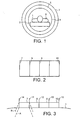
- a typical magnetic resonance imaging apparatus is shown in Figure 1.
- a patient 1 on a couch 2 is slid into the bore 3 of an annular electromagnet, typically a superconducting electromagnet.
- a main magnetic field is generated in alignment with the axis of the bore, and gradient coils (not shown) are provided to set up magnetic field gradients for example along the z-direction along the axis of the bore, and along x and y directions in the radial plane.
- a transmit coil 4 surrounds the patient and transmits pulses of r.f. energy to excite to resonance magnetic resonance active nuclei such as protons in the region of the patient to be examined. This transmit coil 4 is normally surrounded by an r.f.
- the transmit coil 4 can be also be used to receive the magnetic resonance signals which result from the resonating protons in the region of interest, although a separate receive coil is often provided.
- a coil placed in the vicinity of the surface of the patient is used to receive the magnetic resonance signals, such as the coil 6 (shown on an enlarged scale in Figure 2).
- the sensitive region of each coil of the array matches better the region it is desired to image than would one large receive coil, and more signal can therefore be collected from the region of interest. It could also be that the localised view of the region it is desired to image obtained from each coil of the array can be used to advantage to reduce the number of encoding steps (WO-A-98/21600).
- US-A-5363845 discloses a receiver coil comprising a first and a second coil for an MRI apparatus, wherein a radio-frequency shield is positioned between the first and second coils to limit the sensitivity of the coils to respective volumes.
- a shielding between coils is also discussed in US-A-5804969, which mentions the problem of cross-talk between two MRI RF coils when they are operated in close proximity.
- the document suggests using a decoupling capacitor so that the coils need not be RF-shielded from one another or carefully positioned (e.g. overlapped) to reduce or eliminate mutual inductance.
- microstructures with magnetic properties comprising an array of capacitive elements made from non-magnetic conducting material can exhibit magnetic permeability at radio frequencies (IEEE Transactions on Microwave Theory and Techniques, Vol. 47, No. 11, November 1999, Magnetism from Conductors and Enhanced Non-Linear Phenomena by J B Pendry, A J Holden, D J Robbins and W J Stewart).
- the invention provides magnetic resonance apparatus, in which resonance is excited in use in magnetic resonant active nuclei in a region of an object in the presence of a main magnetic field, which magnetic resonance apparatus includes a structure with magnetic properties forming a screen to screen r.f.
- the structure comprising an array of capacitive elements which are one of planar rings, spirals or rolls of conductive material, the array exhibiting a predetermined magnetic permeability in response to incident electromagnetic radiation lying within a predetermined frequency band, the magnetic component of the electromagnetic radiation lying within the predetermined frequency band inducing an electrical current to flow within said planar rings, spirals or rolls of conductive material, respectively, wherein the spacing of the elements is less than the wavelength of the radiation within the predetermined frequency band, and wherein the dimensions of the capacitive elements and their spacing apart are selected such as to provide a magnetic permeability appropriate to that of a screen to electromagnetic radiation in that predetermined frequency band.
- the screen may be capable of exhibiting a magnetic permeability having a zero or negative real part to electromagnetic radiation within the predetermined frequency band.
- the screen may be capable of being switched between this value, and the permeability of free space.
- the screens of the structure with magnetic properties are however capable of use for any purpose in magnetic resonance apparatus, which may be magnetic resonance imaging apparatus or magnetic resonance spectroscopy apparatus, since the screens are non-magnetic in a steady magnetic field.
- the screen will typically be tuned to the magnetic resonance frequency, but could be tuned to one or more different frequencies, for example, if it was desired to prevent interference of a particular external r.f. source with a magnetic resonance experiment.
- the invention also provides magnetic resonance imaging apparatus, in which resonance is excited in use in magnetic resonant active nuclei in a region of an object in the presence of a main magnetic field, which magnetic resonance imaging apparatus includes the said microstructured magnetic material to shield regions of the object it is not desired to image from r.f. excitation applied to the region it is desired to image.
- the receive coil arrays shown in Figures 2 to 5, Figures 6 to 8, and Figure 9 are intended to be used as the receive coil 6 in the known magnetic resonance imaging apparatus of Figure 1.
- the receive coil 6 comprises an array of four coils 7, 8, 9, 10 which are spaced from each other by respective vertically arranged (as seen in Figure 3) screens 11, 12, 13, with further screens 14 and 15 being positioned at the ends of the array.
- each screen is of the form shown in Figure 4.
- Each receive coil 7 to 10 is connected to a separate channel of processing means for the magnetic resonance imaging apparatus, and the outputs of the four coils are combined in known ways.
- Arrays of receive coils are of course known but, while screens have also been used between the coils of the array, the coils would have been mounted on the surface of the patient.
- each coil is indicated by the dotted lines indicated by the reference A, and the combination of the signals from the four coils can be used to obtain an image of a region inside the patient 1.
- each of the screens 11 to 15 is switchable so that it either acts as a conventional screen, or it acts as if there is no screen present.
- the field of view of each coil is now given by the dotted lines indicated with reference B, and this corresponds to the signal from a different region of the patient being collected.
- the screens 11 to 15 are advantageously made of microstructures comprising an array of capacitive elements made from non-magnetic conducting material which exhibits magnetic permeability at radio frequencies, while being non-magnetic in steady magnetic fields, as described in the aforementioned IEEE paper. Screening will take place when the real part of the magnetic permeability of the microstructured material is zero or negative, for then there exists no solutions to Maxwell's equations. This condition is met for a range of frequencies lying between the frequency at which the microstructured material has a magnetic permeability having a resonant variation which diverges at an angular resonant frequency ⁇ 0 , and a magnetic plasma frequency ⁇ 0 at which the effective magnetic permeability is equal to zero.
- the screening properties are controllable by the incorporation of switchable permitivity materials into the structured magnetic materials.
- the screens 11 to 15 may be controlled so as to be switchable between an operative state having a negative or zero real permeability (the imaginary component of permeability could be any value for negative real permeability and could be a high value for zero real permeability) and an inoperative state in which the real permeability is greater than or equal to unity, both conditions applying at the magnetic resonance frequency.
- the real permeability would be unity, but there could be advantages in the real permeability being in excess of unity.
- the screens are not affected by the main magnetic field or gradient fields in any of its states, operative or inoperative; that is, the screen is non-magnetic i.e. has the magnetic permeability of free space i.e. a relative permeability of unity in those conditions.
- the screens can be controlled so that the screening property is always maintained above the line 16, but can be switched on and off below the line 16.
- a separately switchable section 17 may be provided, so that the section above the line 16 acts as a screen, and the sections between the lines 16 and 17, and below the line 17, respectively, are individually switchable between operative (screening) and inoperative states. This would provide a third area of coverage from the two areas A, B shown in Figure 3.
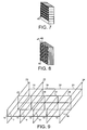
- the screens could be made of rolls of non-magnetic conductor on an insulating substrate, such as 29, 30, 31 in Figure 5.
- the rolls extend from face to face of the screen i.e. normal to the surface of each screen, and are closely packed together. Only a few sample rolls are shown in Figure 5.
- the dimensions of the rolls and their spacing is chosen to provide zero or negative real part of refractive index.
- Magnetic flux which threads along the axes of the rolls is absorbed (zero real permeability) or reflected (negative real permeability), so that flux from signal sources in the patient is only received from field of view A in Figure 3 when the screens are operative, since flux impinging on the outer surfaces of the screens on each side of coil 7 cannot couple with coil 7.
- the capacitive elements could be formed by columns of planar elements.
- an array of five coils 32-36 is screened by four screens 37-40 with a further two screens 41, 42 on the ends of the array, seen in Figure 6 in a view corresponding to that of Figure 3.
- the perspective views of the alternative forms of screens shown in Figures 7 and 8 are not drawn to scale.
- the screens block the transverse component of the r.f. flux such as 43, 45: that reduces the field of view and prevents the coils from coupling.
- the component of the flux that is normal to the plane of the screens 37-40 must be prevented from crossing from one coil to another. This means that the component of the permeability of the screens in a direction normal to their faces must be controlled.
- the components of the permeability of the screen in orthogonal directions, that is, in the plane of the screens, are not switchable. So the orientation of the material needs to be shown in Figures 7 and 8. In both cases, the axis of the structure needs to be normal to their faces, transverse to the axes of the coils 32-36.
- Figure 7 shows each screen in perspective view, with rolls of non-magnetic conductor on an insulating substrate, such as 45, similar to the rolls 29 to 31 of Figure 5.
- the rolls extend from face to face of the screen 4.
- a switchable dielectric e.g. BST paint could be used between conducting layers. This would reduce the resonant frequency so that the region with ⁇ 0, which lies above the resonant frequency, was now at the operating frequency, When switched, the resonant frequency is increased, and ⁇ becomes positive again.
- ProFilm Trade Mark
- Mylar Trade Mark
- glue layer for ProFilm (Trade Mark) (Mylar (Trade Mark) base coated with 10nm of aluminium and a glue layer to give a total film of about 50 ⁇ m thickness, sheet resistance about 2.7 ⁇ /square)
- the materials may be assembled in hexagonal close packed lattices (i.e. as closely packed as possible).
- the screen is made from a number of printed circuit boards such as 47, 48.
- Each board carries an array of capacitive loops 46, which form columns of loops with the loops of the other boards.
- the columns extend normal to the faces of the screens.
- the elements may be spirals. Typical dimensions would be:-
- a switchable dielectric material e.g. BST paint
- the permeability at 2 1.3 MHz is shown below ⁇ ⁇ ⁇ ⁇ ⁇ ⁇ 50 -1.57 + 0.01i 46 -101 + 15.7i 40 2.42 + 0.003i 49 -2.33+0.016i 45.9 280 + 531i 20 1.16 + 10 -5 i 48 -3.82 + 0.034i 45 11.4 + 0.16i 47 -8.03 + 0.121i 44 5.85 + 0.035i So by controlling the permittivity of the dielectric in the gaps, we can control the permeability over the whole range of interesting values.
- the controllability of the screens enables the sensitivity profiles of the coils of the array to be reconfigured for different scanning operations. Further, the individual coil sensitivity profiles could be varied during the course of a scan to achieve improved performance.
- the invention is not of course restricted to arrays of four coils or five coils as shown in Figures 2 and 3, and Figure 6, respectively.
- the array may be larger, and multiple individually controlled screens between each segment would then permit a change both of the apparent size of coils, but also optimisation of the field of view of each coil so as to achieve maximal encoding gains as in WO-A-98/21600.
- the coil shown in Figures 2 and 3, or Figure 6 and larger or smaller versions similar thereto, may also be used for transmitting the r.f. excitation pulse for exciting resonance in magnetic resonant active nuclei, as well as for receiving the r.f. relaxation signals.
- By controlling the screens it is possible to employ a different shape and size of r.f field during transmission and during reception.
- a further set of coils 18 to 21 is employed, separated by controllable screens only one of which 22 is shown, with end screens 23 and 24. In this case, however, separate screens 25 to 28 are employed between the two arrays themselves.
- the screens are all made of the same material as that described above.
- the screens are not restricted to use between array coils. Thus, it is customary for the entire magnetic resonance apparatus to be housed in a copper clad room, to prevent external r.f. disturbances affecting the collection of data.
- the screens of microstructured material could be used for this purpose, and in this case, it is not necessary for the permeability to be controllable. The screen simply needs to reflect or absorb external r.f. energy at the magnetic resonance frequency.
- the microstructured material could form a lining for the room housing the magnetic resonance apparatus.
- the microstructured material can be used to prevent aliasing. This arises when the r.f. excitation pulses excite regions of an object e.g. a patient outside the desired region, so that the data collected comes partly from this region and partly from the unwanted region.
- the screen of microstructured material is draped over the unwanted region, and shields it from the r.f. excitation pulses. Aliasing is thus reduced or eliminated.
- the magnet is an electromagnet in Figure 1
- the invention is also applicable to open magnets such as permanent magnets.
- the screen may be non-magnetic in audio-frequency magnetic fields.
Landscapes
- Physics & Mathematics (AREA)
- Health & Medical Sciences (AREA)
- Epidemiology (AREA)
- Condensed Matter Physics & Semiconductors (AREA)
- General Physics & Mathematics (AREA)
- Magnetic Resonance Imaging Apparatus (AREA)
Claims (10)
- Appareil de résonance magnétique, dans lequel la résonance magnétique est excitée en service dans des noyaux actifs résonnants magnétiques dans une région d'un objet (1) en présence d'un champ magnétique principal, lequel appareil de résonance magnétique comprend une structure avec des propriétés magnétiques formant un écran (11-15, 37-40, 22) pour filtrer le flux RF, la structure comprenant un ensemble d'éléments capacitifs qui sont des anneaux planaires ou des spirales (46) ou des rouleaux de matériau conducteur (29-31, 45), l'ensemble présentant une perméabilité magnétique prédéterminée en réaction au rayonnement électromagnétique incident présent dans une bande fréquence prédéterminée, la composante magnétique du rayonnement électromagnétique située dans la bande de fréquence prédéterminée induisant le passage d'un courant électrique dans les anneaux planaires, les spirales ou les rouleaux de matériau conducteur, respectivement, dans lequel l'espacement des éléments capacitifs est inférieur à la longueur d'onde du rayonnement dans la bande de fréquence prédéterminée, et dans lequel les dimensions des éléments capacitifs et leur espacement mutuel sont sélectionnés de manière à fournir la perméabilité magnétique appropriée à celle d'un écran au rayonnement électromagnétique dans cette bande de fréquence prédéterminée.
- Appareil de résonance magnétique suivant la revendication 1, dans lequel l'écran est agencé pour protéger la région dans laquelle la résonance est excitée en service, de l'énergie RF extérieure.
- Appareil de résonance magnétique suivant la revendication 1 ou 2, dans lequel l'écran est agencé pour protéger des régions de l'objet que l'on ne souhaite pas visualiser, de l'excitation RF appliquée à la région que l'on souhaite visualiser.
- Appareil de résonance magnétique suivant l'une quelconque des revendications 1 à 3, comprenant un ensemble de bobines (7-10, 32-36, 18-21) destiné à recevoir des signaux de résonance magnétique générés par les noyaux actifs résonnants magnétiques, dans lequel l'écran est disposé entre des bobines de l'ensemble.
- Appareil de résonance magnétique suivant l'une quelconque des revendications 1 à 4, dans lequel les propriétés de protection de l'écran peuvent être contrôlées grâce au fait que des matériaux de permittivité commutable sont incorporés dans la structure.
- Appareil de résonance magnétique suivant la revendication 5, comprenant un matériau de permittivité commutable associé aux éléments capacitifs afin de permettre à la perméabilité magnétique de l'écran d'être commutée entre des valeurs différentes.
- Appareil de résonance magnétique suivant l'une quelconque des revendications 1 à 6, dans lequel les éléments capacitifs prévus sous la forme de rouleaux de matériau conducteur (29-31, 45) sont disposés avec leurs axes perpendiculaires à la surface des écrans.
- Appareil de résonance magnétique suivant l'une quelconque des revendications 1 à 6, dans lequel les éléments capacitifs prévus sous la forme d'anneaux planaires ou de spirales (46) sont disposés dans des colonnes respectives et avec leurs axes perpendiculaires à la surface des écrans.
- Appareil de résonance magnétique suivant l'une quelconque des revendications 1 à 8, dans lequel l'écran présentant une perméabilité ayant une partie réelle négative ou zéro à du rayonnement électromagnétique d'une fréquence située dans la bande de fréquence prédéterminée.
- Appareil de résonance magnétique suivant l'une quelconque des revendications 1 à 9, dans lequel l'appareil est un appareil d'imagerie par résonance magnétique.
Applications Claiming Priority (3)
| Application Number | Priority Date | Filing Date | Title |
|---|---|---|---|
| GB0005354 | 2000-03-06 | ||
| GB0005354A GB2360094A (en) | 2000-03-06 | 2000-03-06 | RF screens for MRI |
| PCT/GB2001/000962 WO2001067126A1 (fr) | 2000-03-06 | 2001-03-06 | Appareil d'imagerie par resonance magnetique dote d'un moyen de filtrage des champs rf |
Publications (2)
| Publication Number | Publication Date |
|---|---|
| EP1269211A1 EP1269211A1 (fr) | 2003-01-02 |
| EP1269211B1 true EP1269211B1 (fr) | 2007-02-28 |
Family
ID=9887049
Family Applications (1)
| Application Number | Title | Priority Date | Filing Date |
|---|---|---|---|
| EP01908009A Expired - Lifetime EP1269211B1 (fr) | 2000-03-06 | 2001-03-06 | Appareil d'imagerie par resonance magnetique dote d'un moyen de filtrage des champs rf |
Country Status (8)
| Country | Link |
|---|---|
| US (1) | US6819106B2 (fr) |
| EP (1) | EP1269211B1 (fr) |
| JP (1) | JP2003526421A (fr) |
| AT (1) | ATE355535T1 (fr) |
| AU (1) | AU2001235870A1 (fr) |
| DE (1) | DE60126921T2 (fr) |
| GB (1) | GB2360094A (fr) |
| WO (1) | WO2001067126A1 (fr) |
Cited By (1)
| Publication number | Priority date | Publication date | Assignee | Title |
|---|---|---|---|---|
| WO2017118684A1 (fr) * | 2016-01-08 | 2017-07-13 | Commissariat A L'energie Atomique Et Aux Energies Alternatives | Antenne reseau, en particulier pour imagerie par resonance magnetique nucleaire, comprenant des resonateurs electromagnetiques lineaires et au moins un dispositif de decouplage |
Families Citing this family (11)
| Publication number | Priority date | Publication date | Assignee | Title |
|---|---|---|---|---|
| GB2360132B (en) | 2000-03-06 | 2002-04-24 | Marconi Caswell Ltd | Structure with switchable magnetic properties |
| GB2360137A (en) * | 2000-03-06 | 2001-09-12 | Marconi Caswell Ltd | Guides for RF magnetic flux |
| GB2360138A (en) | 2000-03-06 | 2001-09-12 | Marconi Caswell Ltd | Screens for RF magnetic flux |
| GB2360093A (en) * | 2000-03-06 | 2001-09-12 | Marconi Caswell Ltd | NMR system with magnetic flux guide |
| DE102004006322B4 (de) * | 2004-02-10 | 2013-09-12 | RAPID Biomedizinische Geräte RAPID Biomedical GmbH | Abbildungsvorrichtung zur Nutzung der kernmagnetischen Resonanz |
| EP1999479A1 (fr) * | 2006-03-22 | 2008-12-10 | Koninklijke Philips Electronics N.V. | Matrice de bobines multix blindées pour mri à champ parallèle élevé |
| DE102007017533A1 (de) * | 2007-04-13 | 2008-10-23 | Siemens Ag | Anordnung zur Abschirmung |
| MX2014004533A (es) * | 2011-10-18 | 2014-08-01 | Koninkl Philips Nv | Ensamble de bobina de imagenes de resonancia magnetica (mri) con protector de radiofrecuencia conmutable entre un estado bloqueado y un estado transparente. |
| US20150355297A1 (en) * | 2013-01-11 | 2015-12-10 | Ravi Menon | System and method for decoupling magentic resonance imaging radio frequency coils with a modular magnetic wall |
| GB2534337B (en) * | 2014-09-29 | 2017-10-18 | Iphase Ltd | Method and apparatus for monitoring of the multiphase flow in a pipe |
| CN114720926B (zh) * | 2021-03-31 | 2025-01-21 | 无锡鸣石峻致医疗科技有限公司 | 一种器官无创定量核磁共振检测系统 |
Family Cites Families (18)
| Publication number | Priority date | Publication date | Assignee | Title |
|---|---|---|---|---|
| US4439733A (en) * | 1980-08-29 | 1984-03-27 | Technicare Corporation | Distributed phase RF coil |
| JPS60190846A (ja) * | 1984-03-10 | 1985-09-28 | Jeol Ltd | 核磁気共鳴装置 |
| US5223849A (en) * | 1986-11-25 | 1993-06-29 | Chomerics, Inc. | Broadband electromagnetic energy absorber |
| US5053711A (en) * | 1990-01-19 | 1991-10-01 | General Electric Company | Nmr radio frequency coil with improved axial field homogeneity |
| US5386191A (en) * | 1993-03-01 | 1995-01-31 | The Regents Of The University Of California | RF coil providing reduced obstruction access to image volume in transverse magnet MRI system |
| US5363845A (en) * | 1993-08-13 | 1994-11-15 | Medical Advances, Inc. | Breast coil for magnetic resonance imaging |
| US5804969A (en) * | 1995-07-28 | 1998-09-08 | Advanced Mammography Systems, Inc. | MRI RF coil |
| US5760584A (en) * | 1996-08-16 | 1998-06-02 | General Electric Company | Shield for MR system RF coil provided with multiple capacitive channels for RF current flow |
| US6249006B1 (en) * | 1996-10-04 | 2001-06-19 | Matsushita Electric Industrial Co., Ltd. | Electromagnetic field shielding device |
| US5910728A (en) | 1996-11-12 | 1999-06-08 | Beth Israel Deaconess Medical Center | Simultaneous acquisition of spatial harmonics (SMASH): ultra-fast imaging with radiofrequency coil arrays |
| DE19702256A1 (de) * | 1997-01-23 | 1998-07-30 | Philips Patentverwaltung | MR-Gerät mit einer MR-Spulenanordnung |
| US6169401B1 (en) * | 1998-11-25 | 2001-01-02 | Picker International, Inc. | Flexible open quadrature highpass ladder structure RF surface coil in magnetic resonance imaging |
| EP1014102A3 (fr) * | 1998-12-24 | 2001-10-04 | Marconi Electronic Systems Limited | Imagerie par résonance magnétique à tranches multiples avec un ensemble de bobines réceptrices |
| GB9900034D0 (en) * | 1999-01-04 | 1999-02-24 | Marconi Electronic Syst Ltd | Structure with magnetic properties |
| US6441615B1 (en) * | 1999-12-28 | 2002-08-27 | Koninklijke Philips Electronics, Nv | Crossed-ladder RF coils for vertical field MRI systems |
| ATE484757T1 (de) * | 2000-02-01 | 2010-10-15 | Surgivision Inc | Transseptale nadelantenne für ein mr- bildgebungsgerät |
| GB2360137A (en) | 2000-03-06 | 2001-09-12 | Marconi Caswell Ltd | Guides for RF magnetic flux |
| GB2360132B (en) | 2000-03-06 | 2002-04-24 | Marconi Caswell Ltd | Structure with switchable magnetic properties |
-
2000
- 2000-03-06 GB GB0005354A patent/GB2360094A/en not_active Withdrawn
-
2001
- 2001-03-06 AU AU2001235870A patent/AU2001235870A1/en not_active Abandoned
- 2001-03-06 WO PCT/GB2001/000962 patent/WO2001067126A1/fr not_active Ceased
- 2001-03-06 JP JP2001566045A patent/JP2003526421A/ja not_active Abandoned
- 2001-03-06 DE DE60126921T patent/DE60126921T2/de not_active Expired - Fee Related
- 2001-03-06 AT AT01908009T patent/ATE355535T1/de not_active IP Right Cessation
- 2001-03-06 EP EP01908009A patent/EP1269211B1/fr not_active Expired - Lifetime
- 2001-03-06 US US10/220,732 patent/US6819106B2/en not_active Expired - Fee Related
Cited By (3)
| Publication number | Priority date | Publication date | Assignee | Title |
|---|---|---|---|---|
| WO2017118684A1 (fr) * | 2016-01-08 | 2017-07-13 | Commissariat A L'energie Atomique Et Aux Energies Alternatives | Antenne reseau, en particulier pour imagerie par resonance magnetique nucleaire, comprenant des resonateurs electromagnetiques lineaires et au moins un dispositif de decouplage |
| FR3046701A1 (fr) * | 2016-01-08 | 2017-07-14 | Commissariat Energie Atomique | Antenne reseau, en particulier pour imagerie par resonance magnetique nucleaire, comprenant des resonateurs electromagnetiques lineaires et au moins un dispositif de decouplage |
| US10788549B2 (en) | 2016-01-08 | 2020-09-29 | Commissariat A L'energie Atomique Et Aux Energies Alternatives | Antenna array, in particular for magnetic resonance imaging, comprising linear electromagnetic resonators and at least one decoupling device |
Also Published As
| Publication number | Publication date |
|---|---|
| DE60126921T2 (de) | 2007-09-20 |
| DE60126921D1 (de) | 2007-04-12 |
| US20030155918A1 (en) | 2003-08-21 |
| GB2360094A (en) | 2001-09-12 |
| EP1269211A1 (fr) | 2003-01-02 |
| WO2001067126A1 (fr) | 2001-09-13 |
| AU2001235870A1 (en) | 2001-09-17 |
| GB0005354D0 (en) | 2000-04-26 |
| US6819106B2 (en) | 2004-11-16 |
| JP2003526421A (ja) | 2003-09-09 |
| ATE355535T1 (de) | 2006-03-15 |
Similar Documents
| Publication | Publication Date | Title |
|---|---|---|
| US7023209B2 (en) | Method and apparatus for magnetic resonance imaging and spectroscopy using microstrip transmission line coils | |
| US7268554B2 (en) | RF coil for imaging system | |
| US6593744B2 (en) | Multi-channel RF cable trap for magnetic resonance apparatus | |
| EP0359374B1 (fr) | Appareil par résonance magnétique | |
| EP1269211B1 (fr) | Appareil d'imagerie par resonance magnetique dote d'un moyen de filtrage des champs rf | |
| US20050062472A1 (en) | Mri tunable antenna and system | |
| EP0758751A1 (fr) | Méthode et appareil d'imagerie par résonance magnétique | |
| JP2001112738A (ja) | 磁気共鳴装置のためのrf発信コイル | |
| US7532008B2 (en) | Material having magnetic permeability at R.F. frequency | |
| CN1882845A (zh) | 用于mri的混合tem/鸟笼型线圈 | |
| EP0724164A1 (fr) | Appareil et méthodes de résonance magnétique | |
| EP0356182A2 (fr) | Assemblage de bobines, spécialement pour l'appareil de résonance magnétique | |
| GB2360093A (en) | NMR system with magnetic flux guide | |
| GB2151791A (en) | RF Field coils for NMR apparatus | |
| WO2005020793A2 (fr) | Modele de bobine a microrubans pour appareil d'irm | |
| WO2010018479A1 (fr) | Bobine rf à résonance magnétique | |
| GB2373102A (en) | Structures with magnetic properties | |
| US10816620B2 (en) | Method for controlling the distribution of the RF magnetic field in a magnetic resonance imaging system | |
| US12601800B2 (en) | Metamaterial slab for MRI | |
| IL97937A (en) | Sample holder for NMR microscopy |
Legal Events
| Date | Code | Title | Description |
|---|---|---|---|
| PUAI | Public reference made under article 153(3) epc to a published international application that has entered the european phase |
Free format text: ORIGINAL CODE: 0009012 |
|
| 17P | Request for examination filed |
Effective date: 20020925 |
|
| AK | Designated contracting states |
Kind code of ref document: A1 Designated state(s): AT BE CH CY DE DK ES FI FR GB GR IE IT LI LU MC NL PT SE TR |
|
| AX | Request for extension of the european patent |
Free format text: AL;LT;LV;MK;RO;SI |
|
| GRAP | Despatch of communication of intention to grant a patent |
Free format text: ORIGINAL CODE: EPIDOSNIGR1 |
|
| GRAS | Grant fee paid |
Free format text: ORIGINAL CODE: EPIDOSNIGR3 |
|
| GRAA | (expected) grant |
Free format text: ORIGINAL CODE: 0009210 |
|
| AK | Designated contracting states |
Kind code of ref document: B1 Designated state(s): AT BE CH CY DE DK ES FI FR GB GR IE IT LI LU MC NL PT SE TR |
|
| PG25 | Lapsed in a contracting state [announced via postgrant information from national office to epo] |
Ref country code: CH Free format text: LAPSE BECAUSE OF FAILURE TO SUBMIT A TRANSLATION OF THE DESCRIPTION OR TO PAY THE FEE WITHIN THE PRESCRIBED TIME-LIMIT Effective date: 20070228 Ref country code: BE Free format text: LAPSE BECAUSE OF FAILURE TO SUBMIT A TRANSLATION OF THE DESCRIPTION OR TO PAY THE FEE WITHIN THE PRESCRIBED TIME-LIMIT Effective date: 20070228 Ref country code: AT Free format text: LAPSE BECAUSE OF FAILURE TO SUBMIT A TRANSLATION OF THE DESCRIPTION OR TO PAY THE FEE WITHIN THE PRESCRIBED TIME-LIMIT Effective date: 20070228 Ref country code: FI Free format text: LAPSE BECAUSE OF FAILURE TO SUBMIT A TRANSLATION OF THE DESCRIPTION OR TO PAY THE FEE WITHIN THE PRESCRIBED TIME-LIMIT Effective date: 20070228 Ref country code: LI Free format text: LAPSE BECAUSE OF FAILURE TO SUBMIT A TRANSLATION OF THE DESCRIPTION OR TO PAY THE FEE WITHIN THE PRESCRIBED TIME-LIMIT Effective date: 20070228 Ref country code: DK Free format text: LAPSE BECAUSE OF FAILURE TO SUBMIT A TRANSLATION OF THE DESCRIPTION OR TO PAY THE FEE WITHIN THE PRESCRIBED TIME-LIMIT Effective date: 20070228 Ref country code: NL Free format text: LAPSE BECAUSE OF FAILURE TO SUBMIT A TRANSLATION OF THE DESCRIPTION OR TO PAY THE FEE WITHIN THE PRESCRIBED TIME-LIMIT Effective date: 20070228 |
|
| REG | Reference to a national code |
Ref country code: GB Ref legal event code: FG4D |
|
| REG | Reference to a national code |
Ref country code: CH Ref legal event code: EP |
|
| REF | Corresponds to: |
Ref document number: 60126921 Country of ref document: DE Date of ref document: 20070412 Kind code of ref document: P |
|
| REG | Reference to a national code |
Ref country code: IE Ref legal event code: FG4D |
|
| REG | Reference to a national code |
Ref country code: GB Ref legal event code: 746 Effective date: 20070402 |
|
| PG25 | Lapsed in a contracting state [announced via postgrant information from national office to epo] |
Ref country code: SE Free format text: LAPSE BECAUSE OF FAILURE TO SUBMIT A TRANSLATION OF THE DESCRIPTION OR TO PAY THE FEE WITHIN THE PRESCRIBED TIME-LIMIT Effective date: 20070531 |
|
| PG25 | Lapsed in a contracting state [announced via postgrant information from national office to epo] |
Ref country code: ES Free format text: LAPSE BECAUSE OF FAILURE TO SUBMIT A TRANSLATION OF THE DESCRIPTION OR TO PAY THE FEE WITHIN THE PRESCRIBED TIME-LIMIT Effective date: 20070608 |
|
| REG | Reference to a national code |
Ref country code: GB Ref legal event code: 732E |
|
| PG25 | Lapsed in a contracting state [announced via postgrant information from national office to epo] |
Ref country code: PT Free format text: LAPSE BECAUSE OF FAILURE TO SUBMIT A TRANSLATION OF THE DESCRIPTION OR TO PAY THE FEE WITHIN THE PRESCRIBED TIME-LIMIT Effective date: 20070730 |
|
| NLV1 | Nl: lapsed or annulled due to failure to fulfill the requirements of art. 29p and 29m of the patents act | ||
| REG | Reference to a national code |
Ref country code: CH Ref legal event code: PL |
|
| EN | Fr: translation not filed | ||
| PLBE | No opposition filed within time limit |
Free format text: ORIGINAL CODE: 0009261 |
|
| STAA | Information on the status of an ep patent application or granted ep patent |
Free format text: STATUS: NO OPPOSITION FILED WITHIN TIME LIMIT |
|
| PG25 | Lapsed in a contracting state [announced via postgrant information from national office to epo] |
Ref country code: IE Free format text: LAPSE BECAUSE OF NON-PAYMENT OF DUE FEES Effective date: 20070306 Ref country code: MC Free format text: LAPSE BECAUSE OF NON-PAYMENT OF DUE FEES Effective date: 20070331 |
|
| 26N | No opposition filed |
Effective date: 20071129 |
|
| PG25 | Lapsed in a contracting state [announced via postgrant information from national office to epo] |
Ref country code: IT Free format text: LAPSE BECAUSE OF FAILURE TO SUBMIT A TRANSLATION OF THE DESCRIPTION OR TO PAY THE FEE WITHIN THE PRESCRIBED TIME-LIMIT Effective date: 20070228 Ref country code: GR Free format text: LAPSE BECAUSE OF FAILURE TO SUBMIT A TRANSLATION OF THE DESCRIPTION OR TO PAY THE FEE WITHIN THE PRESCRIBED TIME-LIMIT Effective date: 20070529 Ref country code: FR Free format text: LAPSE BECAUSE OF FAILURE TO SUBMIT A TRANSLATION OF THE DESCRIPTION OR TO PAY THE FEE WITHIN THE PRESCRIBED TIME-LIMIT Effective date: 20071019 |
|
| PGFP | Annual fee paid to national office [announced via postgrant information from national office to epo] |
Ref country code: DE Payment date: 20080515 Year of fee payment: 8 |
|
| PG25 | Lapsed in a contracting state [announced via postgrant information from national office to epo] |
Ref country code: FR Free format text: LAPSE BECAUSE OF FAILURE TO SUBMIT A TRANSLATION OF THE DESCRIPTION OR TO PAY THE FEE WITHIN THE PRESCRIBED TIME-LIMIT Effective date: 20070228 |
|
| PGFP | Annual fee paid to national office [announced via postgrant information from national office to epo] |
Ref country code: GB Payment date: 20080425 Year of fee payment: 8 |
|
| PG25 | Lapsed in a contracting state [announced via postgrant information from national office to epo] |
Ref country code: CY Free format text: LAPSE BECAUSE OF FAILURE TO SUBMIT A TRANSLATION OF THE DESCRIPTION OR TO PAY THE FEE WITHIN THE PRESCRIBED TIME-LIMIT Effective date: 20070228 |
|
| PG25 | Lapsed in a contracting state [announced via postgrant information from national office to epo] |
Ref country code: LU Free format text: LAPSE BECAUSE OF NON-PAYMENT OF DUE FEES Effective date: 20070306 |
|
| PG25 | Lapsed in a contracting state [announced via postgrant information from national office to epo] |
Ref country code: TR Free format text: LAPSE BECAUSE OF FAILURE TO SUBMIT A TRANSLATION OF THE DESCRIPTION OR TO PAY THE FEE WITHIN THE PRESCRIBED TIME-LIMIT Effective date: 20070228 |
|
| GBPC | Gb: european patent ceased through non-payment of renewal fee |
Effective date: 20090306 |
|
| PG25 | Lapsed in a contracting state [announced via postgrant information from national office to epo] |
Ref country code: DE Free format text: LAPSE BECAUSE OF NON-PAYMENT OF DUE FEES Effective date: 20091001 |
|
| PG25 | Lapsed in a contracting state [announced via postgrant information from national office to epo] |
Ref country code: GB Free format text: LAPSE BECAUSE OF NON-PAYMENT OF DUE FEES Effective date: 20090306 |