EP1270084A1 - Dispositif portatif de refroidissement par brouillard pulverisé - Google Patents
Dispositif portatif de refroidissement par brouillard pulverisé Download PDFInfo
- Publication number
- EP1270084A1 EP1270084A1 EP01115167A EP01115167A EP1270084A1 EP 1270084 A1 EP1270084 A1 EP 1270084A1 EP 01115167 A EP01115167 A EP 01115167A EP 01115167 A EP01115167 A EP 01115167A EP 1270084 A1 EP1270084 A1 EP 1270084A1
- Authority
- EP
- European Patent Office
- Prior art keywords
- grip
- reservoir
- cavity
- seat
- tube
- Prior art date
- Legal status (The legal status is an assumption and is not a legal conclusion. Google has not performed a legal analysis and makes no representation as to the accuracy of the status listed.)
- Withdrawn
Links
- 239000003595 mist Substances 0.000 title description 4
- 238000001816 cooling Methods 0.000 title 1
- 239000007788 liquid Substances 0.000 claims abstract description 25
- 239000000463 material Substances 0.000 claims abstract description 8
- 230000000295 complement effect Effects 0.000 claims description 3
- 238000011144 upstream manufacturing Methods 0.000 claims 1
- 239000003570 air Substances 0.000 description 20
- XLYOFNOQVPJJNP-UHFFFAOYSA-N water Substances O XLYOFNOQVPJJNP-UHFFFAOYSA-N 0.000 description 7
- 230000000694 effects Effects 0.000 description 3
- 239000012530 fluid Substances 0.000 description 3
- 239000012528 membrane Substances 0.000 description 3
- 230000004913 activation Effects 0.000 description 2
- 230000015572 biosynthetic process Effects 0.000 description 2
- 238000004891 communication Methods 0.000 description 2
- 238000005507 spraying Methods 0.000 description 2
- 238000003466 welding Methods 0.000 description 2
- 230000003213 activating effect Effects 0.000 description 1
- 239000000853 adhesive Substances 0.000 description 1
- 230000001070 adhesive effect Effects 0.000 description 1
- 239000012080 ambient air Substances 0.000 description 1
- 238000000889 atomisation Methods 0.000 description 1
- 230000002301 combined effect Effects 0.000 description 1
- 239000012141 concentrate Substances 0.000 description 1
- 238000010276 construction Methods 0.000 description 1
- 239000003599 detergent Substances 0.000 description 1
- 238000001035 drying Methods 0.000 description 1
- 239000004744 fabric Substances 0.000 description 1
- 238000003780 insertion Methods 0.000 description 1
- 239000011859 microparticle Substances 0.000 description 1
- 238000000465 moulding Methods 0.000 description 1
- 229920006395 saturated elastomer Polymers 0.000 description 1
- 230000035807 sensation Effects 0.000 description 1
- 239000007921 spray Substances 0.000 description 1
- 239000000126 substance Substances 0.000 description 1
- 238000002604 ultrasonography Methods 0.000 description 1
Images

Classifications
-
- A—HUMAN NECESSITIES
- A61—MEDICAL OR VETERINARY SCIENCE; HYGIENE
- A61H—PHYSICAL THERAPY APPARATUS, e.g. DEVICES FOR LOCATING OR STIMULATING REFLEX POINTS IN THE BODY; ARTIFICIAL RESPIRATION; MASSAGE; BATHING DEVICES FOR SPECIAL THERAPEUTIC OR HYGIENIC PURPOSES OR SPECIFIC PARTS OF THE BODY
- A61H33/00—Bathing devices for special therapeutic or hygienic purposes
- A61H33/06—Artificial hot-air or cold-air baths; Steam or gas baths or douches, e.g. sauna or Finnish baths
- A61H33/12—Steam baths for the face
-
- B—PERFORMING OPERATIONS; TRANSPORTING
- B05—SPRAYING OR ATOMISING IN GENERAL; APPLYING FLUENT MATERIALS TO SURFACES, IN GENERAL
- B05B—SPRAYING APPARATUS; ATOMISING APPARATUS; NOZZLES
- B05B7/00—Spraying apparatus for discharge of liquids or other fluent materials from two or more sources, e.g. of liquid and air, of powder and gas
- B05B7/24—Spraying apparatus for discharge of liquids or other fluent materials from two or more sources, e.g. of liquid and air, of powder and gas with means, e.g. a container, for supplying liquid or other fluent material to a discharge device
- B05B7/2402—Apparatus to be carried on or by a person, e.g. by hand; Apparatus comprising containers fixed to the discharge device
- B05B7/2405—Apparatus to be carried on or by a person, e.g. by hand; Apparatus comprising containers fixed to the discharge device using an atomising fluid as carrying fluid for feeding, e.g. by suction or pressure, a carried liquid from the container to the nozzle
- B05B7/2416—Apparatus to be carried on or by a person, e.g. by hand; Apparatus comprising containers fixed to the discharge device using an atomising fluid as carrying fluid for feeding, e.g. by suction or pressure, a carried liquid from the container to the nozzle characterised by the means for producing or supplying the atomising fluid, e.g. air hoses, air pumps, gas containers, compressors, fans, ventilators, their drives
-
- B—PERFORMING OPERATIONS; TRANSPORTING
- B05—SPRAYING OR ATOMISING IN GENERAL; APPLYING FLUENT MATERIALS TO SURFACES, IN GENERAL
- B05B—SPRAYING APPARATUS; ATOMISING APPARATUS; NOZZLES
- B05B7/00—Spraying apparatus for discharge of liquids or other fluent materials from two or more sources, e.g. of liquid and air, of powder and gas
- B05B7/24—Spraying apparatus for discharge of liquids or other fluent materials from two or more sources, e.g. of liquid and air, of powder and gas with means, e.g. a container, for supplying liquid or other fluent material to a discharge device
- B05B7/2402—Apparatus to be carried on or by a person, e.g. by hand; Apparatus comprising containers fixed to the discharge device
- B05B7/2405—Apparatus to be carried on or by a person, e.g. by hand; Apparatus comprising containers fixed to the discharge device using an atomising fluid as carrying fluid for feeding, e.g. by suction or pressure, a carried liquid from the container to the nozzle
- B05B7/2429—Apparatus to be carried on or by a person, e.g. by hand; Apparatus comprising containers fixed to the discharge device using an atomising fluid as carrying fluid for feeding, e.g. by suction or pressure, a carried liquid from the container to the nozzle the carried liquid and the main stream of atomising fluid being brought together after discharge
- B05B7/2432—Apparatus to be carried on or by a person, e.g. by hand; Apparatus comprising containers fixed to the discharge device using an atomising fluid as carrying fluid for feeding, e.g. by suction or pressure, a carried liquid from the container to the nozzle the carried liquid and the main stream of atomising fluid being brought together after discharge and a secondary stream of atomising fluid being brought together in the container or putting the carried liquid under pressure in the container
Definitions
- the present invention relates a portable refreshing device.
- the present invention relates to a device suitable to develop, through a manual operation, a flow of humid fluid micro-particles to be sprayed on the skin or parts of users' body.
- Said fluid is constituted entirely or partly by water taken from any point of water networks, or made available by conventional containers such as bottles or the like.
- refreshing paper napkins are used or, if the condition so allows, conventional atomizers of the type generally used to spray detergents along the surfaces to be cleaned.
- this solution is sometime counter-productive, as said napkins are impregnated with substances whose refreshing effect is a minimum one, maybe immediate but that dissipates very soon; in the second case, the conventional atomizers may actually bring relief, but have the non-negligible drawback of spraying high amounts of liquid, which can give rise to the formation of many drops and trickles on the body part concerned by the treatment.
- Such a situation can be tolerated only in some conditions, when the subject is in a state of substantial privacy; in other cases, apart from the necessity of drying, at least partially, after the spraying the wet body parts, with regard, at least to the eyes, such atomization can create an overall uncomfortable sensation, being excessive with respect to the requirement of liquid supply.
- Object of the present invention is to obviate the above drawbacks.
- object of the present invention is to realize a portable refreshing device allowing, at any time and on any condition, to be so activated as to wet body parts with minimum and calibrated amounts of liquid, causing an effective refrigerating action.
- a further object of the invention is to realize a refreshing device whose activation creates a micro-mist, as the liquid is mixed with air in correspondence of the outlet nozzle.
- a not least object of the invention is to realize a refreshing device that, being portable, does not require the setting up of specific supports and can be activated by users in a quick and easy manner in any place.
- Another object of the invention is to realize a refreshing device allowing to utilize as a reservoir also flexible and pliable containers, that are therefore easily transportable in a hand-bag, a prior pressurization of the liquid being not required.
- a further object of the invention is to provide users with a refreshing device able to ensure a high level of resistance and reliability in the time, and also such as to be easily and economically realizable.
- the portable refreshing device of the present invention which may have any shape and size and be obtained from plastic material or other suitable materials, basically characterized in that it comprises a reservoir with slightly pressurized air connected through a tube to a handle or a grip integrating a cavity containing a liquid coming from the front part of said grip through a nozzle, and at least a pipe for the supply of the air contained in said reservoir which air comes out close to the liquid brought by the nozzle, said reservoir incorporating a hand-activated pump, located in a cavity of said reservoir, with a hole provided with a unidirectional valve.
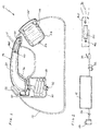
- the portable refreshing device of the present invention indicated as a whole by 10 in Figure 1, comprises a containing unit or reservoir 12, of any shape and size, a small pump 14, for instance of the bellows-type, integrated in said reservoir, and a handle or grip 16 connected through a tube 18 to said reservoir and incorporating a plurality a ducts that flow at the front end in as many supplying nozzles, which will be described later on.
- a cavity 20 is formed that communicates with the outside through a hole closed by a plug 22.
- Reservoir 12 made, for instance, from rigid plastic or plasticized fabric, is intended for containing ambient air which is slightly compressed by a manual action exercised on pump 14 of a substantially known type.
- reservoir 12 has a first recess or shaped seat 24 having a shape entirely complementary to that of the pump 14 that abuts in the same and is stabilized with known means, for instance, adhesives, the upper front of pump 14 is defined by the conventional elastic membrane, indicated by 14', which is hand-compressed in order to pressurize the air in reservoir 12; by way of orientation, the pressures realized in said reservoir is comprised between 0.2 and 1.5 bar.
- an unidirectional valve 26 is located that prevents air from downflowing from reservoir 12.
- a second recess or shaped seat 30 is formed, whose mouth is oriented towards the upper part of said reservoir; said second shaped seat 30, having by way of example a circular plan, constitutes the housing seat of tube 18, advantageously of the coiled type, that causes reservoir 12 to get in touch with handle or grip 16.
- a nonreturn valve 32 is preferably located in correspondence of the end of tube 18, directed to reservoir 12; tube 18 is respectively fastened to the base of the second recess 30 and grip 16 by means of conventional quick attachments or like means.
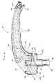
- Said grip advantageously made from plastic material, has in the preferred embodiment a "spout" conformation, made up by two complementary and specular half-shells connected with one another by heat welding, ultrasound welding or like systems.
- the base of grip 16 i.e. the part that connects with tube 18, has an integral tang 34 for the clutch of said tube; in axial alignment with tang 34, a cylindrical seat 44 is formed that develops in the grip and houses an unidirectional valve 46 elastically tensioned by a helical spring 48.
- Said valve 46 is so shaped as to be localizable along a seat 46', preferably conical, that forms a choke 50 in seat 44.
- the upper part of the latter opposed to tang 34 is provided with at least a through-opening 50', radially developed, that causes said seat to get in communication with cavity 20 of grip 16.
- Opening(s) 50' is obtained over seat 46' of valve 46.
- Choke 50 in its lower part facing tube 18, is preferably conified in the same way as seat 46' and forms a mouth interceptable by the shaped end 52 of an operating lever 36, hand-actionable and having its fulcrum on the body of grip 16.
- Lever 36 comes out from the latter through an opening 52', circumscribed by a gasket 53 of the O-ring type or the like.
- Cavity 20 of grip 16 is suitable to receive the liquid, typically water, let in starting from the mouth shielded by plug 22; by way of indication, said cavity is so sized as to contain an amount of liquid comprised between 0.10 and 0.30 liters.
- a duct 42 comes out, integral with grip 16, which branches into at least two tubes 42', developed in a mutually opposed direction throughout the extension of grip 16, in the inside thereof. Tubes 42', opposed to each other, end at the front end of said grip and in such position they bear a conventional supply nozzle whose flow is adjustable and preferably orientable.
- a holed diaphragm 40 possibly shielded by a unidirectional valve 40', which intercepts or open the passage of the liquid present in cavity 20.
- grip 16 Downstream of said diaphragm 40, grip 16 has an additional supply nozzle, indicated by 70, which is advantageously located in an intermediate position with respect to the other two nozzles located at the front end of tubes 42' at the outlet from grip 16.
- the mouth of the second shaped seat 30 is provided with a projection or serration 60, to hook to reservoir 12 the rear part of grip 16, which in the opposite front part is housed along a flat zone 62 created on the same reservoir, extended in an extension 64 which constitutes the fitting-insertion seat of said front part of said grip.
- the latter housed in said seats, advantageously constitutes also the gripping means to transport the device as a whole, reservoir included, when it is not utilized.
- tube 18 can come out extending into the second cavity 30 and therefore said grip 16 can be oriented in the space to be led close to the body part to be refreshed.
- cavity 20 is filled entirely or partly with water, previously let in through the hole closed by plug 22, the only operation to be made by the user is the activation with some impulses of membrane 14' of pump 14, to create in the inside of reservoir 12, which contains only water, a pressure slightly higher than the ambient or environment one.
- the device object of the invention can operate by acting on lever 36. This handling causes the downwards shifting of the shaped end 52 of lever 36, and the pressurized air present in reservoir 12 can therefore flow into seat 44, into choke 50, and from here into the fluid-containing cavity 20.
- the ensuing refreshing effect is, from the one hand, effective, but does not cause, on the other hand, the distribution of excessive amounts of liquid on the skin.
- the device can work continuously provided there is an even minimum amount of liquid in cavity 20, as the user has the possibility of activating repeatedly or at intervals with one hand membrane 14' of pump 14 and with the other hand lever 36, connected to grip 16.
- the device of the present invention allows to obtain an immediate refreshing effect along body zones, and, given its structural configuration, it can be easily utilized in many situations, not necessarily referred to those of typical relax in open and sunny, or in any case hot, spaces.
- Such a device in fact, may be easily transported and used, if needed, in other environments, for instance in cars or campers during travels, without the need of unavoidable stops.
- the only requirement is the availability of a minimum amount of liquid, typically water, in cavity 20 of grip 16.
- Reservoir 12 may be obtained from a flexible material, which further reduces the overall size, moreover already limited, while the global weight of said device, that does not require high amounts of liquid to be let in the reservoir, is negligible.
- the supply ducts of exiting air which invests the drop or drops of liquid to create the micro-mist, may be present in a higher number or have a location different from what has been described and illustrate by way of example; alternatively, thanks to the central duct from which the drop or drops of liquid exit, one only external annular duct for air inlet may be provided, with a suitable configuration of the outlet mouth to orient and concentrate the air flow in the direction of the nozzle from which the liquid comes out.
Landscapes
- Health & Medical Sciences (AREA)
- Public Health (AREA)
- Epidemiology (AREA)
- Pain & Pain Management (AREA)
- Physical Education & Sports Medicine (AREA)
- Rehabilitation Therapy (AREA)
- Life Sciences & Earth Sciences (AREA)
- Animal Behavior & Ethology (AREA)
- General Health & Medical Sciences (AREA)
- Veterinary Medicine (AREA)
- Containers And Packaging Bodies Having A Special Means To Remove Contents (AREA)
Priority Applications (3)
| Application Number | Priority Date | Filing Date | Title |
|---|---|---|---|
| EP01115167A EP1270084A1 (fr) | 2001-06-22 | 2001-06-22 | Dispositif portatif de refroidissement par brouillard pulverisé |
| AU2002347433A AU2002347433A1 (en) | 2001-06-22 | 2002-06-18 | Portable hand-operated cooling device |
| PCT/IB2002/004692 WO2003013735A2 (fr) | 2001-06-22 | 2002-06-18 | Dispositif de rafraichissement portatif a commande manuelle |
Applications Claiming Priority (1)
| Application Number | Priority Date | Filing Date | Title |
|---|---|---|---|
| EP01115167A EP1270084A1 (fr) | 2001-06-22 | 2001-06-22 | Dispositif portatif de refroidissement par brouillard pulverisé |
Publications (1)
| Publication Number | Publication Date |
|---|---|
| EP1270084A1 true EP1270084A1 (fr) | 2003-01-02 |
Family
ID=8177790
Family Applications (1)
| Application Number | Title | Priority Date | Filing Date |
|---|---|---|---|
| EP01115167A Withdrawn EP1270084A1 (fr) | 2001-06-22 | 2001-06-22 | Dispositif portatif de refroidissement par brouillard pulverisé |
Country Status (1)
| Country | Link |
|---|---|
| EP (1) | EP1270084A1 (fr) |
Citations (4)
| Publication number | Priority date | Publication date | Assignee | Title |
|---|---|---|---|---|
| WO1996011748A1 (fr) * | 1994-10-18 | 1996-04-25 | Utter Steven M | Dispositif portatif de refroidissement par brouillard pulverise |
| US5535951A (en) * | 1989-07-06 | 1996-07-16 | Utter; Steven | Misting apparatus |
| GB2309921A (en) * | 1996-02-06 | 1997-08-13 | Marion Bethune Maclennan | Portable microshower |
| US6095434A (en) * | 1997-10-08 | 2000-08-01 | Arizona Mist, Inc. | Portable automatic misting device |
-
2001
- 2001-06-22 EP EP01115167A patent/EP1270084A1/fr not_active Withdrawn
Patent Citations (4)
| Publication number | Priority date | Publication date | Assignee | Title |
|---|---|---|---|---|
| US5535951A (en) * | 1989-07-06 | 1996-07-16 | Utter; Steven | Misting apparatus |
| WO1996011748A1 (fr) * | 1994-10-18 | 1996-04-25 | Utter Steven M | Dispositif portatif de refroidissement par brouillard pulverise |
| GB2309921A (en) * | 1996-02-06 | 1997-08-13 | Marion Bethune Maclennan | Portable microshower |
| US6095434A (en) * | 1997-10-08 | 2000-08-01 | Arizona Mist, Inc. | Portable automatic misting device |
Similar Documents
| Publication | Publication Date | Title |
|---|---|---|
| AU650217B2 (en) | Foam dispensing device | |
| US7051959B2 (en) | Multi-purpose hand held sprayer having a vertical shut-off valve | |
| US7905429B2 (en) | Dispensing system and method for shower arm | |
| US7841494B2 (en) | Pump dispenser | |
| US7243860B2 (en) | Portable misting device with drinking spout and fan assist | |
| AU2002237795B2 (en) | Multiple function dispenser | |
| US10870121B2 (en) | Pressurizable fluid container apparatus | |
| AU2005262832B2 (en) | Vented dispenser | |
| US7131558B2 (en) | Pressure sprayer | |
| WO2004048211A2 (fr) | Dispositif de pressurisation destine a etre fixe a des contenants de fluide | |
| PL184482B1 (pl) | Urządzenie rozpylające | |
| WO2005009808A2 (fr) | Dispositif de lavage de voiture | |
| US5799873A (en) | Portable multi-port liquid dispensing system | |
| US20160175866A1 (en) | Hydration system accessory device | |
| US6561439B1 (en) | Dual closure nozzle | |
| US5082185A (en) | Spray wand without liquid leakage | |
| EP1270084A1 (fr) | Dispositif portatif de refroidissement par brouillard pulverisé | |
| US6095434A (en) | Portable automatic misting device | |
| US9924781B2 (en) | Hydration system accessory device | |
| US12440857B2 (en) | Pressurizable fluid container apparatus | |
| US20010004091A1 (en) | Portable automatic misting device | |
| CA2501687A1 (fr) | Appareil de pulverisation d'un liquide de decontamination | |
| US10632483B1 (en) | Universal pressurized spray adapter | |
| US20150014350A1 (en) | Pressurizable Fluid Container Apparatus | |
| WO2003013735A2 (fr) | Dispositif de rafraichissement portatif a commande manuelle |
Legal Events
| Date | Code | Title | Description |
|---|---|---|---|
| PUAI | Public reference made under article 153(3) epc to a published international application that has entered the european phase |
Free format text: ORIGINAL CODE: 0009012 |
|
| AK | Designated contracting states |
Kind code of ref document: A1 Designated state(s): AT BE CH CY DE DK ES FI FR GB GR IE IT LI LU MC NL PT SE TR |
|
| AX | Request for extension of the european patent |
Free format text: AL;LT;LV;MK;RO;SI |
|
| AKX | Designation fees paid |
Designated state(s): AT BE CH CY DE DK ES FI FR GB GR IE IT LI LU MC NL PT SE TR |
|
| STAA | Information on the status of an ep patent application or granted ep patent |
Free format text: STATUS: THE APPLICATION IS DEEMED TO BE WITHDRAWN |
|
| 18D | Application deemed to be withdrawn |
Effective date: 20030703 |