EP1270096A2 - Reinigungsvorrichtung zum Reinigen eines Hohlraumes - Google Patents
Reinigungsvorrichtung zum Reinigen eines Hohlraumes Download PDFInfo
- Publication number
- EP1270096A2 EP1270096A2 EP02008350A EP02008350A EP1270096A2 EP 1270096 A2 EP1270096 A2 EP 1270096A2 EP 02008350 A EP02008350 A EP 02008350A EP 02008350 A EP02008350 A EP 02008350A EP 1270096 A2 EP1270096 A2 EP 1270096A2
- Authority
- EP
- European Patent Office
- Prior art keywords
- cleaning
- cleaning device
- cleaned
- cavity
- cleaner
- Prior art date
- Legal status (The legal status is an assumption and is not a legal conclusion. Google has not performed a legal analysis and makes no representation as to the accuracy of the status listed.)
- Withdrawn
Links
- 238000004140 cleaning Methods 0.000 title claims abstract description 144
- 239000007921 spray Substances 0.000 claims description 35
- 238000000034 method Methods 0.000 claims description 23
- XLYOFNOQVPJJNP-UHFFFAOYSA-N water Substances O XLYOFNOQVPJJNP-UHFFFAOYSA-N 0.000 claims description 22
- 239000007788 liquid Substances 0.000 claims description 19
- 238000009826 distribution Methods 0.000 claims description 8
- 239000013505 freshwater Substances 0.000 claims description 8
- 238000010438 heat treatment Methods 0.000 claims description 8
- 230000005540 biological transmission Effects 0.000 claims description 7
- 239000012459 cleaning agent Substances 0.000 claims description 6
- 230000008878 coupling Effects 0.000 claims description 6
- 238000010168 coupling process Methods 0.000 claims description 6
- 238000005859 coupling reaction Methods 0.000 claims description 6
- 238000006243 chemical reaction Methods 0.000 claims description 5
- 239000002245 particle Substances 0.000 claims description 2
- 239000003599 detergent Substances 0.000 description 8
- 230000001681 protective effect Effects 0.000 description 6
- 239000000126 substance Substances 0.000 description 5
- 239000000654 additive Substances 0.000 description 4
- 238000013461 design Methods 0.000 description 4
- 230000000996 additive effect Effects 0.000 description 3
- 238000010276 construction Methods 0.000 description 3
- 230000006870 function Effects 0.000 description 3
- 238000003860 storage Methods 0.000 description 3
- 230000015572 biosynthetic process Effects 0.000 description 2
- 238000011109 contamination Methods 0.000 description 2
- 239000012530 fluid Substances 0.000 description 2
- 230000005484 gravity Effects 0.000 description 2
- 238000005507 spraying Methods 0.000 description 2
- 239000000853 adhesive Substances 0.000 description 1
- 230000001070 adhesive effect Effects 0.000 description 1
- 230000009286 beneficial effect Effects 0.000 description 1
- 239000000356 contaminant Substances 0.000 description 1
- 230000003111 delayed effect Effects 0.000 description 1
- 230000001419 dependent effect Effects 0.000 description 1
- 238000011161 development Methods 0.000 description 1
- 230000018109 developmental process Effects 0.000 description 1
- 230000003670 easy-to-clean Effects 0.000 description 1
- 230000007613 environmental effect Effects 0.000 description 1
- 238000011156 evaluation Methods 0.000 description 1
- 238000009434 installation Methods 0.000 description 1
- 230000013011 mating Effects 0.000 description 1
- 238000005457 optimization Methods 0.000 description 1
- 230000009993 protective function Effects 0.000 description 1
- 230000035484 reaction time Effects 0.000 description 1
- 238000012546 transfer Methods 0.000 description 1
Images




Classifications
-
- B—PERFORMING OPERATIONS; TRANSPORTING
- B08—CLEANING
- B08B—CLEANING IN GENERAL; PREVENTION OF FOULING IN GENERAL
- B08B9/00—Cleaning hollow articles by methods or apparatus specially adapted thereto
- B08B9/08—Cleaning containers, e.g. tanks
- B08B9/093—Cleaning containers, e.g. tanks by the force of jets or sprays
-
- F—MECHANICAL ENGINEERING; LIGHTING; HEATING; WEAPONS; BLASTING
- F24—HEATING; RANGES; VENTILATING
- F24C—DOMESTIC STOVES OR RANGES ; DETAILS OF DOMESTIC STOVES OR RANGES, OF GENERAL APPLICATION
- F24C14/00—Stoves or ranges having self-cleaning provisions, e.g. continuous catalytic cleaning or electrostatic cleaning
- F24C14/005—Stoves or ranges having self-cleaning provisions, e.g. continuous catalytic cleaning or electrostatic cleaning using a cleaning liquid
Definitions
- the invention relates to a cleaning device for cleaning of a cavity. Cavities that require intensive cleaning, are particularly in commercial kitchens. In such Commercial kitchens you will find a lot of equipment, such as Large frying appliances, combi ovens and roasting ovens caused by the frying process have high levels of contamination, which are not are easy to clean. Soiling, albeit lighter Kind, are also internal storage spaces, such as interiors of refrigerators and freezers and normal storage cabinets, exposed.
- Hygiene aspects are becoming increasingly important in commercial kitchens and bakeries Play a role and are controlled more and more restrictively, are also in this regard to the kitchen or cleaning staff special requirements. Just cleaning Large roasters require the most intensive of cleaning staff Commitment. The burned-in contaminants are only medium Chemicals, water rinsing and manual cleaning through high cleanse physical exertion. The chemicals that do this used are very aggressive, so the cleaning staff secure by wearing special protective clothing got to.
- the invention has for its object a cleaning device for cleaning a cavity and a method for Operate such to indicate a constantly recurring Cleaning of a plurality of cavities on particular easy to do particularly cheap is.
- a cleaning device for cleaning a cavity wherein in particular to an interior of equipment in a commercial kitchen installation is thought, first means to only temporarily Use of the cleaning device in the cavity and second Means for independently running a cleaning program in the inserted state.
- Such a cleaning device can be used flexibly and enables serial cleaning of cavities by first cleaning them in each Cavity and used to run a cleaning program is put into operation. When the cleaning program is finished, can the cleaning device again from the Cavity are removed, leaving the cavity subsequently can be used again appropriately.
- the first and second means are preferably in a structural unit, in particular one that can be operated alone Cleaning machine, comprising, this unit in the to cleaning cavity can be used for the cleaning process and out of the cavity after the cleaning process is removable.
- the cleaning device preferably has contact surfaces on which with receptacles in the cavity to be cleaned can be associated.
- contact surfaces on which with receptacles in the cavity to be cleaned can be associated.
- Roasting ovens are meant here, slide-in rails that are in the regular Operation of the oven to hold roasting or baking trays or the like.
- These contact surfaces can vary Cavity dimensions can be adjusted accordingly be, that is, the support surfaces are particularly extendable designed.
- the cleaning device is only in one Field of application used in which a standard for cavity dimensions exists, and this standard encompasses several standard dimensions for cavities, it makes sense that the Cleaning device corresponding to each of these standard dimensions includes separate contact surfaces or the contact surfaces be used in any other way. This can be done, for example, by arranging support surfaces done in two different levels.
- a support option another support option by rotating the cleaning device about a quarter turn, which in particular means that the cleaning device is essentially one rectangular projection in terms of their contact surfaces.
- the cleaning device is conveniently constructed by Providing an inner and an outer unit, the outer Unity covers the inner unity and thus from external influences protects.
- the internal unity includes at least a module for operating the cleaning device, the one Protection against environmental influences, especially against chemicals fortified liquids.
- a special design the inner unity sees an upper and a lower functional part before, the upper functional part at least a tank for holding a liquid and the lower one Functional part includes devices for performing the cleaning process.
- This arrangement of the tank above and below lying equipment has the particular advantage that if the tank contents have to be supplied to the equipment, especially a pump, the gravity of the tank contents can be exploited. Thus it can be used as a means of transport a non-self-priming pump for the tank contents as an economical one Alternative can be used.
- the use of a cleaning additive is necessary an appropriate tank to hold this cleaning additive appropriate.
- the cavity should not only be cleaned but also have a clear surface after cleaning, should be both a detergent tank as well as a Rinse aid tank included.
- the cleaning device can be used for the supply for the cleaning process required fresh water with connection means for be equipped with an inlet hose. But should also be closed Cavities are cleaned, it is convenient to the Cleaning device also to hold a water tank Arrange fresh water. This water tank must then of course before each cleaning process, if appropriate, with the appropriate size only before every second or third cleaning process, be filled with fresh water.
- the object to be cleaned can but also a water connection and a supply line own in its cavity to be cleaned. In this Case includes a coupling to the cleaning device.
- One of the slide rails can be part of the equipment internal water supply line of the object to be cleaned be, this rail equipped with the coupling can be. The corresponding mating coupling is then on the Cleaning device on the associated with the slide rail Support area provided.
- the power supply can also be dimensioned accordingly Mains connection cable must be ensured.
- a rechargeable as a power supply Accumulator provided outside of the operating hours of the Cleaning device can be connected to a charging coupling.
- Such an accumulator not only has the advantage that the Cleaning device can also be put into operation if there is no network connection nearby, also delivers such an accumulator only has a voltage in the range of Safety extra-low voltage, so that no special security measures necessary to avoid danger for the operating personnel are.
- At least one particular embodiment of the invention provides one essentially upward and one essentially downward spray nozzle so that a Introducing liquid into the upper part of the cavity and in the lower part of the cavity is possible.
- the at least one upward spray nozzle and the downward spray nozzle or directed Spray nozzles are either common, alternating or each can only be activated. A joint operation of the Spray nozzles allow for faster cleaning during a alternating operation due to the lower liquid transport allows to use weaker transport units.
- a spray nozzle is used, both for a cleaning additive and is suitable for water.
- the respective liquid can then when using suitable reversing means by one and the same Means of transport, that is, by the same pump, the spray nozzle can be supplied, or via separate means of transport feature. Also considered a means of transport for fresh water the water pipe pressure
- Spray nozzles have been implemented. However, preference is only given to one upward and one downward spray nozzle, optionally used with several spray openings, which are rotatable in such a way that each of these two spray nozzles every single point of the upper or lower half space with regard to the respective limiting inner surfaces can operate.
- the cleaning device a control signal to the control device of the to be cleaned Object, again via the information transmission means, sends, whereby the control device of the to be cleaned Object is caused to operate the heating device so that the surface to be cleaned is preheated.
- the cleaning process is facilitated by this heat and cleaning additives can be used that effective only at elevated temperatures, but less aggressive are.
- heating the cleaning surfaces can also be the cleaning liquid be preheated, by providing an appropriate Heating device on the cleaning device should be possible can.
- the object underlying the invention is further achieved by a method for operating the aforementioned cleaning device solved, with a cleaning program at least the cleaning cycles "Cleaner distribution phase", “Cleaner reaction phase” and “water distribution phase”.
- the “cleaner distribution phase” has the task of applying the cleaner to the surface to be cleaned applied. Reacts during the “cleaner reaction phase” the cleaner with those adhering to the surface to be cleaned Parts of dirt so that this contamination is loosened and their intensive adhesive bond to the surface to be cleaned is broken up.
- the "water distribution phase” is fresh water under a not too low spray pressure on the one to be cleaned Sprayed surface so that the dirt and also the Possibly too much applied cleaner from the one to be cleaned Surface is removed. Then you can do a rinse cycle be provided in which with the aid of a rinse aid the surface tension of the cleaning liquid like this is reduced that this on the surfaces to be cleaned runs off completely and no water stains remain.
- the individual Parameters of this cleaning program in particular the duration of the Cleaning cycle, spray pressure to be set and preheating the surface to be cleaned or rinsing liquid, not to be preset, but to make it dependent on the state of pollution.
- the individual parameters can be influenced further also depend on which operating programs the object to be cleaned is processed before the cleaning process Has.
- the Cleaning device other means of transport for liquids include, through which the dirty at the end of the cleaning process Cleaning liquid can be transported into the water tank is. Closed, cleaned cavities can thus largely be freed of the dirty cleaning liquid.
- means of transport for the cleaning device itself for example a chassis with wheels, is conceivable so that a portable use in operation is possible.
- a cleaning device constructed in this way can be used for cleaning Serve sewer pipes.
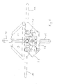
- the cleaning device shown in the figures is flexible in Commercial kitchen appliances, such as baking ovens, combi ovens, convection ovens, Refrigerators, freezers and other cabinet units insertable. For this purpose it is in a first approximation spherical construction shown in vertical projection however with square outer edges.
- the cleaning device points on two opposite sides each a handle 11, these handles 11 not only are suitable for transporting the device, but also beyond serve as support rods, which are to be cleaned in the slide rails Cavity, especially a roasting oven, insertable are.
- These handles 11 are designed so that together with these results in a rectangular outer shape and thus one insert of the cleaning device in two perpendicular to each other standing directions is possible.
- the handles are the norm for bakeries adjustable: 600 x 400 mm.
- the device itself be rotatably arranged.
- the cleaning device is divided into two sections, namely into an outer section and an inner section.
- the outer section essentially comprises a protective cover 1, 3 corresponding to Figure 2.
- This protective cover 1, 3 has a upper cover 1 and a lower cover 3, which have an essentially identical design and only to one another are arranged mirror-symmetrically.
- Each of these covers 1, 3 is laterally bordered by four side walls 5, which uniform, d. H. Axially symmetrical, trapezoidal are.
- the assembly of these four side walls 5 thus results an even truncated pyramid with a square Base area and a square top surface, the latter the upper cover wall 7 (or lower cover wall 9 in the case of lower cover) forms.
- the protective cover 1, 3 has two Functions, namely a design function, but also a protective function for the inner section. Protection against the following working environment can be created: a maximum temperature of approx. 90 ° C, a high humidity of 100% r. F., aggressive chemical substances in cleaning agents.
- this protective cover 1, 3 consists of a temperature-resistant Plastic with extremely high chemical resistance.
- the protective cover 1, 3 encloses the inner section of the cleaning device complete, only in the centers of the top and lower cover walls 7, 9 holes are provided, which serve for the passage of two cleaning nozzles 13, 15, wherein these nozzles 13, 15 are sealed against the bores.
- the inner section of the cleaning device includes all for the Operation required components. This is the inner section divided into two functional parts: an upper functional part for holding two detergent tanks 17, 19, which is approximately within that covered by the upper cover 1 Room is localized, and a lower functional part for the inclusion of other facilities and equipment, this lower functional part in the essentially of the lower Cover 3 protected space is arranged.
- an upper functional part for holding two detergent tanks 17, 19, which is approximately within that covered by the upper cover 1 Room is localized
- a lower functional part for the inclusion of other facilities and equipment, this lower functional part in the essentially of the lower Cover 3 protected space is arranged.
- a pump 21 in the lower functional part which the cleaner stored in the detergent tank 17 and the Rinse aid tank 19 stored rinse aid according to the Specifications of an operating program using pipes 23 den Spray nozzles 13, 15 supplies.
- This particular arrangement of the above lying tanks 17, 19 and the pump 21 arranged underneath offers the advantage that detergent and rinse aid Gravity feed the pump, making it costly self-priming pump can be dispensed with.
- valves 25, 27 are provided which is the access of cleaning fluid from the cleaning tank 17 to pump 21 (valve 25) and rinse aid from the rinse aid tank Release or block 19 to pump 21 (valve 27).
- Valve 27 Of the Pump 21 goes off another pipe 23, which in one another valve 29 opens.
- This valve 29 has an inlet and two exits, the latter each with a spray nozzle 13, 15 are connected.
- Another valve 31 also two outputs, which are connected to the nozzles 13, 15 are, has a water connection on the input side for coupling to a water supply system using a hose on.
- the lower functional part also includes one rechargeable 12 or optionally 24 VDC accumulator and an electronic program control, which from the box 33 are included.
- FIG. 7 shows an individual illustration of the spray nozzles 13, 15.
- These spray nozzles 13, 15 comprise an upper nozzle body 35 and a lower nozzle body 37.
- the upper nozzle body 35 is mounted rotationally symmetrically with respect to the lower nozzle body 37, so that when the lower nozzle body 37 is rigidly installed the upper nozzle body 35 rotates during operation.
- upper nozzle body 35 has an upwardly directed nozzle slot 39 and a nozzle slot 41 directed to the side on.
- the bore in the nozzle slot 41 is arranged so that the escaping liquid is not only discharged radially but has a tangential component. This tangential component causes the drive of the upper nozzle body 35.
- the nozzle slots 39, 41 are designed such that a spherical spray area of 240 ° with one revolution of the upper nozzle body 35 is covered. In this way can be cleaned with the two spray nozzles 13, 15 Cavity to be sprayed.
- the cleaning device described above in the construction is before the start of operation in the cavity to be cleaned, for example inserted into a roasting oven of a commercial kitchen. For this his handles 11 in slide rails of the oven with the insert orientation as described above depend on the dimensions of the oven.
- the present Cleaning device comes with a water supply hose connected or is standard with a water connection equipped, which engages in a water valve built into the device becomes. For this, as already described, on the water inlet valve 31 a corresponding connection piece is provided.
- the cleaning program that is running comprises several cleaning cycles. These cleaning cycles are delayed manually Selector switch selected, e.g. B. Cleaning level 1 (slightly dirty) up to level 4 (very dirty). The time delay enables the cavity to be closed before cleaning begins.
- a preheating phase can be carried out are at the beginning of the operating program.
- the cleaning device can be a not shown Have transmission device, which to a control device of the roasting oven via a receiving device included therein Outputs signal to switch on the heating device of the roasting oven. After a predefined time, a new one Signal the preheating phase leading to an ambient temperature of approx. 45 ° C, ended.
- Valves 25 and 29 opened and the pump 21 briefly in operation set until sufficient cleaning fluid through the Nozzles 13, 15 has been discharged.
- Valve 29 opens the Outputs to the nozzles 13, 15 in series, so that the cleaner first a spray nozzle, in particular the upper spray nozzle 13, and then the other spray nozzle 15 is supplied.
- the cleaner has in the subsequent cleaner reaction phase the opportunity to adhere to the surfaces to be cleaned To loosen dirt particles, the duration of this reaction phase again depends on the type of cleaner used.
- valve 31 is opened, whereby again the outputs to the two spray nozzles alternately 13, 15 can be opened. After a sufficient rinsing phase, the valve 31 closed again.
- valve 27 is first connected to valve 29 opened, with the two outputs again in series at valve 29 can be controlled.
- Pump 21 has as in the case of the cleaning agent the task of rinse aid through the spray nozzles 13, 15 to be applied to the surfaces to be cleaned. Right away after applying the rinse aid, that is after Deactivating the pump 21 and the valves 27 and 29 takes place Another short water entry by opening valve 31 for rinsing and rinsing the surfaces.
- the cleaning device and the cavity to be cleaned can also be designed so that they alternate Exchange information about the cleaning program to optimize. You can either use a roasting oven to be cleaned transmit information about the last cooking program (s).
- the roasting oven can also be equipped with dirt sensors be the degree of pollution of the muffle walls determine and this information in turn via appropriate Hand over the transmission equipment to the cleaning device.
- valves 25, 27, 29, 31, the pump 21 and the control electronics of the cleaning device are enclosed in the box 33 12 or 24 VDC battery powered. This accumulator after the cleaning program and If necessary, remove the cleaning device from an appropriate one Charging station connected. However, preferred an accumulator capacity chosen to run three long or five short cleaning programs for cleaning of several canteen kitchen appliances is sufficient.
Landscapes
- Engineering & Computer Science (AREA)
- Chemical & Material Sciences (AREA)
- Mechanical Engineering (AREA)
- Chemical Kinetics & Catalysis (AREA)
- Combustion & Propulsion (AREA)
- General Engineering & Computer Science (AREA)
- Cleaning By Liquid Or Steam (AREA)
- Cleaning Implements For Floors, Carpets, Furniture, Walls, And The Like (AREA)
Abstract
Description
- Figur 1
- ein Reinigungsgerät zum variablen Einsatz in Großküchen in der Seitenansicht mit durchscheinend dargestellter Abdeckschale;
- Figur 2
- eine Einzeldarstellung der Abdeckschale gemäß Figur 1;
- Figur 3
- eine Draufsicht auf das Reinigungsgerät gemäß Figur 1 bei abgenommener Abdeckschale;
- Figur 4
- eine Ansicht von unten des Reinigungsgerätes gemäß Figur 1 bei abgenommener Abdeckschale;
- Figur 5
- eine Vorderansicht des Reinigungsgerätes gemäß Figur 1 bei abgenommener Abdeckschale;
- Figur 6
- die Seitenansicht gemäß Figur 1 bei abgenommener Abdeckschale; und
- Figur 7
- eine Einzeldarstellung einer Reinigungsdüse des Reinigungsgerätes gemäß Figur 1.
Claims (18)
- Reinigungsvorrichtung zum Reinigen eines Hohlraumes, insbesondere eines Innenraumes einer Großküchen- oder Bäckereianlage, mit ersten Mitteln zum lediglich zeitweisen Einsatz der Reinigungsvorrichtung im Hohlraum und zweiten Mitteln zum selbständigen Ausführen eines Reinigungsprogrammes im eingesetzten Zustand.
- Reinigungsvorrichtung nach Anspruch 1, dadurch gekennzeichnet, dass die ersten und die zweiten Mittel in einer Baueinheit umfasst sind, die in den Hohlraum einsetzbar und diesem nach Ablauf des Reinigungsprogrammes vorzugsweise vollständig entnehmbar ist.
- Reinigungsvorrichtung nach Anspruch 1 oder 2, dadurch gekennzeichnet, dass die ersten Mittel Auflageflächen (11) für Aufnahmevorrichtungen, insbesondere Einschubschienen, im zu reinigenden Hohlraum umfassen, wobei die Auflageflächen (11) vorzugsweise an die Abmessungen des Hohlraumes anpassbar sind.
- Reinigungvorrichtung nach Anspruch 1 oder 2, dadurch gekennzeichnet, dass die ersten Mittel Auflageflächen (11) für Aufnahmevorrichtungen, insbesondere Einschubschienen, im zu reinigenden Hohlraum umfassen, wobei die Hohlraumabmessungen genormt sind und im Falle mehrerer gültiger Normabmessungen für jede dieser Normabmessungen entsprechende Auflageflächen (11) umfasst sind.
- Reinigungsvorrichtung nach Anspruch 4, dadurch gekennzeichnet, dass bei Wirksamsein einer Auflagefläche bzw. einer Gruppe von Auflageflächen (11) durch Drehen der Reinigungsvorrichtung um 90° eine weitere Auflagefläche bzw. eine weitere Gruppe von Auflageflächen wirksam wird, oder die eine Auflagefläche (11) bzw. die eine Gruppe von Auflageflächen (11) auf jeweils unterschiedliche Weise in Benutzung genommen wird bzw. werden.
- Reinigungsvorrichtung nach wenigstens einem der Ansprüche 1 bis 5, dadurch gekennzeichnet, dass eine innere Einheit und eine äußere Einheit umfasst sind, wobei die äußere Einheit eine Abdeckung der inneren Einheit bildet und die innere Einheit wenigstens ein Modul zum Betreiben der Reinigungsvorrichtung umfasst.
- Reinigungsvorrichtung nach Anspruch 6, dadurch gekennzeichnet, dass die innere Einheit ein oberes und ein unteres Funktionsteil aufweist, wobei das obere Funktionsteil wenigstens einen Tank (17, 19) zur Aufnahme einer Flüssigkeit und das untere Funktionsteil Geräte zur Ausführung des Reinigungsvorganges umfasst.
- Reinigungsvorrichtung nach wenigstens einem der Ansprüche 1 bis 7, dadurch gekennzeichnet, dass ein Wassertank zur Aufnahme von Frischwasser, in welchen insbesondere am Ende des Reinigungsvorganges die verschmutzte Reinigungsflüssigkeit transportierbar ist, und/oder wenigstens ein Tank (17, 19) zur Aufnahme wenigstens eines Reinigungsmittels vorgesehen ist, wobei vorzugsweise je ein Tank (17) für ein Reinigungsmittel und ein Tank (19) für ein Klarspülmittel umfasst sind.
- Reinigungsvorrichtung nach wenigstens einem der Ansprüche 1 bis 8, dadurch gekennzeichnet, dass eine Stromversorgung umfasst ist, welche vorzugsweise als ein wieder aufladbarer Akkumulator ausgestaltet ist, der außerhalb der Betriebszeit der Reinigungsvorrichtung an eine Ladekopplung anschließbar ist.
- Reinigungsvorrichtung nach wenigstens einem der Ansprüche 1 bis 9, dadurch gekennzeichnet, dass wenigstens eine Sprühdüse (13, 15) zum Auftragen von Flüssigkeit auf die zu reinigenden Oberflächen umfasst ist, welche vorzugsweise wenigstens eine im Wesentlichen nach oben gerichtete (13) und eine im Wesentlichen nach unten gerichtete (15) Sprühdüse umfasst sind und die nach.oben gerichtete Düse (13) bzw. die nach oben gerichteten Düsen und die nach unten gerichtete Düse (15) bzw. die nach unten gerichteten Düsen gemeinsam, alternierend oder ausschließlich aktivierbar ist bzw. sind.
- Reinigungsvorrichtung nach Anspruch 10, dadurch gekennzeichnet, dass die wenigstens eine Sprühdüse (13, 15) sowohl für ein Reinigungsmittel als auch für Wasser einsetzbar ist.
- Reinigungsvorrichtung nach Anspruch 10 oder 11, dadurch gekennzeichnet, dass die wenigstens eine Sprühdüse (13, 15) derart rotierbar ist, dass durch die eine Sprühdüse (13, 15) bzw. durch die Gesamtheit der Sprühdüsen jeder Punkt der zu reinigenden Oberfläche ansprühbar ist.
- Reinigungsvorrichtung nach wenigstens einem der Ansprüche 1 bis 12, dadurch gekennzeichnet, dass ein Informationsübertragungsmittel vorgesehen ist, das mit einem zweiten Informationsübertragungsmittel am zu reinigenden Objekt korrespondiert, wodurch Information vom zu reinigenden Objekt zum Zwecke der Optimierung des Reinigungsvorganges einholbar ist und/oder Steuersignale von der Reinigungsvorrichtung zum zu reinigenden Objekt übertragbar sind, wobei insbesondere am zu reinigenden Objekt ein Schmutzsensor angeordnet ist.
- Reinigungsvorrichtung nach wenigstens einem der Ansprüche 1 oder 2 oder 6 bis 13, dadurch gekennzeichnet, dass Fortbewegungsmittel umfasst sind, durch die ein ortsveränderlicher Einsatz der Reinigungsvorrichtung im Betrieb ermöglicht ist.
- Verfahren zum Betreiben einer Reinigungsvorrichtung nach wenigstens einem der Ansprüche 1 bis 14, dadurch gekennzeichnet, dass wenigstens folgende Reinigungszyklen umfasst sind:a) Reiniger-Verteilphase zum Aufbringen des Reinigers auf die zu reinigende Oberflächeb) Reiniger-Reaktionsphase zum Reagieren des Reinigers mit den an der zu reinigenden Oberfläche anhaftenden Schmutzteilenc) Wasser-Verteilphase zum Entfernen des Reinigers und des Schmutzes von der zu reinigenden Oberfläche.
- Verfahren nach Anspruch 15, dadurch gekennzeichnet, dass eine Vorheizphase zu Beginn der Reinigungsphase vorgesehen ist, wobei insbesondere die zu reinigende Oberfläche und/oder das Reinigungsmittel vorgeheizt wird.
- Verfahren nach wenigstens einem der Ansprüche 15 oder 16, dadurch gekennzeichnet, dass ein Steuersignal von der Reinigungsvorrichtung zum zu reinigenden Objekt über je ein Informationsübertragungssignal an der Reinigungsvorrichtung und am zu reinigenden Objekt gesandt wird, wodurch eine Steuereinrichtung am zu reinigenden Objekt eine Heizeinrichtung zur Beheizung der zu reinigenden Oberfläche einschaltet.
- Verfahren nach wenigstens einem der Ansprüche 15 bis 17, dadurch gekennzeichnet, dass die einzelnen Parameter des Reinigungsprogrammes in Abhängigkeit des Verschmutzungszustandes und/oder der einzelnen, dem Reinigungsvorgang vorangegangenen Betriebsprogramme des zu reinigenden Objektes eingestellt werden.
Applications Claiming Priority (2)
| Application Number | Priority Date | Filing Date | Title |
|---|---|---|---|
| DE2001129460 DE10129460A1 (de) | 2001-06-19 | 2001-06-19 | Reinigungsvorrichtung zum Reinigen eines Hohlraumes |
| DE10129460 | 2001-06-19 |
Publications (2)
| Publication Number | Publication Date |
|---|---|
| EP1270096A2 true EP1270096A2 (de) | 2003-01-02 |
| EP1270096A3 EP1270096A3 (de) | 2004-01-28 |
Family
ID=7688643
Family Applications (1)
| Application Number | Title | Priority Date | Filing Date |
|---|---|---|---|
| EP02008350A Withdrawn EP1270096A3 (de) | 2001-06-19 | 2002-04-12 | Reinigungsvorrichtung zum Reinigen eines Hohlraumes |
Country Status (2)
| Country | Link |
|---|---|
| EP (1) | EP1270096A3 (de) |
| DE (1) | DE10129460A1 (de) |
Cited By (1)
| Publication number | Priority date | Publication date | Assignee | Title |
|---|---|---|---|---|
| WO2016059129A3 (de) * | 2014-10-17 | 2016-06-09 | Guggenberger Reinigungstechnik E.K | Verfahren und vorrichtung für die backofenreinigung |
Family Cites Families (10)
| Publication number | Priority date | Publication date | Assignee | Title |
|---|---|---|---|---|
| DE2453673B2 (de) * | 1974-11-13 | 1977-10-20 | Beyer, Paul, 7151 Nellmersbach | Keimkasten zum keimen und ausweichen von maelzgut auf durchlaessigen hordenboeden |
| DE2538591C3 (de) * | 1975-08-29 | 1981-10-08 | Alan D. Los Angeles Calif. Brite | Vorrichtung zum Aufbringen eines Reinigungsmittels auf Innenwände von Küchenherden o.dgl. |
| US4141374A (en) * | 1976-06-16 | 1979-02-27 | Wash Wagon Corporation | Trailer washing apparatus |
| DE2842771A1 (de) * | 1978-09-30 | 1980-04-10 | Lechmetall Landsberg Gmbh | Vorrichtung und verfahren zur waermebehandlung von nahrungsmitteln, insbesondere zur zubereitung von speisen |
| SE500131C2 (sv) * | 1992-10-14 | 1994-04-25 | Jansson N E Konsultfirma Ab | Anordning för invändig rengöring av en kanal |
| US5640982A (en) * | 1994-11-18 | 1997-06-24 | Landry Service Co. Inc. | Tank cleaning system using collapsible robotic tank entry vehicle |
| DE19614439A1 (de) * | 1996-04-12 | 1997-10-16 | Wiesheu Wiwa Gmbh | Ofen und Verfahren zur Reinigung eines Ofenraums |
| DE19817504A1 (de) * | 1998-04-20 | 1999-10-28 | Krause Biagosch Gmbh | Einrichtung zur Reinigung der Herdplatte in Backöfen |
| SE518392C2 (sv) * | 1998-12-22 | 2002-10-01 | Jan Sandberg | Metod för rengöring av djurstallar med en automatisk rengöringsanordning samt automatisk rengöringsanordning |
| DE29913995U1 (de) * | 1999-08-11 | 2000-12-28 | Wap Reinigungssysteme Gmbh & Co, 89287 Bellenberg | Backofendüse mit Schabeleiste |
-
2001
- 2001-06-19 DE DE2001129460 patent/DE10129460A1/de not_active Withdrawn
-
2002
- 2002-04-12 EP EP02008350A patent/EP1270096A3/de not_active Withdrawn
Cited By (1)
| Publication number | Priority date | Publication date | Assignee | Title |
|---|---|---|---|---|
| WO2016059129A3 (de) * | 2014-10-17 | 2016-06-09 | Guggenberger Reinigungstechnik E.K | Verfahren und vorrichtung für die backofenreinigung |
Also Published As
| Publication number | Publication date |
|---|---|
| DE10129460A1 (de) | 2003-03-20 |
| EP1270096A3 (de) | 2004-01-28 |
Similar Documents
| Publication | Publication Date | Title |
|---|---|---|
| EP3418005B1 (de) | System aus mindestens einem haushaltsgerät, mindestens einem sich selbsttätig fortbewegenden reinigungsgerät und einer steuereinrichtung | |
| DE10109247B4 (de) | Vorrichtung und Verfahren zur Reinigung eines Gargerätes | |
| EP2724082B1 (de) | Gargerät mit einem tiegel und verfahren zur reinigung des tiegels | |
| EP3581083B1 (de) | Reinigungssystem, umfassend versorgungsroboter und reinigungssatelliten, und verfahren zur reinigung | |
| DE102007052067A1 (de) | Reinigungsvorrichtung zur Reinigung von Spritzpistolen | |
| DE3722282C2 (de) | ||
| DE102007004599B4 (de) | Hauben-Geschirrspülmaschine mit Kondensatniederschlagseinrichtung | |
| WO1994005197A1 (de) | Aufbewahrungs- und wartungseinrichtung | |
| DE102010017177A1 (de) | Einrichtung zur Wärmebehandlung von Lebensmitteln | |
| WO2016059129A2 (de) | Verfahren und vorrichtung für die backofenreinigung | |
| DE202010005532U1 (de) | Einrichtung zur Wärmebehandlung von Lebensmitteln | |
| EP1270096A2 (de) | Reinigungsvorrichtung zum Reinigen eines Hohlraumes | |
| EP2867585B1 (de) | Verfahren zum betreiben einer abluftanlage und abluftanlage für eine küche | |
| EP2559495B1 (de) | Vorrichtung zum Reinigen von Schusswaffen mittels Ultraschall | |
| DE102021215107B3 (de) | Automatisierte Kochstation und Verfahren zum automatisierten Kochen | |
| EP2611552B1 (de) | Mobiles reinigungssystem | |
| DE102017109696B4 (de) | Reinigungsvorrichtung für Malerwerkzeug | |
| WO2005044473A1 (de) | Vorrichtung zum reinigen von stapelbaren erzeugnissen | |
| EP3927222B1 (de) | Spülsystem zur reinigung von reinigungsgut mit mindestens einem hohlraum | |
| DE102009005350A1 (de) | Waschgerät | |
| DE202011000154U1 (de) | Verbessertes Gerät für die Zubereitung von Nahrungsmitteln | |
| DE102015114006B4 (de) | Backofenreinigungssystem und -verfahren | |
| EP0770432B1 (de) | Waschmaschine | |
| EP2564945A2 (de) | Waschanlage zum Reinigen von insbesondere sperrigem Spülgut | |
| WO2021018612A1 (de) | Haushalts-geschirrspülmaschine |
Legal Events
| Date | Code | Title | Description |
|---|---|---|---|
| PUAI | Public reference made under article 153(3) epc to a published international application that has entered the european phase |
Free format text: ORIGINAL CODE: 0009012 |
|
| AK | Designated contracting states |
Kind code of ref document: A2 Designated state(s): AT BE CH CY DE DK ES FI FR GB GR IE IT LI LU MC NL PT SE TR |
|
| AX | Request for extension of the european patent |
Free format text: AL;LT;LV;MK;RO;SI |
|
| PUAL | Search report despatched |
Free format text: ORIGINAL CODE: 0009013 |
|
| AK | Designated contracting states |
Kind code of ref document: A3 Designated state(s): AT BE CH CY DE DK ES FI FR GB GR IE IT LI LU MC NL PT SE TR |
|
| AX | Request for extension of the european patent |
Extension state: AL LT LV MK RO SI |
|
| 17P | Request for examination filed |
Effective date: 20040726 |
|
| AKX | Designation fees paid |
Designated state(s): AT BE CH CY DE DK ES FI FR GB GR IE IT LI LU MC NL PT SE TR |
|
| 17Q | First examination report despatched |
Effective date: 20050817 |
|
| STAA | Information on the status of an ep patent application or granted ep patent |
Free format text: STATUS: THE APPLICATION IS DEEMED TO BE WITHDRAWN |
|
| 18D | Application deemed to be withdrawn |
Effective date: 20070801 |