EP1270098A2 - Verfahren zur Herstellung einer Schutzhülle für ein Zerkleinerungsgerät, und dieses Zerkleinerungsgerät - Google Patents
Verfahren zur Herstellung einer Schutzhülle für ein Zerkleinerungsgerät, und dieses Zerkleinerungsgerät Download PDFInfo
- Publication number
- EP1270098A2 EP1270098A2 EP02100575A EP02100575A EP1270098A2 EP 1270098 A2 EP1270098 A2 EP 1270098A2 EP 02100575 A EP02100575 A EP 02100575A EP 02100575 A EP02100575 A EP 02100575A EP 1270098 A2 EP1270098 A2 EP 1270098A2
- Authority
- EP
- European Patent Office
- Prior art keywords
- protective cover
- cover
- cover parts
- parts
- tool
- Prior art date
- Legal status (The legal status is an assumption and is not a legal conclusion. Google has not performed a legal analysis and makes no representation as to the accuracy of the status listed.)
- Withdrawn
Links
Images



Classifications
-
- E—FIXED CONSTRUCTIONS
- E02—HYDRAULIC ENGINEERING; FOUNDATIONS; SOIL SHIFTING
- E02F—DREDGING; SOIL-SHIFTING
- E02F3/00—Dredgers; Soil-shifting machines
- E02F3/04—Dredgers; Soil-shifting machines mechanically-driven
- E02F3/96—Dredgers; Soil-shifting machines mechanically-driven with arrangements for alternate or simultaneous use of different digging elements
- E02F3/966—Dredgers; Soil-shifting machines mechanically-driven with arrangements for alternate or simultaneous use of different digging elements of hammer-type tools
-
- B—PERFORMING OPERATIONS; TRANSPORTING
- B21—MECHANICAL METAL-WORKING WITHOUT ESSENTIALLY REMOVING MATERIAL; PUNCHING METAL
- B21C—MANUFACTURE OF METAL SHEETS, WIRE, RODS, TUBES, PROFILES OR LIKE SEMI-MANUFACTURED PRODUCTS OTHERWISE THAN BY ROLLING; AUXILIARY OPERATIONS USED IN CONNECTION WITH METAL-WORKING WITHOUT ESSENTIALLY REMOVING MATERIAL
- B21C37/00—Manufacture of metal sheets, rods, wire, tubes, profiles or like semi-manufactured products, not otherwise provided for; Manufacture of tubes of special shape
- B21C37/06—Manufacture of metal sheets, rods, wire, tubes, profiles or like semi-manufactured products, not otherwise provided for; Manufacture of tubes of special shape of tubes or metal hoses; Combined procedures for making tubes, e.g. for making multi-wall tubes
- B21C37/08—Making tubes with welded or soldered seams
- B21C37/0803—Making tubes with welded or soldered seams the tubes having a special shape, e.g. polygonal tubes
-
- Y—GENERAL TAGGING OF NEW TECHNOLOGICAL DEVELOPMENTS; GENERAL TAGGING OF CROSS-SECTIONAL TECHNOLOGIES SPANNING OVER SEVERAL SECTIONS OF THE IPC; TECHNICAL SUBJECTS COVERED BY FORMER USPC CROSS-REFERENCE ART COLLECTIONS [XRACs] AND DIGESTS
- Y10—TECHNICAL SUBJECTS COVERED BY FORMER USPC
- Y10T—TECHNICAL SUBJECTS COVERED BY FORMER US CLASSIFICATION
- Y10T225/00—Severing by tearing or breaking
- Y10T225/10—Methods
- Y10T225/12—With preliminary weakening
-
- Y—GENERAL TAGGING OF NEW TECHNOLOGICAL DEVELOPMENTS; GENERAL TAGGING OF CROSS-SECTIONAL TECHNOLOGIES SPANNING OVER SEVERAL SECTIONS OF THE IPC; TECHNICAL SUBJECTS COVERED BY FORMER USPC CROSS-REFERENCE ART COLLECTIONS [XRACs] AND DIGESTS
- Y10—TECHNICAL SUBJECTS COVERED BY FORMER USPC
- Y10T—TECHNICAL SUBJECTS COVERED BY FORMER US CLASSIFICATION
- Y10T225/00—Severing by tearing or breaking
- Y10T225/30—Breaking or tearing apparatus
-
- Y—GENERAL TAGGING OF NEW TECHNOLOGICAL DEVELOPMENTS; GENERAL TAGGING OF CROSS-SECTIONAL TECHNOLOGIES SPANNING OVER SEVERAL SECTIONS OF THE IPC; TECHNICAL SUBJECTS COVERED BY FORMER USPC CROSS-REFERENCE ART COLLECTIONS [XRACs] AND DIGESTS
- Y10—TECHNICAL SUBJECTS COVERED BY FORMER USPC
- Y10T—TECHNICAL SUBJECTS COVERED BY FORMER US CLASSIFICATION
- Y10T225/00—Severing by tearing or breaking
- Y10T225/30—Breaking or tearing apparatus
- Y10T225/371—Movable breaking tool
Definitions
- the invention relates to a method for manufacturing a protective cover for a breaking apparatus, the breaking apparatus comprising a percussion device having a percussion piston arranged to make reciprocating motion in the axial direction and to strike a strike-receiving surface of a tool on the axial extension of the percussion piston for providing an impact impulse in the tool, whereby the tool transmits the impact impulse further to a target to be treated, the breaking apparatus also comprising a protective cover, within which the percussion device is arranged, and the method comprising the following steps: forming two elongated cover parts, arranging longitudinal edge portions of the cover parts substantially against each other in order to achieve a tubular structure having a substantially rectangular cross section, arranging a transverse upper piece at the upper end of the protective cover, and also arranging a transverse lower piece at the lower end of the protective cover, through which the tool is directed.
- the invention also relates to a breaking apparatus comprising a percussion device having a percussion piston arranged to make reciprocating motion in the axial direction and to strike a strike-receiving surface of a tool on the axial extension of the percussion piston for providing an impact impulse in the tool, whereby the tool transmits the impact impulse further to a target to be treated
- the breaking apparatus also comprising a protective cover, within which the percussion device is arranged, and the protective cover is formed of two elongated cover parts comprising longitudinal edges, and the cover parts are fastened together from the longitudinal edges thereof to form a tubular structure having a substantially rectangular cross section, and the protective cover also comprises a transverse upper piece at the upper end of the protective cover and correspondingly a transverse lower piece at the lower end of the protective cover, through which the tool is arranged.
- Breaking apparatuses or percussion hammers, are used for breaking stone, concrete, asphalt, frozen ground, metal slag and other relatively hard materials.
- the percussion hammers are mounted to replace excavator buckets, and consequently they are operated by excavator hydraulics.
- Other basic machines and carriers can be used as well.
- the breaking apparatus comprises a percussion device, to which a tool is attached.
- a percussion piston of the percussion device moves to and fro by impact of pressure medium, strikes a strike-receiving surface of the tool and provides an impact impulse in the tool.
- the tool is simultaneously pressed against the target to be treated, whereby the tool penetrates, by the effect of the impact, into the material to be treated and makes the material break or cut, depending on the shape of the tool.
- the structure of a breaking apparatus generally comprises a protective cover, within which the percussion device is arranged.
- the primary object of a protective cover is to protect the percussion device from dents and impurities.
- a known protective cover comprises two elongated halves having U-shaped cross-sections and bent of plate material. In this assembly the longitudinal edges of the halves are arranged end to end against each other and joined with a welded joint to form a uniform tubular structure.
- the protective cover must therefore be machined after assembly, so that the mounting faces, which are accurate enough, are provided inside the protective cover for mounting the percussion device.
- the plate materials of the halves must be dimensioned to be fairly thick in order to be provided with the required allowance for machining. In brief, the protective cover is heavy and expensive to manufacture.
- Another known protective cover is composed of four platelike sideportions, which are rectangularly positioned and welded together from the longitudinal edges thereof to form a tubular structure.
- This solution comprises a number of welded joints and the assembly is difficult, and the protective cover is therefore slow and expensive to manufacture.
- the structure is provided with several welded joints, dimensional and form errors caused by heat expansion are created thereto during assembly. Hence, this protective cover must also typically be machined after assembly.
- the protective cover In both solutions described above the protective cover must be machined after assembly, a fact that has to be taken into account already when the structure of the protective cover is designed. It is therefore typical to form the protective cover in the longitudinal direction of two parts, i.e. of an upper and a lower part, into which parts the required mounting faces are easier to machine. After machining, the upper and lower parts are joined together using a transverse welded joint in the protective cover.
- Such a structure comprises a particularly large number of welded joints and working stages, and is therefore laborious and expensive to manufacture.
- a protective cover comprising several joints is liable to shredding.
- the method of the invention is characterized by forming two cover parts having a substantially L-shaped cross section, adjusting the mutual position of the cover parts in the transverse direction in order to achieve the designed inner dimensions of the protective cover and fastening the cover parts within the area of the longitudinal edges immovably to one another after the adjusting measures have been taken.
- the breaking apparatus of the invention is characterized in that the cross section of the cover parts is substantially L-shaped.
- the protective cover is formed of two elongated cover parts having a substantially L-shaped cross section, which are joined together to form a tubular structure having a rectangular cross section.
- the form and dimensions of the protective cover in cross section can be adjusted during assembly by moving the cover parts transversely in relation to one another.
- the L-shaped cover parts allow adjusting the cross section of the protective cover in two directions perpendicular to one another, i.e. in the vertical and horizontal direction of the rectangle. After adjusting the designed dimensions and form to the cross section of the protective cover, the cover parts are immovably joined together, for example by welding.
- An advantage with the method of the invention is that in order to ensure the cross sectional dimensions of the protective cover, the protective cover does no longer have to be machined after assembly, instead the cross section profile of the protective cover, i.e. the dimensions and form, can already during assembly be adjusted to be accurate enough. The possible inaccuracies that have occurred during the manufacture of the cover parts can thus be compensated. Since an expensive machining stage is left out, the manufacturing costs of the protective cover are lower than before.
- the protective cover can be designed more freely than before, as the machining stage after assembly need not be taken into account in the structure of the protective cover.
- Another advantage is that the protective cover can be made of a thinner plate material than before, which also makes the protective cover easier to manufacture as well as lighter.
- the L-shape of the cover parts in the protective cover according to the invention allows the welded joints to be placed in the corners of the protective cover, whereby each side of the protective cover is uniform and even. Furthermore, as the joints are placed in the stiff corners of the protective cover, they resist wear far better than the covers formed of U-shaped cover parts, in which the joints are placed in the middle of the cover side.
- An essential idea of an embodiment of the invention is that at least one of the longitudinal joint edges of the cover parts arranged against one another is bevelled.
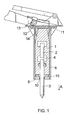
- FIG. 1 shows a simplified view of a percussion hammer according to the invention.
- a percussion device 1 comprises a percussion piston 2 arranged to move to and fro in the axial direction.
- the pressure of hydraulic fluid affects the percussion piston 2, but pneumatic and electric uses are also possible.
- the structure and operation of the percussion device 1 are as such known to those skilled in the art, wherefore a more detailed description thereof is not necessary in this context.
- a tool 3 is positioned as an extension of the percussion piston 2 in stroke direction A.
- the tool 3 has a strike-receiving surface, on which the front end of the percussion piston 2 strikes. It should be noted that in this application a reference to the front and bottom ends of the percussion hammer refers to the end, where the tool is located.
- a protective cover 8 is arranged around the percussion device 1 that protects the percussion device 1 from impurities and dents.
- the bottom end of the protective cover 8 comprises a transverse lower piece 9, through which the tool 3 penetrates.
- a seal 10 preventing impurities from entering inside the protective cover 8 is placed between the lower piece 9 and the tool 3.
- the protective cover 8 also comprises a transverse upper piece 11, which can be fastened to the upper end of the protective cover 8 by welding.
- the upper piece 11 may comprise holes from which said piece could be fastened using fastening bolts 12 or other appropriate fastening elements to a fastening part 13 in an excavator boom.
- a first damping element 14 can be placed between the percussion device 1 and the upper piece 11 and correspondingly a second damping element 15 can be placed between the percussion device 1 and the lower piece 9, whereby the percussion device 1 is supported by the elements 14 and 15 inside the protective cover 8.
- the percussion device 1 is able to move slightly in the axial direction during operation supported by the damping elements 14, 15.
- the damping elements 14 and 15 also damp vibration and noise.
- the sides of the protective cover 8 locate the percussion device 1 accurately in the transverse direction of the protective cover 8 to a pre-designed position. For this reason, the cross section profile of the protective cover 8 must be made fairly accurate.
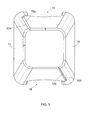
- Figures 2 and 3 illustrate the protective cover 8 without the upper piece 11 and the lower piece 9.
- the protective cover 8 is formed of two substantially L-shaped cover parts 16 and 17, whose longitudinal edges 16a and 17a and correspondingly 16b and 17b are arranged opposite to one another or at least nearly opposite each other.
- a tube that is substantially rectangular in cross section is formed.
- the cross section of the protective cover 8 may substantially resemble either a square or a rectangle.
- the cross section of the cover parts 16, 17 may substantially be constant along the length of the protective cover 8.
- the cross section of the cover parts 16, 17 may increase towards the back end of the protective cover 8, in which case the assembled protective cover 8 is wedge-shaped as shown in Figures 2, 3 and 14.
- the cover parts can be made of plate material and an L-shaped cross section profile is formed thereto using longitudinal bending. Furthermore, the longitudinal edges 16a, 16b, 17a, 17b can be provided with an appropriate welding bevel in order to alleviate the welded joints between the cover parts 16, 17.
- the upper end of the protective cover 8 according to Figures 2 and 3 comprises on the opposite sides thereof U-shaped cuts 18, upon which the percussion device 1 rests. For clarity, the possible openings and through holes of the protective cover are not shown in Figures 2 and 3.
- Figure 4 illustrates a cross section of the protective cover 8 according to the invention.
- the protective cover 8 is assembled of two cover parts 16, 17 having an L-shaped cross section.
- the first cover part 16 then comprises two sides 8a, 8b of the protective cover and correspondingly the second cover part 17 comprises sides 8c, 8d.
- the longitudinal joints between the cover parts 16, 17 are located in opposite corners 19a and 19b of the cross section of the protective cover 8. The joints thus endure heavy loads, since the corners 19a and 19b are relatively stiff. No bucklings occur in the corners.
- Figures 5, 6 and 7 show that the dimensions and form of the protective cover's 8 cross section can conveniently be adjusted during assembly.
- the assembly is carried out so that the cover parts 16 and 17 are arranged into an appropriate fastener, which positions the cover parts 16 and 17 in relation to one another in such a manner that the pre-designed dimensions and form of the cross section are achieved.
- the cover parts 16 and 17 are adjusted in relation to each other in the vertical direction Y so that distance a between the first horizontal side 8a and the second horizontal side 8c is at a minimum.
- Distance b between the vertical sides 8b and 8d can be kept unchanged, when dimension a is adjusted.
- the vertical dimension a is at a maximum.
- the adjustment margin inside and outside may vary about 1/3 of the plate thickness of the protective cover, which normally is fully adequate to compensate for possible inaccuracies in the cover portion structure.
- the horizontal dimension b of the protective cover is adjusted, whereby an root gap 21 of the size of the adjustment margin that a welded joint 20 tightly fills remains between the joint edges 16a and 17a of the cover parts 16 and 17 and also between 16b and 17b.
- the breadth of the root gap 21 may, if required, be about 1 to 2 mm, however, it generally remains smaller than 1/3 of the plate thickness of the protective cover.
- the welded joint 20 may be extended uniformly from the lower end of the protective cover 8 to the upper end thereof.
- one of the longitudinal opposite edges 16a or 17a and correspondingly 16b or 17b of the cover parts 16 and 17 in the protective cover 8 are bevelled and the other edge remains straight.
- the cover parts 16 and 17 can be moved in relation to one another as shown in Figure 11 merely in the vertical direction Y, and the vertical dimension a can be adjusted or only the horizontal dimension b can be adjusted as shown in Figure 13 using horizontal adjustment movement X. It is also possible to move the cover parts as shown in Figure 12 in direction Z, whereby dimensions a and b are adjusted simultaneously.
- Figure 14 shows another percussion hammer in cross cut.
- the solution of the invention allows manufacturing a wedge-shaped protective cover 8 tapering towards the lower end thereof.
- a wedge-shaped wear part 30 can be arranged into the wedge-shaped space formed between the inner surface of the protective cover 8 and the outer surface of the percussion device 1.
- the number of wear parts 30 is at least two and arranged on the opposite sides of the percussion device 1.
- the percussion device 1 is able to move slightly inside the protective cover 8 in the axial direction supported by the damping elements 14 and 15.
- the wear parts 30 thus support and guide the motion of the percussion device 1 body.
- the percussion device 1 slides, when the percussion hammer is used, in relation to the wear parts 30, wherefore the wear parts wear with time.
- the position of the wedge-shaped wear parts 30 can, however, conveniently, for instance when services are carried out, be adjusted in the vertical direction V in the wedge-shaped space between the protective cover and the percussion device, whereby the required support can be achieved also with worn wear parts 30.
- Such an adjustment allows employing the wear parts 30 considerably longer.
- the clearance between the wear parts 30 and the percussion device 1 body can be adjusted as desired.
- the wear parts 30 may comprise a fastening groove or the like on the surface at the protective cover 8 side, to which an adjustment screw 31 can be arranged so that the wear part can, if necessary, be moved in the vertical direction V.
- the adjustment of the wear parts 30 can be carried out outside the protective cover 8.
- a wear part 30' is indicated by a dashed line in Figure 14 that has worn in use and whose position is readjusted so that it is again able to provide the percussion device with the required support and guidance.
- the wear parts thus keep the percussion device in a predetermined position inside the protective cover and also prevent vibration and noise from being created.
- the wear parts can be made of for instance an appropriate plastic material that endures wear.
Landscapes
- Engineering & Computer Science (AREA)
- Mechanical Engineering (AREA)
- Mining & Mineral Resources (AREA)
- Civil Engineering (AREA)
- General Engineering & Computer Science (AREA)
- Structural Engineering (AREA)
- Percussive Tools And Related Accessories (AREA)
- Electrophonic Musical Instruments (AREA)
- Crushing And Grinding (AREA)
- Protection Of Pipes Against Damage, Friction, And Corrosion (AREA)
- Details Of Indoor Wiring (AREA)
- Earth Drilling (AREA)
Applications Claiming Priority (2)
| Application Number | Priority Date | Filing Date | Title |
|---|---|---|---|
| FI20011299A FI116475B (fi) | 2001-06-19 | 2001-06-19 | Menetelmä rikotuslaitteen suojakotelon valmistamiseksi ja rikotuslaite |
| FI20011299 | 2001-06-19 |
Publications (2)
| Publication Number | Publication Date |
|---|---|
| EP1270098A2 true EP1270098A2 (de) | 2003-01-02 |
| EP1270098A3 EP1270098A3 (de) | 2003-05-07 |
Family
ID=8561443
Family Applications (1)
| Application Number | Title | Priority Date | Filing Date |
|---|---|---|---|
| EP02100575A Withdrawn EP1270098A3 (de) | 2001-06-19 | 2002-05-29 | Verfahren zur Herstellung einer Schutzhülle für ein Zerkleinerungsgerät, und dieses Zerkleinerungsgerät |
Country Status (5)
| Country | Link |
|---|---|
| US (1) | US20020190092A1 (de) |
| EP (1) | EP1270098A3 (de) |
| JP (1) | JP2003001126A (de) |
| KR (1) | KR20020097007A (de) |
| FI (1) | FI116475B (de) |
Cited By (5)
| Publication number | Priority date | Publication date | Assignee | Title |
|---|---|---|---|---|
| EP1612336A1 (de) * | 2004-07-01 | 2006-01-04 | Sandvik Tamrock Oy | Brecherhammer |
| CN101392542B (zh) * | 2008-10-23 | 2010-12-08 | 山东卡特重工有限公司 | 一种可高温破碎作业的挖掘机 |
| CN102677725A (zh) * | 2012-06-12 | 2012-09-19 | 南通欧特建材设备有限公司 | 一种液压破碎器的直型壳体 |
| EP2635864A4 (de) * | 2010-11-03 | 2014-04-09 | Brokk Aktiebolag | Anordnung mit einem manövrierbaren arm zur zerstörung einer ferngesteuerten arbeitsmaschine und verwendung davon zur sanierung metallurgischer gefässe |
| WO2016193698A1 (en) * | 2015-06-01 | 2016-12-08 | Mountt&C Holdings Limited | Hydraulic breaker, in particular for an excavator |
Families Citing this family (6)
| Publication number | Priority date | Publication date | Assignee | Title |
|---|---|---|---|---|
| US9457401B2 (en) * | 2012-05-24 | 2016-10-04 | LGT Manufacturing Co., Inc. | Riser breaker assembly |
| CN105289793B (zh) * | 2015-11-17 | 2017-09-26 | 吉林大学 | 一种仿生破碎锤钎杆 |
| US10479373B2 (en) * | 2016-01-06 | 2019-11-19 | GM Global Technology Operations LLC | Determining driver intention at traffic intersections for automotive crash avoidance |
| CN107855698B (zh) * | 2017-12-13 | 2024-08-30 | 冯建强 | 一种破碎锤外壳焊接辅助装置及其焊接方法 |
| CN108080896B (zh) * | 2017-12-13 | 2020-01-17 | 安徽安通机械有限公司 | 一种破碎锤侧板的焊接装配方法 |
| CN107825146B (zh) * | 2017-12-13 | 2020-01-17 | 安徽安通机械有限公司 | 一种简易式液压锤外壳加工组装系统 |
Family Cites Families (20)
| Publication number | Priority date | Publication date | Assignee | Title |
|---|---|---|---|---|
| US1574563A (en) * | 1921-09-06 | 1926-02-23 | Albert W Heinle | Metallic structure and structural unit |
| FR752539A (fr) * | 1933-03-16 | 1933-09-25 | Ici Ltd | Procédé de fabrication d'éléments métalliques creux |
| US3067657A (en) * | 1957-06-21 | 1962-12-11 | Kenneth R Wiekhorst | Earth tamper |
| US3045834A (en) * | 1957-07-25 | 1962-07-24 | Edward A Seiz | Rack construction |
| US3557422A (en) * | 1968-09-27 | 1971-01-26 | Pfaff & Kendall | Method of forming a pole base structure |
| US3583499A (en) * | 1969-09-08 | 1971-06-08 | Hugo Cordes | Hydraulic pile extractor |
| US3866690A (en) * | 1972-09-25 | 1975-02-18 | Technology Inc Const | Hydraulically powered impact device |
| NL155066B (nl) * | 1974-09-09 | 1977-11-15 | Kooten Bv V | Cilinderstuk voor een heiblok. |
| FR2394004A1 (fr) * | 1977-06-07 | 1979-01-05 | Bignier Schmid Laurent | Procede et profiles pour la fabrication d'un tube de section droite polygonale |
| US4237987A (en) * | 1978-10-27 | 1980-12-09 | Sherman Victor L | Percussive tool |
| US4759412A (en) * | 1986-10-20 | 1988-07-26 | Brazell Ii James W | Rock breaking device |
| US5065824A (en) * | 1989-12-28 | 1991-11-19 | Esco Corporation | Hydraulically powered repetitive impact hammer |
| US5174388A (en) * | 1991-09-10 | 1992-12-29 | Williams Tunney E | Driver tool and method |
| US5497555A (en) * | 1994-12-19 | 1996-03-12 | Averbukh; Moshe | Electromagnetic percussion device |
| DE29503157U1 (de) * | 1995-02-27 | 1995-04-13 | Nagler, Jürgen, 58313 Herdecke | Zusatzgerät für einen Hydraulik- oder Pneumatikhammer insbesondere als Anbauteil an einen Hydraulikbagger |
| US5752571A (en) * | 1995-12-15 | 1998-05-19 | Sapozhnikov; Zinoviy A. | Apparatus for generating impacts |
| US6378951B1 (en) * | 1997-07-23 | 2002-04-30 | Hydroacoustics, Inc. | Vibratory pavement breaker |
| US6094881A (en) * | 1998-04-30 | 2000-08-01 | Con/Span Bridge Systems Inc. | Box shaped structural member with pultruded flanges and connecting webs |
| US6155353A (en) * | 1999-07-23 | 2000-12-05 | Ottestad; Jack B. | Impact tool |
| US6557647B2 (en) * | 2000-05-30 | 2003-05-06 | American Piledriving Equipment, Inc. | Impact hammer systems and methods |
-
2001
- 2001-06-19 FI FI20011299A patent/FI116475B/fi active IP Right Grant
-
2002
- 2002-05-29 EP EP02100575A patent/EP1270098A3/de not_active Withdrawn
- 2002-06-18 JP JP2002176733A patent/JP2003001126A/ja not_active Abandoned
- 2002-06-19 US US10/173,873 patent/US20020190092A1/en not_active Abandoned
- 2002-06-19 KR KR1020020034410A patent/KR20020097007A/ko not_active Withdrawn
Cited By (8)
| Publication number | Priority date | Publication date | Assignee | Title |
|---|---|---|---|---|
| EP1612336A1 (de) * | 2004-07-01 | 2006-01-04 | Sandvik Tamrock Oy | Brecherhammer |
| US7111691B2 (en) | 2004-07-01 | 2006-09-26 | Sandvik Tamrock Oy | Breaking hammer, and fastening element, side plate, and protective casing of breaking hammer |
| CN101392542B (zh) * | 2008-10-23 | 2010-12-08 | 山东卡特重工有限公司 | 一种可高温破碎作业的挖掘机 |
| EP2635864A4 (de) * | 2010-11-03 | 2014-04-09 | Brokk Aktiebolag | Anordnung mit einem manövrierbaren arm zur zerstörung einer ferngesteuerten arbeitsmaschine und verwendung davon zur sanierung metallurgischer gefässe |
| CN102677725A (zh) * | 2012-06-12 | 2012-09-19 | 南通欧特建材设备有限公司 | 一种液压破碎器的直型壳体 |
| WO2016193698A1 (en) * | 2015-06-01 | 2016-12-08 | Mountt&C Holdings Limited | Hydraulic breaker, in particular for an excavator |
| GB2555306A (en) * | 2015-06-01 | 2018-04-25 | Mountt&C Holdings Ltd | Hydraulic breaker, in particular for an excavator |
| GB2555306B (en) * | 2015-06-01 | 2019-12-04 | Mountt&C Holdings Ltd | Hydraulic breaker, in particular for an excavator |
Also Published As
| Publication number | Publication date |
|---|---|
| FI116475B (fi) | 2005-11-30 |
| FI20011299L (fi) | 2002-12-20 |
| EP1270098A3 (de) | 2003-05-07 |
| US20020190092A1 (en) | 2002-12-19 |
| FI20011299A0 (fi) | 2001-06-19 |
| JP2003001126A (ja) | 2003-01-07 |
| KR20020097007A (ko) | 2002-12-31 |
Similar Documents
| Publication | Publication Date | Title |
|---|---|---|
| EP1270098A2 (de) | Verfahren zur Herstellung einer Schutzhülle für ein Zerkleinerungsgerät, und dieses Zerkleinerungsgerät | |
| EP0922539B1 (de) | Anordung im Bezüg mit einem Hydraulischen Brechgerät | |
| US9630308B2 (en) | Demolition hammer with reversible housing and interchangeable wear plate arrangement | |
| US9279232B2 (en) | Front head nut pocket configuration for hydraulic hammer | |
| EP2652210B1 (de) | Gesteinsklammergreifer für einen schlaghammer | |
| JP4763362B2 (ja) | 破砕ハンマと、破砕ハンマの固定要素、側板および保護ケーシング | |
| EP0947293B2 (de) | Hydraulische Schlagvorrichtung | |
| KR102399492B1 (ko) | 금형가공용 고정지그 | |
| US10226858B2 (en) | Demolition hammer with wear plate system having debris channels | |
| US20170036336A1 (en) | Hammer assembly | |
| CN105239923A (zh) | 破碎装置 | |
| USRE49552E1 (en) | Rock claw for demolition hammer | |
| US10029358B2 (en) | Hydraulic hammer with clearance control system | |
| US11752612B2 (en) | Dust suppression system for hammers | |
| KR101621955B1 (ko) | 천공장비용 가이드 시스템 | |
| KR102449887B1 (ko) | 금형가공용 고정지그 | |
| JP6599268B2 (ja) | トンネルの内面に溝を形成する方法 | |
| US10065301B2 (en) | Lower buffer and bushing protector | |
| AU2026202858A1 (en) | Dust suppression system for hammers | |
| AU2022235263A1 (en) | Linkage for arm assembly with reduced weld fatigue | |
| KR20260019206A (ko) | 건설중장비용 유압 호스의 진동 및 충격 저감 장치 | |
| WO2005080694A1 (en) | Arrangement for steering crosswise movement of working apparatus | |
| KR20090002928U (ko) | 파쇄 해머 및 그의 보호 케이싱 |
Legal Events
| Date | Code | Title | Description |
|---|---|---|---|
| PUAI | Public reference made under article 153(3) epc to a published international application that has entered the european phase |
Free format text: ORIGINAL CODE: 0009012 |
|
| AK | Designated contracting states |
Kind code of ref document: A2 Designated state(s): AT BE CH CY DE DK ES FI FR GB GR IE IT LI LU MC NL PT SE TR |
|
| AX | Request for extension of the european patent |
Free format text: AL;LT;LV;MK;RO;SI |
|
| PUAL | Search report despatched |
Free format text: ORIGINAL CODE: 0009013 |
|
| AK | Designated contracting states |
Designated state(s): AT BE CH CY DE DK ES FI FR GB GR IE IT LI LU MC NL PT SE TR |
|
| AX | Request for extension of the european patent |
Extension state: AL LT LV MK RO SI |
|
| RIC1 | Information provided on ipc code assigned before grant |
Ipc: 7B 21C 37/15 B Ipc: 7E 02F 3/96 B Ipc: 7B 21C 37/08 A |
|
| 17P | Request for examination filed |
Effective date: 20030814 |
|
| AKX | Designation fees paid |
Designated state(s): DE ES FR GB IT SE |
|
| 17Q | First examination report despatched |
Effective date: 20060704 |
|
| STAA | Information on the status of an ep patent application or granted ep patent |
Free format text: STATUS: THE APPLICATION IS DEEMED TO BE WITHDRAWN |
|
| 18D | Application deemed to be withdrawn |
Effective date: 20061115 |