EP1270102A2 - Spule zum Wickeln von Bamdmaterial - Google Patents
Spule zum Wickeln von Bamdmaterial Download PDFInfo
- Publication number
- EP1270102A2 EP1270102A2 EP02445084A EP02445084A EP1270102A2 EP 1270102 A2 EP1270102 A2 EP 1270102A2 EP 02445084 A EP02445084 A EP 02445084A EP 02445084 A EP02445084 A EP 02445084A EP 1270102 A2 EP1270102 A2 EP 1270102A2
- Authority
- EP
- European Patent Office
- Prior art keywords
- bobbin
- slot
- circumference
- band material
- band
- Prior art date
- Legal status (The legal status is an assumption and is not a legal conclusion. Google has not performed a legal analysis and makes no representation as to the accuracy of the status listed.)
- Withdrawn
Links
Images
Classifications
-
- B—PERFORMING OPERATIONS; TRANSPORTING
- B21—MECHANICAL METAL-WORKING WITHOUT ESSENTIALLY REMOVING MATERIAL; PUNCHING METAL
- B21C—MANUFACTURE OF METAL SHEETS, WIRE, RODS, TUBES, PROFILES OR LIKE SEMI-MANUFACTURED PRODUCTS OTHERWISE THAN BY ROLLING; AUXILIARY OPERATIONS USED IN CONNECTION WITH METAL-WORKING WITHOUT ESSENTIALLY REMOVING MATERIAL
- B21C47/00—Winding-up, coiling or winding-off metal wire, metal band or other flexible metal material characterised by features relevant to metal processing only
- B21C47/32—Tongs or gripping means specially adapted for reeling operations
- B21C47/323—Slits or pinces on the cylindrical wall of a reel or bobbin, adapted to grip the end of the material being wound
-
- B—PERFORMING OPERATIONS; TRANSPORTING
- B21—MECHANICAL METAL-WORKING WITHOUT ESSENTIALLY REMOVING MATERIAL; PUNCHING METAL
- B21C—MANUFACTURE OF METAL SHEETS, WIRE, RODS, TUBES, PROFILES OR LIKE SEMI-MANUFACTURED PRODUCTS OTHERWISE THAN BY ROLLING; AUXILIARY OPERATIONS USED IN CONNECTION WITH METAL-WORKING WITHOUT ESSENTIALLY REMOVING MATERIAL
- B21C47/00—Winding-up, coiling or winding-off metal wire, metal band or other flexible metal material characterised by features relevant to metal processing only
- B21C47/28—Drums or other coil-holders
-
- B—PERFORMING OPERATIONS; TRANSPORTING
- B65—CONVEYING; PACKING; STORING; HANDLING THIN OR FILAMENTARY MATERIAL
- B65H—HANDLING THIN OR FILAMENTARY MATERIAL, e.g. SHEETS, WEBS, CABLES
- B65H75/00—Storing webs, tapes, or filamentary material, e.g. on reels
- B65H75/02—Cores, formers, supports, or holders for coiled, wound, or folded material, e.g. reels, spindles, bobbins, cop tubes, cans, mandrels or chucks
- B65H75/18—Constructional details
- B65H75/28—Arrangements for positively securing ends of material
Definitions
- the present invention relates to a bobbin for the winding of band material as is stated in the introduction of claim 1.
- Bobbins, or reels, rolls, drums and the like are used for the winding or reeling of different types of material.
- One such use is for the winding of band material.
- the present invention is in particular adapted for the winding of band material, particularly band steel.
- the bobbin In this connection, usually bobbins having a winding surface along the circumference thereof are used.
- the bobbin according to prior art is provided with a fixed entering slot.
- said slot is a transversal slot in the radial direction, i.e. the slot extends from the surface following the circumference and inwards in the bobbin, in the radial direction.
- This previously known design of entering slot implies a plurality of disadvantages.
- One disadvantage is that the slot does not lock the end of the band material with certainty in the proper slot, but the end may occasionally slide out of the slot when the winding is begun. This may lead to the winding having to be begun again from the beginning.
- Another disadvantage is that an irregularity is formed where the band material leaves the slot, which results in a fold being formed on the thin band steel. This fold goes through a plurality of turns in the beginning of the winding, which results in these material turns not being able to be utilized by the end user, but have to be discarded.
- This also means that parts of the band are wound without contact with the band turns positioned below and above, respectively, and this may initiate a lateral sliding between the band turns.
- the innermost band turns are not fixed in relation to each other.
- the object of the present invention is to solve the above mentioned problem. This object is obtained by a bobbin, which has been given the new features that are stated in the characterizing part of claim 1.
- a bobbin is characterized in that it is provided with at least one resilient portion along the circumference thereof and that at least one slot for fixing an end of the band material is arranged in said resilient portion of the bobbin.
- the band end will, at springing down, be pinched in place when the edges of the slot opening are brought towards each other at springing down, and thereby the band end is prevented from sliding out of the position thereof as long as the spring is loaded by wound band material.
- An additional advantage of the present invention is that the achieved springing away of the portion where the fixing slot is, provides a smooth ridgeless transition for the band material, both between the inserted band end and the beginning of the first winding turn, and also between a number of band turns following thereafter where they are overlapping each other, and thereby unfavourable band folds are avoided.
- This springing away an improved material support is also obtained radially as well as axially, which prevents lateral slidings between the band turns. This in turn makes it possible to completely utilize all wound material, since no band folds are found, which gives economical advantages for the user.
- the resilient portion is formed as two resilient tongues, between which the slot is arranged.
- Said tongues may be arranged by the bobbin having been provided with at least one recess extending in the direction of circumference and at a certain distance from the surface following the circumference.
- the bobbin also comprises a stroke-limiting device arranged in an area where the tongues connect to each other and where said slot is arranged.
- This stroke-limiting device prevents the resilient portion from being pressed in further than what is suitable in view of the fact that the wound band material all the time is to have a support both axially and radially in the form of friction between the band turns.
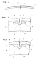
- Figure 1 shows, schematically in a side view, a part of a bobbin according to prior art with two parts of a band.
- Figure 2 shows, schematically in perspective, a part of a bobbin according to the present invention having a resilient portion with a fixing slot for a band end.
- Figure 3 shows, schematically in a side view, the part of the bobbin in figure 2 with two parts of a band.
- the bobbin according to prior art illustrated in figure 1 comprises a surface 1 along the circumference thereof, on which band material 3, 4 have been wound in the direction of the circumference. For the sake of clarity, only a part of a first 3 and a second 4, respectively, layer/turn of band material 3, 4 is shown on the bobbin. An undesired deformation 11 arises in the band material.
- the bobbin according to the invention illustrated in figures 2 and 3 comprises a surface 1 along the circumference thereof, on which band material 3, 4 is wound in the direction of the circumference.
- the bobbin is in a starting position without band material and in figure 3 the band material has been wound, only a part of a first 3 and a second 4, respectively, layer/turn of band material 3, 4 being shown.
- a slot 2 is arranged in the surface 1. The slot 2 extends inwards, in the radial direction, in the bobbin and normally runs all over the transversal width thereof. Said slot 2 is intended for the fixing of an end of the band material 3, 4 that should be wound.
- the opening of the slot 2 has a width (in the direction of circumference) which is only somewhat greater than the thickness of the material 3, 4 that should be wound.
- the width of the opening should be adapted so that it is large enough for the band end to be easily inserted into the slot 2 at the same time as the opening should be narrow enough for clamping the band end at a small springing down of the slot portion, see figure 3. No undesired deformation arises in the band material.
- the slot 2 is arranged in a part of the bobbin, which is formed as a resilient portion.
- This resilient portion comprises two resilient tongues 5, 6, between which the slot 2 is arranged.
- a recess 8 is arranged which extends in the direction of circumference and at a certain distance from the surface 1 following the circumference. It is this recess 8 that enables springing down of the tongues 5, 6.
- the material in the bobbin has to be such that springing down becomes feasible.
- the slot 2 as such contributes to enable the springing down.
- the slot 2 does not preferably extend all the way down to the recess 8, i.e. it is not a through slot which divides the tongues 5, 6, even if it would of course be fully feasible.
- a shoulder 9 is arranged, which works as a stroke-limiting device 9.
- This shoulder is formed as a portion of the resilient tongues 5, 6 protruding into the recess 8, i.e. it projects in the radial direction inwards on the bobbin.
- the slot 2 extends partly into said shoulder 9, and could also go through the shoulder 9.
- the recess 8 is advantageously so formed that it is provided with a depression 10 under said shoulder 9.
- the possibility of springing down is determined by the free distance that exists between the lower part of the shoulder 9 and the bottom of the recess 8 or of the depression 10.
- the depression 10 in combination with the shoulder 9 makes the springing down of the tongues 5, 6 and in particular the area where the slot 2 is situated being limited by the fact that the shoulder 9 knocks against the bottom of the depression 10.
Landscapes
- Engineering & Computer Science (AREA)
- Mechanical Engineering (AREA)
- Storage Of Web-Like Or Filamentary Materials (AREA)
Applications Claiming Priority (2)
| Application Number | Priority Date | Filing Date | Title |
|---|---|---|---|
| SE0102241A SE523551C2 (sv) | 2001-06-25 | 2001-06-25 | Bobin för upplindning av bandmaterial |
| SE0102241 | 2001-06-25 |
Publications (2)
| Publication Number | Publication Date |
|---|---|
| EP1270102A2 true EP1270102A2 (de) | 2003-01-02 |
| EP1270102A3 EP1270102A3 (de) | 2004-04-07 |
Family
ID=20284593
Family Applications (1)
| Application Number | Title | Priority Date | Filing Date |
|---|---|---|---|
| EP02445084A Withdrawn EP1270102A3 (de) | 2001-06-25 | 2002-06-24 | Spule zum Wickeln von Bamdmaterial |
Country Status (2)
| Country | Link |
|---|---|
| EP (1) | EP1270102A3 (de) |
| SE (1) | SE523551C2 (de) |
Cited By (1)
| Publication number | Priority date | Publication date | Assignee | Title |
|---|---|---|---|---|
| CN114654776A (zh) * | 2022-03-25 | 2022-06-24 | 王伟 | 一种建筑保温材料的制备方法 |
Family Cites Families (5)
| Publication number | Priority date | Publication date | Assignee | Title |
|---|---|---|---|---|
| US3593938A (en) * | 1969-10-08 | 1971-07-20 | United States Steel Corp | Method and apparatus for processing strip |
| DE3503786A1 (de) * | 1985-02-05 | 1986-08-07 | Pahl'sche Gummi- und Asbest-Gesellschaft "Paguag" GmbH & Co, 4000 Düsseldorf | Haspelanlage |
| DE4410308A1 (de) * | 1993-12-21 | 1995-06-22 | Sundwiger Eisen Maschinen | Wickeltrommel einer Haspel für Bänder mit Klemmvorrichtung für den Bandanfang |
| US5785272A (en) * | 1996-11-05 | 1998-07-28 | Kvaerner U.S. Inc. | Coiler spool with built-in gripper slot |
| JP3271746B2 (ja) * | 1997-06-30 | 2002-04-08 | 川崎製鉄株式会社 | リバースミルの鋼帯の巻取方法及び巻取ドラム |
-
2001
- 2001-06-25 SE SE0102241A patent/SE523551C2/sv not_active IP Right Cessation
-
2002
- 2002-06-24 EP EP02445084A patent/EP1270102A3/de not_active Withdrawn
Cited By (1)
| Publication number | Priority date | Publication date | Assignee | Title |
|---|---|---|---|---|
| CN114654776A (zh) * | 2022-03-25 | 2022-06-24 | 王伟 | 一种建筑保温材料的制备方法 |
Also Published As
| Publication number | Publication date |
|---|---|
| EP1270102A3 (de) | 2004-04-07 |
| SE0102241D0 (sv) | 2001-06-25 |
| SE523551C2 (sv) | 2004-04-27 |
| SE0102241L (sv) | 2002-12-26 |
Similar Documents
| Publication | Publication Date | Title |
|---|---|---|
| US5586733A (en) | Take-up reel for metallic filaments | |
| US2695139A (en) | Core member for coils | |
| EP1181221A1 (de) | Verbesserte bodenanordnung für eine spiraldrahtverpackung | |
| HU219937B (hu) | Egyszer használatos, fémmentes dob, folytonos flexibilis termékekhez, például kötelekhez, valamint eljárás ilyen dob gyártására | |
| CZ310894A3 (en) | Self-locking clamp | |
| US4828192A (en) | Thread feeder | |
| US7121501B1 (en) | Wire spooling system | |
| US5064136A (en) | Payout tube for container packaged coiled filament | |
| US4978084A (en) | Spool for photographic film or other web material | |
| EP3109081B1 (de) | Rolloanordnung | |
| JPH0666213B2 (ja) | コイル巻枠 | |
| JP3575086B2 (ja) | 電動機の巻線保護カバーの装着方法 | |
| US3622099A (en) | Plastic ribbon spool | |
| US380873A (en) | Conductor-strainer | |
| ITFI20000011A1 (it) | Supporto a tubetto in resina sintetica per l'avvolgimento di filati in rocche, con un mezzo di ritegno automatico per le spire di filo di ri | |
| US20100025520A1 (en) | Winding support and use of a winding carrier | |
| JPH08245083A (ja) | コード類巻取り用リール | |
| US1798259A (en) | Shade roller and fastener | |
| JP2576330Y2 (ja) | スチールコード類用巻取りリール | |
| JP5203863B2 (ja) | 長尺体用スプール | |
| WO2025147738A1 (en) | Tape applicator with constant tape tension | |
| JP2002153189A (ja) | 釣糸用スプール | |
| US1772204A (en) | Metal bobbin | |
| US2175623A (en) | Metal coil and fastener therefor | |
| JPH061569Y2 (ja) | 金属線条体用リール |
Legal Events
| Date | Code | Title | Description |
|---|---|---|---|
| PUAI | Public reference made under article 153(3) epc to a published international application that has entered the european phase |
Free format text: ORIGINAL CODE: 0009012 |
|
| AK | Designated contracting states |
Kind code of ref document: A2 Designated state(s): AT BE CH CY DE DK ES FI FR GB GR IE IT LI LU MC NL PT SE TR |
|
| AX | Request for extension of the european patent |
Free format text: AL;LT;LV;MK;RO;SI |
|
| PUAL | Search report despatched |
Free format text: ORIGINAL CODE: 0009013 |
|
| AK | Designated contracting states |
Kind code of ref document: A3 Designated state(s): AT BE CH CY DE DK ES FI FR GB GR IE IT LI LU MC NL PT SE TR |
|
| AX | Request for extension of the european patent |
Extension state: AL LT LV MK RO SI |
|
| RIC1 | Information provided on ipc code assigned before grant |
Ipc: 7B 65H 75/28 B Ipc: 7B 21C 47/28 B Ipc: 7B 21C 47/32 A |
|
| 17P | Request for examination filed |
Effective date: 20041007 |
|
| AKX | Designation fees paid |
Designated state(s): DE FI FR GB |
|
| 17Q | First examination report despatched |
Effective date: 20050311 |
|
| STAA | Information on the status of an ep patent application or granted ep patent |
Free format text: STATUS: THE APPLICATION IS DEEMED TO BE WITHDRAWN |
|
| 18D | Application deemed to be withdrawn |
Effective date: 20050722 |