EP1270140A2 - Anlage zum Zusammenfügen und Längsschweissen von aus Blechen o.dgl. gebogenen Rohren - Google Patents
Anlage zum Zusammenfügen und Längsschweissen von aus Blechen o.dgl. gebogenen Rohren Download PDFInfo
- Publication number
- EP1270140A2 EP1270140A2 EP02013669A EP02013669A EP1270140A2 EP 1270140 A2 EP1270140 A2 EP 1270140A2 EP 02013669 A EP02013669 A EP 02013669A EP 02013669 A EP02013669 A EP 02013669A EP 1270140 A2 EP1270140 A2 EP 1270140A2
- Authority
- EP
- European Patent Office
- Prior art keywords
- wheels
- longitudinal direction
- longitudinal
- welding
- measuring device
- Prior art date
- Legal status (The legal status is an assumption and is not a legal conclusion. Google has not performed a legal analysis and makes no representation as to the accuracy of the status listed.)
- Granted
Links
Images


Classifications
-
- B—PERFORMING OPERATIONS; TRANSPORTING
- B23—MACHINE TOOLS; METAL-WORKING NOT OTHERWISE PROVIDED FOR
- B23K—SOLDERING OR UNSOLDERING; WELDING; CLADDING OR PLATING BY SOLDERING OR WELDING; CUTTING BY APPLYING HEAT LOCALLY, e.g. FLAME CUTTING; WORKING BY LASER BEAM
- B23K37/00—Auxiliary devices or processes, not specially adapted for a procedure covered by only one of the other main groups of this subclass
- B23K37/04—Auxiliary devices or processes, not specially adapted for a procedure covered by only one of the other main groups of this subclass for holding or positioning work
- B23K37/053—Auxiliary devices or processes, not specially adapted for a procedure covered by only one of the other main groups of this subclass for holding or positioning work aligning cylindrical work; Clamping devices therefor
- B23K37/0533—External pipe alignment clamps
-
- B—PERFORMING OPERATIONS; TRANSPORTING
- B23—MACHINE TOOLS; METAL-WORKING NOT OTHERWISE PROVIDED FOR
- B23K—SOLDERING OR UNSOLDERING; WELDING; CLADDING OR PLATING BY SOLDERING OR WELDING; CUTTING BY APPLYING HEAT LOCALLY, e.g. FLAME CUTTING; WORKING BY LASER BEAM
- B23K2101/00—Articles made by soldering, welding or cutting
- B23K2101/04—Tubular or hollow articles
Definitions
- the invention relates to a plant for assembly and longitudinal welding of sheet metal or the like.
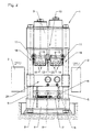
- bent pipes consisting of a system bed, on the sides or corners Stands are arranged, being on the upper table surface of the Plant bed a roller conveyor is provided on which the pipes be moved lengthways, one at the top of the stand attached truss, one attached to the truss and vertically movable working head with one in the longitudinal direction welding device arranged between unrolling devices, and laterally arranged, vertically movable and in Crosswise adjustable guide devices with rollers.
- the invention is therefore based on the object of a system to create the specified type with which an edge offset of pipes to be welded lengthways very easily and can be individually adjusted and the gap of the slot is maintained in accordance with the requirements for welding.
- the system according to the invention is characterized above all by this from that the two juxtaposed wheels of the Unwinding device on the working head on one side of the edge of the slot.
- the wheels are pivoted together with their central axes, i.e. the upstanding edge of the tube is through a wheel in its Position pressed, the lower edge of the tube from the other wheel is relieved. A gap change occurs not on.
- the wheels can individually respective edge offset can be adjusted so that when welding the slot always meets the requirements.
- bent tubes 2 preferably on its longitudinal edges 3 (see FIG. 3)
- Preparation of the weld seam consists of a system bed 4, on the sides or corners of which stand 5 is arranged or are clamped.
- a roller conveyor 7 is provided, on which the tubes 2 different sizes lie on and moved in the longitudinal direction become.
- the rollers 8 of the roller conveyor 7 are diaboloidal educated.
- a crossmember 9 is attached to the upper end of the stand 5, which in turn has a vertically movable working head 10 is provided, one in the longitudinal direction between two Rolling devices 11 arranged welding device 12 having.
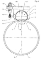
- the unrolling devices 11 each consist at least from two wheels arranged next to each other at a distance a 13 having wheels 14, which with their concentric Central axes 15 together around one on the longitudinal central axis 16 the system 1 lying pivot point 17 by means of a Swivel device 18 are rotatable (see in particular in this regard 3 and 4).
- each preferably has Unrolling device 11 two in the longitudinal direction one behind the other arranged pairs of wheels 14.
- the swivel device 18 consists of a side next to the longitudinal central axis 16 of the system 1 pivotally mounted Hydraulic cylinder 19, with its piston rod 20 on one Attacks lever 21 which is connected to a housing 22 in which the pairs of wheels 14 are mounted.
- Measuring device 23 In the longitudinal direction in front of the welding device 12 is one Measuring device 23 is provided, which is preferably a laser measuring device is.
- the system 1 has vertically movable and in Guide devices 24 with rollers 25 that can be moved in the transverse direction on the individually different sizes of pipes 2 can be adjusted (see Fig. 1).
- a pipe 2 is fed to the plant 1, the pipe being on the roller conveyor 7 is transported.
- the side Guide devices 24 and the working head 10 with the Unrolling devices 11 are brought up to the tube 2.
- the measuring device 23 then begins the edge offset b and measure the gap of the slot 26 of the tube 2, from which the necessary angle of rotation ⁇ results, which the Swivel device 18 must compensate.
- the Hydraulic cylinder 19 pressurized and the piston rod 20 pulls or pushes the lever 21, the housing 22 and the Turn wheels 13 around pivot point 17. Thereby the high standing Edge 3 of the tube 2 by a wheel 13 in its position pressed, the lower edge 3 of the tube 2 from the other wheel 13 is relieved.
- the CNC control the system 1 ensures that the pairs of rollers 14 constantly at the Compensate for edge offset b.
Landscapes
- Physics & Mathematics (AREA)
- Optics & Photonics (AREA)
- Engineering & Computer Science (AREA)
- Mechanical Engineering (AREA)
- Butt Welding And Welding Of Specific Article (AREA)
- Bending Of Plates, Rods, And Pipes (AREA)
- Laser Beam Processing (AREA)
Abstract
Description
- Fig. 1
- eine Vorderansicht der Anlage,
- Fig. 2
- die Seitenansicht der Anlage,
- Fig. 3
- eine Vorderansicht der Abrolleinrichtung, die an einem Rohr angreift, das einen Kantenversatz aufweist, und
- Fig. 4
- die Vorderansicht der Abrolleinrichtung nach dem Schwenken der Ränder zum Kantenausgleich.
Claims (5)
- Anlage zum Zusammenfügen und Längsschweißen von aus Blechen o.dgl. gebogenen Rohren, bestehend aus einem Anlagenbett, an dessen Seiten bzw. Ecken Ständer angeordnet sind, wobei auf der oberen Tischfläche des Anlagenbettes ein Rollengang vorgesehen ist, auf dem die Rohre in Längsrichtung bewegt werden, einer am oberen Ende der Ständer angebrachten Traverse, einem an der Traverse angebrachten und vertikal verfahrbaren Arbeitskopf mit einer in Längsrichtung zwischen Abrolleinrichtungen angeordneten Schweißeinrichtung, und seitlich angeordneten, vertikal verfahrbaren und in Querrichtung zustellbaren Führungseinrichtungen mit Rollen, dadurch gekennzeichnet, daß die Abrolleinrichtungen (11) am Arbeitskopf (10) jeweils mindestens aus einem zwei nebeneinander mit Abstand (a) angeordnete Räder (13) aufweisenden Räderpaar (14) bestehen, wobei die Räder (13) mit ihren konzentrischen Mittelachsen (15) gemeinsam um einen auf der Längsmittelachse (16) der Anlage (1) liegenden Drehpunkt (17) mittels einer Schwenkeinrichtung (18) drehbar sind.
- Anlage nach Anspruch 1, dadurch gekennzeichnet, daß jede Abrolleinrichtung (11) zwei in Längsrichtung hintereinander angeordnete Räderpaare (14) aufweist.
- Anlage nach Anspruch 1 oder 2, dadurch gekennzeichnet, daß die Schwenkeinrichtung (18) aus einem seitlich neben der Längsmittelachse (16) der Anlage (1) schwenkbar gelagerten Hydraulik-Zylinder (19) besteht, der mit seiner Kolbenstange (20) an einem Hebel (21) angreift, der mit einem Gehäuse (22) verbunden ist, in dem die Räderpaare (14) gelagert sind.
- Anlage nach einem der Ansprüche 1 bis 3, dadurch gekennzeichnet, daß in Längsrichtung vor der Schweißeinrichtung (12) eine Meßeinrichtung (23) vorgesehen ist.
- Anlage nach Anspruch 4, dadurch gekennzeichnet, daß die Meßeinrichtung (23) eine Laser-Meßeinrichtung ist.
Applications Claiming Priority (2)
| Application Number | Priority Date | Filing Date | Title |
|---|---|---|---|
| DE10131461A DE10131461C1 (de) | 2001-06-29 | 2001-06-29 | Anlage zum Zusammenfügen und Längsschweißen von aus Blechen oder dergleichen gebogenen Rohren |
| DE10131461 | 2001-06-29 |
Publications (3)
| Publication Number | Publication Date |
|---|---|
| EP1270140A2 true EP1270140A2 (de) | 2003-01-02 |
| EP1270140A3 EP1270140A3 (de) | 2004-12-29 |
| EP1270140B1 EP1270140B1 (de) | 2007-08-08 |
Family
ID=7689952
Family Applications (1)
| Application Number | Title | Priority Date | Filing Date |
|---|---|---|---|
| EP02013669A Expired - Lifetime EP1270140B1 (de) | 2001-06-29 | 2002-06-20 | Anlage zum Zusammenfügen und Längsschweissen von aus Blechen o.dgl. gebogenen Rohren |
Country Status (3)
| Country | Link |
|---|---|
| EP (1) | EP1270140B1 (de) |
| AT (1) | ATE369230T1 (de) |
| DE (1) | DE10131461C1 (de) |
Cited By (13)
| Publication number | Priority date | Publication date | Assignee | Title |
|---|---|---|---|---|
| CN102328163A (zh) * | 2011-06-10 | 2012-01-25 | 苏州九方焊割科技有限公司 | 一种预焊机的合拢装置 |
| CN101758352B (zh) * | 2009-11-17 | 2012-02-08 | 武汉法利普纳泽切割系统有限公司 | 薄壁圆管纵缝激光焊接定位装置 |
| CN102909461A (zh) * | 2012-11-12 | 2013-02-06 | 中国石化集团江汉石油管理局沙市钢管厂 | 精焊门架自适应驱动装置 |
| CN105414832A (zh) * | 2016-01-11 | 2016-03-23 | 江苏德创制管有限公司 | 一种用于管件焊接的装置 |
| CN105666026A (zh) * | 2016-04-07 | 2016-06-15 | 镇江远大传动机械有限公司 | 一种用于花键轴管与焊接叉的焊接支撑机构 |
| CN106425193A (zh) * | 2015-08-12 | 2017-02-22 | 王亚萍 | 一种纵缝自动焊接机 |
| CN106493501A (zh) * | 2016-10-31 | 2017-03-15 | 亿和精密工业(苏州)有限公司 | 管件焊接治具及焊接方法 |
| CN110977155A (zh) * | 2019-12-26 | 2020-04-10 | 罗细池 | 一种圆管件激光加工装置 |
| CN111468966A (zh) * | 2020-05-11 | 2020-07-31 | 成都航利航空科技有限责任公司 | 一种弯管类零件通用夹具及其使用方法 |
| CN111515610A (zh) * | 2020-04-30 | 2020-08-11 | 华育昌(肇庆)智能科技研究有限公司 | 自动焊接机器人 |
| CN117798566A (zh) * | 2024-02-29 | 2024-04-02 | 交城县天晴机械铸造有限公司 | 一种纵向焊缝双面焊接设备 |
| CN118720622A (zh) * | 2024-06-27 | 2024-10-01 | 南通德邦新材料科技有限公司 | 一种精准定位焊接设备 |
| CN120347416A (zh) * | 2025-06-13 | 2025-07-22 | 中国化学工程第十一建设有限公司 | 一种立式储罐的自动焊接装置 |
Families Citing this family (4)
| Publication number | Priority date | Publication date | Assignee | Title |
|---|---|---|---|---|
| DE102005022244B4 (de) * | 2005-05-13 | 2007-07-19 | Eroform Edelstahl Gmbh | Führungs- und Verformungssystem, dessen Verwendung sowie Verfahren zur Herstellung von geschweißten Rohren |
| CN106312294B (zh) * | 2016-11-07 | 2018-08-28 | 中色(天津)特种材料有限公司 | 针对水冷电机壳直缝焊接的工装夹具及直缝焊接工艺 |
| CN110315274A (zh) * | 2019-07-16 | 2019-10-11 | 无锡金红鹰工业自动化有限公司 | 一种长圆筒直缝焊接工作站 |
| CN110773849B (zh) * | 2019-10-12 | 2022-03-25 | 河北省机电一体化中试基地有限公司 | 一种龙门式塔管合缝焊接机 |
Family Cites Families (5)
| Publication number | Priority date | Publication date | Assignee | Title |
|---|---|---|---|---|
| US1952319A (en) * | 1932-07-29 | 1934-03-27 | George K Hull | Pipe assembling and welding apparatus |
| DE2002015C3 (de) * | 1970-01-17 | 1979-03-15 | Deuzer Maschinenfabrik Heitze Kg, 5902 Netphen | Vorrichtung zum Längsschweißen von rohrförmigen Werkstücken |
| JPS5316389B2 (de) * | 1972-03-31 | 1978-05-31 | ||
| DE3113769C1 (de) * | 1981-04-04 | 1982-10-28 | August Wilhelm 5901 Wilnsdorf Schäfer | Vorrichtung zum Ausrichten sowie Halten eines Rohrschusses und zum nachfolgenden Längsverschweißen stoßender freier Randbereiche |
| DE9110716U1 (de) * | 1991-08-29 | 1991-11-21 | Riedl, Hubert, 89358 Kammeltal | Längsnaht-Schweißmaschine mit einem klappbaren Gegenhalter |
-
2001
- 2001-06-29 DE DE10131461A patent/DE10131461C1/de not_active Expired - Fee Related
-
2002
- 2002-06-20 AT AT02013669T patent/ATE369230T1/de active
- 2002-06-20 EP EP02013669A patent/EP1270140B1/de not_active Expired - Lifetime
Cited By (18)
| Publication number | Priority date | Publication date | Assignee | Title |
|---|---|---|---|---|
| CN101758352B (zh) * | 2009-11-17 | 2012-02-08 | 武汉法利普纳泽切割系统有限公司 | 薄壁圆管纵缝激光焊接定位装置 |
| CN102328163A (zh) * | 2011-06-10 | 2012-01-25 | 苏州九方焊割科技有限公司 | 一种预焊机的合拢装置 |
| CN102909461A (zh) * | 2012-11-12 | 2013-02-06 | 中国石化集团江汉石油管理局沙市钢管厂 | 精焊门架自适应驱动装置 |
| CN102909461B (zh) * | 2012-11-12 | 2014-12-17 | 中石化石油工程机械有限公司沙市钢管厂 | 精焊门架自适应驱动装置 |
| CN106425193A (zh) * | 2015-08-12 | 2017-02-22 | 王亚萍 | 一种纵缝自动焊接机 |
| CN105414832B (zh) * | 2016-01-11 | 2017-09-19 | 江苏德创制管有限公司 | 一种用于管件焊接的装置 |
| CN105414832A (zh) * | 2016-01-11 | 2016-03-23 | 江苏德创制管有限公司 | 一种用于管件焊接的装置 |
| CN105666026A (zh) * | 2016-04-07 | 2016-06-15 | 镇江远大传动机械有限公司 | 一种用于花键轴管与焊接叉的焊接支撑机构 |
| CN106493501A (zh) * | 2016-10-31 | 2017-03-15 | 亿和精密工业(苏州)有限公司 | 管件焊接治具及焊接方法 |
| CN106493501B (zh) * | 2016-10-31 | 2018-11-23 | 亿和精密工业(苏州)有限公司 | 管件焊接治具及焊接方法 |
| CN110977155A (zh) * | 2019-12-26 | 2020-04-10 | 罗细池 | 一种圆管件激光加工装置 |
| CN110977155B (zh) * | 2019-12-26 | 2021-06-08 | 湖南旗胜精密制造有限公司 | 一种圆管件激光加工装置 |
| CN111515610A (zh) * | 2020-04-30 | 2020-08-11 | 华育昌(肇庆)智能科技研究有限公司 | 自动焊接机器人 |
| CN111468966A (zh) * | 2020-05-11 | 2020-07-31 | 成都航利航空科技有限责任公司 | 一种弯管类零件通用夹具及其使用方法 |
| CN117798566A (zh) * | 2024-02-29 | 2024-04-02 | 交城县天晴机械铸造有限公司 | 一种纵向焊缝双面焊接设备 |
| CN117798566B (zh) * | 2024-02-29 | 2024-05-17 | 交城县天晴机械铸造有限公司 | 一种纵向焊缝双面焊接设备 |
| CN118720622A (zh) * | 2024-06-27 | 2024-10-01 | 南通德邦新材料科技有限公司 | 一种精准定位焊接设备 |
| CN120347416A (zh) * | 2025-06-13 | 2025-07-22 | 中国化学工程第十一建设有限公司 | 一种立式储罐的自动焊接装置 |
Also Published As
| Publication number | Publication date |
|---|---|
| EP1270140B1 (de) | 2007-08-08 |
| EP1270140A3 (de) | 2004-12-29 |
| DE10131461C1 (de) | 2002-12-05 |
| ATE369230T1 (de) | 2007-08-15 |
Similar Documents
| Publication | Publication Date | Title |
|---|---|---|
| EP1270140B1 (de) | Anlage zum Zusammenfügen und Längsschweissen von aus Blechen o.dgl. gebogenen Rohren | |
| DE2253025C3 (de) | Vorrichtung zum Herstellen von Schraubennahtrohr | |
| EP0172435B1 (de) | Werkzeugmaschine zur Verbindung von Rohren und Rohrböden eines Wärmetauschers | |
| EP0438609A1 (de) | Verfahren und Einrichtung zum Aneinanderschweissen von Stahlblechen mittels Laserstrahlschweissverfahren | |
| DE2053266A1 (de) | Vorrichtung zur schraubenlimenformi gen Verformung eines Bandes zu einem Rohr | |
| DE2128717C3 (de) | Verfahren zum Aufbringen eines metallischen Abstandhalters auf die Scheibenränder einer der rechteckigen Glasplatten einer Isolierverglasung und Vorrichtung zur Durchführung des Verfahrens | |
| DE2002015C3 (de) | Vorrichtung zum Längsschweißen von rohrförmigen Werkstücken | |
| DE1777137A1 (de) | Verfahren und Vorrichtung zum genauen Einstellen eines Werkstueckes | |
| DE19545713C2 (de) | Verfahren und Vorrichtung zum Stumpfschweißen zweier Bleche oder Bänder | |
| DE19752096A1 (de) | Einrichtung zum Positionieren, Spannen und Laserstrahlschweißen von mindestens zwei Blechplatinen | |
| DE2648447A1 (de) | Werkzeugmaschine mit zwei revolvertrommeln | |
| DE3711970A1 (de) | Pressbiegemaschine fuer rohre | |
| DE102020133419B4 (de) | Anordnung, Verfahren und Richteinheit zum Rundbiegen des Endbereichs mit den beiden Enden spitzgebogener Rohre mit einer 3-Walzen-Biegemaschine | |
| EP1103348B1 (de) | Rahmenschweissvorrichtung | |
| DE19718937A1 (de) | Herstellung von zumindest einer Biegung | |
| DE3735015A1 (de) | Richtpresse | |
| DE3806188C1 (en) | Plough folding device for the longitudinal folding of a web of material | |
| DE3113769C1 (de) | Vorrichtung zum Ausrichten sowie Halten eines Rohrschusses und zum nachfolgenden Längsverschweißen stoßender freier Randbereiche | |
| AT1540U1 (de) | Vorrichtung zum schneiden von dämmstoffen in rollen oder platten | |
| DE19508177A1 (de) | Matrize für ein Rohrlochwerkzeug, Rohrlochwerkzeug und Rohrlocheinrichtung | |
| DE10031916C2 (de) | Vorrichtung zum Formen eines plastisch verformbaren Bandmaterials | |
| DE1912394A1 (de) | Schweissvorrichtung fuer das Verschweissen des laengsgerichteten Schweissspaltes schlitzrohrartig geformter Hohlkoerper,insbesondere konischer Masten | |
| DE2214034B2 (de) | Vorschubeinrichtung für ein Pendelwalzwerk | |
| DE19915488A1 (de) | Vorrichtung zum Biegen von Metallband | |
| DE3436998C2 (de) | Druckmittelbetätigte Schere |
Legal Events
| Date | Code | Title | Description |
|---|---|---|---|
| PUAI | Public reference made under article 153(3) epc to a published international application that has entered the european phase |
Free format text: ORIGINAL CODE: 0009012 |
|
| AK | Designated contracting states |
Kind code of ref document: A2 Designated state(s): AT BE CH CY DE DK ES FI FR GB GR IE IT LI LU MC NL PT SE TR |
|
| AX | Request for extension of the european patent |
Free format text: AL;LT;LV;MK;RO;SI |
|
| PUAL | Search report despatched |
Free format text: ORIGINAL CODE: 0009013 |
|
| AK | Designated contracting states |
Kind code of ref document: A3 Designated state(s): AT BE CH CY DE DK ES FI FR GB GR IE IT LI LU MC NL PT SE TR |
|
| AX | Request for extension of the european patent |
Extension state: AL LT LV MK RO SI |
|
| RIC1 | Information provided on ipc code assigned before grant |
Ipc: 7B 23K 37/053 B Ipc: 7B 23K 37/047 A |
|
| 17P | Request for examination filed |
Effective date: 20050426 |
|
| AKX | Designation fees paid |
Designated state(s): AT CH IT LI |
|
| AXX | Extension fees paid |
Extension state: RO Payment date: 20050426 |
|
| REG | Reference to a national code |
Ref country code: DE Ref legal event code: 8566 |
|
| GRAP | Despatch of communication of intention to grant a patent |
Free format text: ORIGINAL CODE: EPIDOSNIGR1 |
|
| GRAS | Grant fee paid |
Free format text: ORIGINAL CODE: EPIDOSNIGR3 |
|
| GRAA | (expected) grant |
Free format text: ORIGINAL CODE: 0009210 |
|
| AK | Designated contracting states |
Kind code of ref document: B1 Designated state(s): AT CH IT LI |
|
| AX | Request for extension of the european patent |
Extension state: RO |
|
| REG | Reference to a national code |
Ref country code: CH Ref legal event code: EP Ref country code: CH Ref legal event code: NV Representative=s name: PA ALDO ROEMPLER |
|
| PLBE | No opposition filed within time limit |
Free format text: ORIGINAL CODE: 0009261 |
|
| STAA | Information on the status of an ep patent application or granted ep patent |
Free format text: STATUS: NO OPPOSITION FILED WITHIN TIME LIMIT |
|
| 26N | No opposition filed |
Effective date: 20080509 |
|
| REG | Reference to a national code |
Ref country code: CH Ref legal event code: PCAR Free format text: ALDO ROEMPLER PATENTANWALT;BRENDENWEG 11 POSTFACH 154;9424 RHEINECK (CH) |
|
| PGFP | Annual fee paid to national office [announced via postgrant information from national office to epo] |
Ref country code: CH Payment date: 20120622 Year of fee payment: 11 |
|
| PGFP | Annual fee paid to national office [announced via postgrant information from national office to epo] |
Ref country code: AT Payment date: 20120620 Year of fee payment: 11 |
|
| REG | Reference to a national code |
Ref country code: CH Ref legal event code: PL |
|
| REG | Reference to a national code |
Ref country code: AT Ref legal event code: MM01 Ref document number: 369230 Country of ref document: AT Kind code of ref document: T Effective date: 20130620 |
|
| PG25 | Lapsed in a contracting state [announced via postgrant information from national office to epo] |
Ref country code: LI Free format text: LAPSE BECAUSE OF NON-PAYMENT OF DUE FEES Effective date: 20130630 Ref country code: CH Free format text: LAPSE BECAUSE OF NON-PAYMENT OF DUE FEES Effective date: 20130630 |
|
| PG25 | Lapsed in a contracting state [announced via postgrant information from national office to epo] |
Ref country code: AT Free format text: LAPSE BECAUSE OF NON-PAYMENT OF DUE FEES Effective date: 20130620 |
|
| PG25 | Lapsed in a contracting state [announced via postgrant information from national office to epo] |
Ref country code: IT Free format text: LAPSE BECAUSE OF NON-PAYMENT OF DUE FEES Effective date: 20150620 |
|
| PG25 | Lapsed in a contracting state [announced via postgrant information from national office to epo] |
Ref country code: IT Free format text: LAPSE BECAUSE OF NON-PAYMENT OF DUE FEES Effective date: 20150620 |
|
| PGRI | Patent reinstated in contracting state [announced from national office to epo] |
Ref country code: IT Effective date: 20161125 |
|
| PGFP | Annual fee paid to national office [announced via postgrant information from national office to epo] |
Ref country code: IT Payment date: 20190619 Year of fee payment: 18 |
|
| PG25 | Lapsed in a contracting state [announced via postgrant information from national office to epo] |
Ref country code: IT Free format text: LAPSE BECAUSE OF NON-PAYMENT OF DUE FEES Effective date: 20210630 |
|
| PG25 | Lapsed in a contracting state [announced via postgrant information from national office to epo] |
Ref country code: IT Free format text: LAPSE BECAUSE OF NON-PAYMENT OF DUE FEES Effective date: 20200620 |