EP1270166A1 - Vorrichtung zum Entgraten - Google Patents
Vorrichtung zum Entgraten Download PDFInfo
- Publication number
- EP1270166A1 EP1270166A1 EP02013733A EP02013733A EP1270166A1 EP 1270166 A1 EP1270166 A1 EP 1270166A1 EP 02013733 A EP02013733 A EP 02013733A EP 02013733 A EP02013733 A EP 02013733A EP 1270166 A1 EP1270166 A1 EP 1270166A1
- Authority
- EP
- European Patent Office
- Prior art keywords
- blade
- molded article
- deflashing
- moving unit
- moving
- Prior art date
- Legal status (The legal status is an assumption and is not a legal conclusion. Google has not performed a legal analysis and makes no representation as to the accuracy of the status listed.)
- Withdrawn
Links
- 238000003825 pressing Methods 0.000 claims abstract description 20
- 239000011247 coating layer Substances 0.000 claims description 28
- 230000033001 locomotion Effects 0.000 claims description 19
- 238000010438 heat treatment Methods 0.000 claims description 10
- 238000000034 method Methods 0.000 description 10
- 230000008030 elimination Effects 0.000 description 6
- 238000003379 elimination reaction Methods 0.000 description 6
- 239000007788 liquid Substances 0.000 description 6
- 238000000465 moulding Methods 0.000 description 6
- 238000005520 cutting process Methods 0.000 description 5
- 230000006872 improvement Effects 0.000 description 4
- 230000008569 process Effects 0.000 description 4
- 230000009467 reduction Effects 0.000 description 4
- 229920005989 resin Polymers 0.000 description 4
- 239000011347 resin Substances 0.000 description 4
- 239000011248 coating agent Substances 0.000 description 3
- 238000000576 coating method Methods 0.000 description 3
- 238000012937 correction Methods 0.000 description 3
- 230000002950 deficient Effects 0.000 description 3
- 238000000227 grinding Methods 0.000 description 3
- 239000000463 material Substances 0.000 description 3
- 230000013011 mating Effects 0.000 description 3
- 229920002635 polyurethane Polymers 0.000 description 3
- 239000004814 polyurethane Substances 0.000 description 3
- 238000003466 welding Methods 0.000 description 3
- 230000008859 change Effects 0.000 description 2
- 230000001788 irregular Effects 0.000 description 2
- 238000004519 manufacturing process Methods 0.000 description 2
- 238000004321 preservation Methods 0.000 description 2
- 230000002265 prevention Effects 0.000 description 2
- 239000011241 protective layer Substances 0.000 description 2
- 229920003002 synthetic resin Polymers 0.000 description 2
- 239000000057 synthetic resin Substances 0.000 description 2
- 230000004888 barrier function Effects 0.000 description 1
- 230000008602 contraction Effects 0.000 description 1
- 230000001276 controlling effect Effects 0.000 description 1
- 230000003247 decreasing effect Effects 0.000 description 1
- 238000013461 design Methods 0.000 description 1
- 230000002542 deteriorative effect Effects 0.000 description 1
- 238000010586 diagram Methods 0.000 description 1
- 239000006185 dispersion Substances 0.000 description 1
- 230000006870 function Effects 0.000 description 1
- 230000007774 longterm Effects 0.000 description 1
- 238000003754 machining Methods 0.000 description 1
- 238000012986 modification Methods 0.000 description 1
- 230000004048 modification Effects 0.000 description 1
- 230000002093 peripheral effect Effects 0.000 description 1
- 238000012545 processing Methods 0.000 description 1
- 230000001681 protective effect Effects 0.000 description 1
- 238000010107 reaction injection moulding Methods 0.000 description 1
- 230000001105 regulatory effect Effects 0.000 description 1
- 230000009291 secondary effect Effects 0.000 description 1
- 230000006641 stabilisation Effects 0.000 description 1
- 238000011105 stabilization Methods 0.000 description 1
Images




Classifications
-
- B—PERFORMING OPERATIONS; TRANSPORTING
- B29—WORKING OF PLASTICS; WORKING OF SUBSTANCES IN A PLASTIC STATE IN GENERAL
- B29C—SHAPING OR JOINING OF PLASTICS; SHAPING OF MATERIAL IN A PLASTIC STATE, NOT OTHERWISE PROVIDED FOR; AFTER-TREATMENT OF THE SHAPED PRODUCTS, e.g. REPAIRING
- B29C37/00—Component parts, details, accessories or auxiliary operations, not covered by group B29C33/00 or B29C35/00
- B29C37/02—Deburring or deflashing
-
- B—PERFORMING OPERATIONS; TRANSPORTING
- B29—WORKING OF PLASTICS; WORKING OF SUBSTANCES IN A PLASTIC STATE IN GENERAL
- B29L—INDEXING SCHEME ASSOCIATED WITH SUBCLASS B29C, RELATING TO PARTICULAR ARTICLES
- B29L2031/00—Other particular articles
- B29L2031/30—Vehicles, e.g. ships or aircraft, or body parts thereof
- B29L2031/3047—Steering wheels
Definitions
- the present invention relates to a deflashing apparatus for automatically removing flashes produced on molded articles.
- mixed liquid With the molding method wherein mixed liquid is injected and cured in the mold, particularly, in the area of reaction injection molding, mixed liquid often enters a minute clearance in the mating portion of the molds due to its extremely low viscosity, leading to possible occurrence of flashes corresponding to the mating portion of the mold called parting line.
- IMC in-mold coating
- JP-A 2001-18238 proposes a deflashing method and apparatus for molded articles of synthetic resin by using a robot arm.
- the deflashing method of the cited reference uses a robot arm, it is effective for removing strong and bulky flashes, but ineffective for thin film-like flashes produced on a molded steering wheel body and the like.
- an object of the present invention to provide a deflashing apparatus which can remove flashes produced on molded articles, even with complicated shape, in an automatic and efficient way and at low cost.
- FIG. 1 is a plan view showing a deflashing apparatus embodying the present invention
- FIG. 2 is a front view showing the deflashing apparatus
- FIG. 3 is an enlarged side view showing a blade moving unit provided to the deflashing apparatus:
- FIG. 4 is a block diagram showing a control system for controlling the deflashing apparatus
- FIG. 5A is a view similar to FIG. 1, showing a molded article to be deflased by the deflashing apparatus;
- FIG. 5B is a fragmentary perspective view showing the molded article with a section taken along the line VB-VB in FIG. 5A;
- FIGS. 6A-6B are views similar to FIG. 5A, explaining operation of the deflashing apparatus
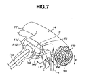
- FIG. 7 is a view similar to FIG. 5B, explaining operation of the deflashing apparatus
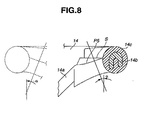
- FIG. 8 is a diagrammatic view for explaining operation of the deflashing apparatus
- FIG. 9 is a fragmentary enlarged view showing the tip of a deflashing blade used in the deflashing apparatus.
- FIG. 10 is a view similar to FIG. 5B, showing a variation of the deflashing blade
- FIG. 11 is a view similar to FIG. 10, explaining operation of the deflashing apparatus.
- FIG. 12 is a sectional view showing a flash supporter.
- a deflashing apparatus 1 which comprises a blade positioning means 2 and a molded article supporting means 3 is arranged in a box-like casing 4 having on the top an opening 4a for loading and unloading of a molded article 14.
- the blade positioning means 2 is constructed, for example, by a six-axis robot, and includes a base 2a, a first arm 2b having a lower end rotatably supported on the base 2a, and a second arm 2c having a base end rotatably supported to an upper end of the first arm 2b.
- a blade moving unit or hand 5 Is mounted to a top end of the second arm 2c.
- the blade moving unit 5 includes a pressing means 7 comprising a guide means 6 and a hydraulic cylinder 7a.
- the guide means 6 includes a guide rail 6a comprising an LM guide horizontally disposed on a base plate 5a of the blade moving unit 5 and a slide member 6b slidably supported on the guide rail 6a.
- a support member 5b is arranged on the slide member 6b, and has an upper portion to which a guide rod 6c extending horizontally is fixed.
- Another end of the guide rod 6c is slidably supported by a guide cylinder 6d provided at an upper portion of a pole 5c having a lower end fixed to the base plate 5a.
- the hydraulic cylinder 7a is arranged parallel below the guide rod 6c.
- the hydraulic cylinder 7a comprises, for example, a low-friction pneumatic cylinder, wherein a piston rod 7c protrudes from a cylinder portion 7b horizontally fixed to the pole 5c, and has a tip connected to the support member 5b through a joint 7d.
- the hydraulic cylinder 7a allows the slide member 6b and the support member 5b to move linearly along the guide rail 6a toward or away from the molded article supporting means 3.
- a vibration generating means 8 is mounted to the support member 5b on the surface opposite to the molded article supporting means 3.
- the vibration generating means 8 includes a pair of parallel links 8a formed out of an elastic plate such as leaf spring.
- the parallel links 8a have one end fixed to the support member 5b through a bracket 8b in such a way as to put their ends on the side of the support member 5b at a higher level, and another end fixed to a cutter mounting member 8d through a bracket 8c.
- a vibration unit 8e having one end mounted to the support member 5b is interposed between the parallel links 8a.
- the vibration unit 8e comprises an electromagnetic vibrator having a predetermined vibration frequency such as 50Hz, and can provide vibration to a deflashing blade 11 as will be described later in the direction parallel to or crossing the direction of travel of the deflashing blade 11 by attracting or releasing a magnetic body 8f attached to the cutter mounting member 8d.
- a turning means 10 comprising a rotary actuator is mounted, with a turning axis 10a facing upward, to the cutter mounting member 8d on the surface opposite to the surface to which the magnetic body 8f is attached.
- a blade-like deflashing blade 11 having a sharp tip is detachably attached to the tip of the turning axis 10a of the turning means 10, and a heating means 12 for heating the deflashing blade 11 is provided in the turning axis 10a.
- the molded article supporting means 3 for supporting the molded article 14 is constructed by a vertically movable and rotatable one-axis numerically controlled (NC) rotary table, and is vertically arranged in the casing 4.
- a roughly disk-like holder 3b is mounted to a vertically movable and rotatable support rod 3a at the tip protruding upward.
- a chuck 3c is arranged in the center of the holder 3b to allow holding of the center portion of the molded article 14 with a flash 14d (see FIG. 5A, for example) to be removed.
- the molded article 14 is a steering wheel body having a spoke 14a of a predetermined shape such as T shape, wherein the whole of a ring-like rim 14b and part of the spoke 14a are covered with a coating layer 14c of synthetic resin such as polyurethane, and the flash 14d produced when forming the coating layer 14c is seen on the outer and inner peripheries of the coating layer 14c.
- the rim 14b is formed like an incomplete round ring.
- a control system controls the blade positioning means 2 and the molded article supporting means 3 to automatically remove the flash 14d from the molded article 14.
- the holder 3b when removing the flash 14d from the molded article 14, the holder 3b is moved upward to the upper position shown by imaginary line, i.e. the position above the opening 4a of the casing 4 provided to secure the safety of an operator, to dispose the molded article 14 on the holder 3b of the molded article supporting means 3 in such a way as to set the rim 14b horizontally. And the center of the molded article 14 is held with the chuck 3c as shown in FIG. 1.
- the blade positioning means 2 is controlled by a control means or sequencer 16 of the control system to move the blade moving unit 5 mounted at the tip of the second arm 2c to the vicinity of the molded article 14, positioning the deflashing blade 11 mounted to the blade moving unit 5 at the deflashing position of the molded article 14.
- the deflashing blade 11 when starting removal of the flash 14d from a point P1 on the molded article 14, the deflashing blade 11 is positioned at the point P1.
- a pressure control valve 17 connected to the pressing means 7 is controlled by the control means 16 to supply air of a predetermined pressure adjusted by a pressure regulating valve 18 to the hydraulic cylinder 7a of the pressing means 7, moving the support member 5b toward the molded article 14 by the pressing means 7 to bring the deflashing blade 11 into contact with the coating layer 14c at the point P1.
- the vibration generating means 8 is operated to vertically vibrate the deflashing blade 11 heated to a predetermined temperature such as 160°C by the heating means 12 such as an electric heater.
- the molded article supporting means 3 is controlled by the control means 16 to rotate the molded article 14 rightward about 1.1 rotation or about 400°.
- the flash 14d produced along the parting line 14e from the point P1 to a point P2 after making one circle therefrom is removed by the deflashing blade 11.
- the pressing means 7 is moved toward the coating layer 14c by the pressure within the hydraulic cylinder 7a, which is lowered accordingly.
- the pressure within the hydraulic cylinder 7a is detected by a pressure sensor 21, which is always provided to the control means 16, so that if the pressure is lowered, the control means 16 controls the pressure control valve 17 to supply air to the hydraulic cylinder 7a until the pressure within the hydraulic cylinder 7a becomes within a predetermined pressure value range.
- the deflashing blade 11 always makes contact with the coating layer 14c at a constant pressure and will not leave from the coating layer 14c, so that even if the molded article 14 is varied dimensionally, or the coating layer 14c contracts in the circumferential direction, or the rim 14b is an incomplete round, complete removal of the flash 14d and uniformity of the deflashed surface can be achieved, obtaining an excellent finished surface.
- the pressure within the hydraulic cylinder is increased, which is, however, corrected by the pressure control valve 17 through the control means 16 to be within a predetermined pressure value range, preventing the deflashing blade 11 from biting the coating layer 14c, thus obtaining an excellent finished surface in the same way as described above.
- the blade positioning means 2 and the molded article supporting means 3 are controlled by the control means 16 to position the deflashing blade 11 so as to make contact with a point P3 on the coating layer 14c.
- the parting line 14e of the spoke 14a is inclined as shown in FIG. 7, so that the deflashing blade 11 is positioned to extend downward of an imaginary line S shown in FIG. 8, which is a direct extension of the parting line 14e of the rim 14b.
- the blade positioning means 2 is controlled by the control means 16 to move the deflashing blade 11 along the parting line 14e so as to remove the flash 14d.
- a portion of the molded article 14 from the rim 14b to the spoke 14a is formed like a small-diameter arc.
- the pressure control valve 19 connected to the turning means 10 is controlled by the control means 16 to move the deflashing blade 11 along the spoke 14a and a curve of the inner periphery of the rim 4b in the vicinity thereof.
- the blade positioning means 2 is controlled by the control means 16 to move the deflashing blade 11 to a point P7 for stopping.
- the molded article 14 is rotated clockwise by the molded article supporting means 3 to remove the flash 14d to a point P8.
- the blade positioning means 2 is controlled by the control means 16 to remove the flash 14d from the point PB to a point P9 in the same way as removal from the point P4 to the point P5.
- Similar operation is repeatedly carried out to remove the flash 14d from a point P11 to a point P12 and from the point P12 to a point P13.
- the deflashing blade 11 is reversed in the cutting direction by the fuming means 10, and simultaneously, it is moved to the point P4 by the blade positioning means 2.
- the molded article 14 is rotated counterclockwise by the molded article supporting means 3 to carry out relative movement along the coating layer 14c already subjected to deflashing operation from the point P4 to the point P3 for refinishing of the deflashed surface.
- Similar operation to that when removing the flash 14d by clockwise rotation of the molded article 14 is carried out to remove the remaining flash 14d from the point P3 to the point P6, from the point P12 to the point P11, from the point P11 to a point P14, from the point P8 to the point P7, and finally from the point P7 to the point P10. Then, the deflashing blade 11 is retuned by the blade positioning means 2 to the home position where it is away from the molded article 14, thus completing the deflashing process of the molded article 14.
- the flash 14d produced on the coating layer 14c of the molded article 14 is removed automatically. Due to deflashing operation carried out twice, i.e. during clockwise rotation of the molded article 14 and during counterclockwise rotation thereof in addition to seamless coating, the inner peripheral face of the coating layer 14c can be provided with a smoother deflashed surface.
- the flash 14d produced on the molded article 14 positionally varies in thickness due to the configuration of the mold. Specifically, referring to FIG. 5A, the thickness is 1.5-2.0mm at a resin injecting portion or gate 14f, 1.0-1.2mm at an overflow portion, and 0.2-0.4mm at other portion (general portion).
- the flashes exist in the form of a small-thickness flash at the general portion and a different-thickness flash at the gate 14f and the overflow portion, so that, referring to FIG. 11, when deflashing operation is carried out from left to right as shown by arrow, the small-thickness flash 14d may be broken by the weight of the large-thickness flash 14d at the gate 14f, which can cause incomplete elimination of the flash 14d. The remaining flash 14d should be eliminated manually.
- a flash supporter 3d is arranged adjacent to the holder 3b of the molded article supporting means 3 so as to support the flash 14d from below at the gate 14f and that at the overflow portion.
- Loading of the molded article 14 onto the deflashing apparatus 1 is carried out by disposing the molded article 14 on the holder 3b of the molded article supporting means 3 in such a way as to set the rim 14b horizontally, and by holding the center of the molded article 14 with the chuck 3c.
- the molded article 14 is steering wheel body S, and the rim 4b cannot always horizontally be set on the holder 3b due to welding distortion at a core bar and a boss, stable flash finishing may not be carried out.
- the center or boss of the molded article 14 is held with the chuck 3c, which is then moved downward so as to set the rim 14b on the holder 3b horizontally. This allows secure positioning of the molded article 14 at the rim 14b, obtaining correction of face and center deflections due to welding distortion, resulting in stable flash finishing.
- the hydraulic cylinder 7a constituting the pressing means 7 which brings the deflashing blade 11 into contact with the coating layer 14c is controlled at a relatively low air pressure of 0.5-1.5kgf/cm 2 , and it includes a low-friction cylinder, achieving improved response-ability when the deflashing blade 11 is moved along the surface of the coating layer 14c.
- the molded article supporting means 3 carries out absolutely simple rotating motion, and the blade positioning means 2 carries out relatively complicated motion, net movement of the deflashing blade 11 provided to the blade positioning means 2 is limited to a very narrow range corresponding to only a fraction of the size of the molded article 14.
- the deflashing blade 11 always operates on the right side of the molded article or steering wheel body 14 as viewed in FIG. 8 with respect to the center of rotation thereof. Therefore, the deflashing blade 11 only needs to have always a deflection angle in the positive direction, such as angle ⁇ . This ensures operation of the deflashing blade 11 without large operative difference even if a slight difference exists between the inclination of the horizontal spoke 14a and the vertical spoke 14a, for example, enabling teaching of the blade positioning means 2 in accordance with essentially common operation.
- the deflashing blade 11 for operation of the deflashing blade 11 on the opposite side of the spoke 14a, i.e. from the point P4 to the point P5, the deflashing blade 11 only needs to have a deflection angle of ⁇ .
- the deflashing blade 11 is formed, for example, out of BM-1P (material: SKS, manufactured by NT Cutter Co.) which is a triangular blade with edge angle of about 20° or a typical razor blade (material: so-called Gin Roku) with edge angle of 14.5°.
- BM-1P material: SKS, manufactured by NT Cutter Co.
- Gin Roku material: so-called Gin Roku
- the deflashing efficiency is generally enhanced by applying vibration to the deflashing blade 11.
- application of vibration is carried out by using the electromagnetic vibration generating means 8, wherein the amplitude of vibration is in the range of about 1 to 0.001mm, and the frequency is in the range of about 10 to 100KHz (50Hz in this embodiment).
- higher frequency may be applied by using an ultrasonic vibration generating means.
- Table 1 shows the relationship between the edge shape of the deflashing blade 11 (see FIG. 9) and the frequency and amplitude of vibration to be applied to the deflashing blade 11, wherein the means for generating vibration of 50Hz includes electromagnetic vibrator, the means for generating vibration of 675Hz includes pneumatic vibrator, and the means for generating vibration of 22,000Hz frequency includes ultrasonic generator. Case No.
- the number of molded articles 14 which can be worked by one deflashing blade 11 is greatly increased, resulting in decreased consumption of the deflashing blade 11.
- the deflashing blade 11 is replaced manually with the deflashing apparatus 1 stopped, and it is vibrated for deflashing operation, resulting in enhanced availability of the apparatus.
- the number of apparatus controlled by an operator can be increased, leading to an improvement in labor cost.
- the number of replacements of the deflashing blade 11 can be reduced, there is no need to consider automatic replacement of the deflashing blade 11, leading to a reduction in manufacturing cost of the apparatus.
- so-called passive control is adopted wherein a force of the coating layer 14c for pushing back the deflashing blade 11 is captured as an inner-pressure change within the hydraulic cylinder 7a for stabilization.
- active control may be adopted wherein a pattern of an inner-pressure change is preprogrammed as a standard value to supply or discharge air in accordance with motion of the molded article 14.
- the standard value is set to be smaller than a required value, and an insufficient pressure is obtained by detecting a difference therebetween to achieve a constant pressure.
- the rim 14b of the steering wheel or molded article 14 is an incomplete round with slight variation in diameter in the circumferential direction, which is a trend specific to the product resulting from the design based on the ergonomics.
- Addition of the learning function allows statistic processing of a dispersion in shape of the molded articles 14 and real-time correction of its standard value. Therefore, the use of active control can provide a secondary effect that the working accuracy enhances as the quantity of production increases.
- the single-edged deflashing blade 11 is used as shown in FIG. 5B.
- a double-edged deflashing blade 11 may be used as shown in FIG. 10.
- the deflashing blade 11 when removing the flash 14d of the molded article 14, the deflashing blade 11 is moved in two distinct movements from the point P3 to the point P4 and from the point P4 to the point P5. Alternatively, the deflashing blade 11 may be moved in single and continuous movement from the point P3 through the point P4 to the point P5. Moreover, when fuming the molded article 14 to the point P4, the flash 14d can be removed with the deflashing blade 11 stopped, and from the point P4 to the point P5, it can be removed by operating the blade positioning means 2 in accordance with signals for operation of the molded article supporting means 3 which is being rotated.
- the deflashing apparatus 1 may further include a grinding means for grinding the deflashing blade 11.
- a grinding means for grinding the deflashing blade 11 This allows preservation of the sharpness of the deflashing blade 11, resulting in higher-quality molded article 14 with no residual flash 14d.
- preservation of the sharpness of the deflashing blade 11 can be preserved for the long term without replacement, resulting in elongated cycle of replacement. This contributes to an improvement in productivity due to no stopping of the deflashing apparatus 1 for replacement of the deflashing blade 11.
- alternate execution of the deflashing process of the molded article 14 and the grinding process of the deflashing blade 11 allows further improvement in productivity.
- the hydraulic cylinder 7a serves to press the deflashing blade 11 against the molded article 14, the inner pressure of which is detected to obtain a predetermined pressing force.
- an electric actuator including, for example, a servomotor may be used with a distortion sensor, wherein drive of the former is controlled in accordance with electric signals of the latter.
- the present invention allows removal of the flash by moving the blade along the periphery of the molded article, leading to easy and secure removal of the flash produced on the molded article even with the complicated shape. Moreover, removal is possible without using a blade of the particular shape, leading to complete elimination of the flash and reduction in running cost
- Removal of the flash can be carried out by moving the molded article with respect to the blade by the supporting device, resulting in efficient and short-time operation.
- Such deflashing operation ensures an excellent deflashed surface of the molded article, and is thus applicable, preferably, to molded articles to be gripped during application, such as a steering wheel, due to no evocation of uncomfortable feel.
- the blade can securely be brought into contact with the flash on the molded article by the pressing device, producing no residual flash.
- the hydraulic cylinder is in the form of a low-friction pneumatic cylinder, resulting in improved fellow-ability of the blade with respect to the molded article surface with flash produced.
- the blade comprises a single-edged blade and a double-edged blade
- the moving unit moves the blade in one of a first direction and a second direction opposite to the first direction with respect to the molded article.
- the hydraulic pressure within the hydraulic cylinder is detected to feedback control the hydraulic cylinder in such a way that the hydraulic pressure is within a predetermined value range. This allows the blade to be pressed against the molded article at an appropriate pressure by the hydraulic cylinder, preventing incomplete elimination of the flash and excessively deep cutting of the molded article by the blade, leading to achievement of an excellent finished surface and reduction in occurrence of a defective due to deep cutting of the molded article.
- the hydraulic pressure is changed using a program prepared in accordance with a shape of the molded article, wherein the hydraulic cylinder is controlled to correct by the hydraulic pressure a difference between the changed hydraulic pressure and the detected hydraulic pressure.
- the molded article has a circular portion, wherein the supporting device rotates the molded article about a center of the circular portion to carry out relative movement of the blade. This allows simple and rational motion of the molded article through the circular portion, leading to efficient removal of the flash.
- the apparatus further comprises a vibration device mounted to the moving unit for providing vibration to the blade, wherein vibration is carried out in one of directions parallel to and crossing a direction of travel of the blade.
- the apparatus further comprises a turning device mounted to the moving unit for turning the blade in a direction of travel of the blade, which contributes to easy turning of the blade.
- the apparatus further comprises a heating device for heating the blade and a supporter arranged adjacent to the supporting device for supporting the flash from below.
- the heating device contributes enhancement of the deflashing efficiency
- the supporter contributes to prevention of the small-thickness flash from being broken by the weight of the large-thickness flash, and thus prevention of incomplete elimination of the flash.
Landscapes
- Physics & Mathematics (AREA)
- Thermal Sciences (AREA)
- Moulds For Moulding Plastics Or The Like (AREA)
- Processing And Handling Of Plastics And Other Materials For Molding In General (AREA)
Applications Claiming Priority (6)
| Application Number | Priority Date | Filing Date | Title |
|---|---|---|---|
| JP2001186951A JP2003001639A (ja) | 2001-06-20 | 2001-06-20 | 成形品のバリ除去装置 |
| JP2001186979A JP2003001640A (ja) | 2001-06-20 | 2001-06-20 | 成形品のバリ除去装置 |
| JP2001186993 | 2001-06-20 | ||
| JP2001186979 | 2001-06-20 | ||
| JP2001186951 | 2001-06-20 | ||
| JP2001186993A JP2003001641A (ja) | 2001-06-20 | 2001-06-20 | 成形品のバリ除去装置 |
Publications (1)
| Publication Number | Publication Date |
|---|---|
| EP1270166A1 true EP1270166A1 (de) | 2003-01-02 |
Family
ID=27346986
Family Applications (1)
| Application Number | Title | Priority Date | Filing Date |
|---|---|---|---|
| EP02013733A Withdrawn EP1270166A1 (de) | 2001-06-20 | 2002-06-20 | Vorrichtung zum Entgraten |
Country Status (2)
| Country | Link |
|---|---|
| US (1) | US20030021861A1 (de) |
| EP (1) | EP1270166A1 (de) |
Cited By (6)
| Publication number | Priority date | Publication date | Assignee | Title |
|---|---|---|---|---|
| NL1031358C2 (nl) * | 2006-03-13 | 2007-09-14 | Paperfoam B V | Inrichting en werkwijze voor het uitnemen van producten uit een matrijs. |
| EP2226172A4 (de) * | 2007-12-27 | 2011-08-24 | Nihon Shoryoku Kikai Co Ltd | Entgratsystem, entgratvorrichtung und schneidmesser |
| CN105592988A (zh) * | 2013-10-11 | 2016-05-18 | 日本省力机械株式会社 | 切割刀具和加工装置 |
| KR101842641B1 (ko) | 2016-06-10 | 2018-03-29 | 주식회사 디케이엘 | 패널 프레임용 버 제거 장치 |
| CN109732826A (zh) * | 2019-01-21 | 2019-05-10 | 安徽皖精模具科技有限公司 | 一种塑料件生产用去飞边装置 |
| CN113334455A (zh) * | 2021-08-09 | 2021-09-03 | 南通市春晖箱包有限公司 | 一种用于箱包生产加工的修边设备及修边方法 |
Families Citing this family (8)
| Publication number | Priority date | Publication date | Assignee | Title |
|---|---|---|---|---|
| US8277282B2 (en) * | 2005-10-04 | 2012-10-02 | Nihon Shoryoku Kikai Co., Ltd. | Ultrasonic trimming apparatus and ultrasonic trimming method |
| US7867426B2 (en) * | 2006-03-23 | 2011-01-11 | Ziran Bruce H | Method of forming a temporary implant |
| JP4804324B2 (ja) * | 2006-12-15 | 2011-11-02 | 富士通株式会社 | ペースト印刷装置およびペースト印刷方法 |
| TWI426015B (zh) * | 2007-12-31 | 2014-02-11 | Nihon Shoryoku Kikai Co Ltd | 毛邊移除系統及毛邊移除裝置 |
| CN103038039B (zh) * | 2010-08-09 | 2015-01-21 | 日本省力机械株式会社 | 刮板式去毛刺装置 |
| JP4955823B1 (ja) * | 2011-04-05 | 2012-06-20 | 日本省力機械株式会社 | ワーク取り出し仕上げ装置 |
| TW202126408A (zh) | 2020-01-02 | 2021-07-16 | 財團法人工業技術研究院 | 毛邊清除裝置 |
| CN111976069A (zh) * | 2020-08-19 | 2020-11-24 | 湖州万佑远程科技有限公司 | 一种交通工具方向盘处理加工装置及加工方法 |
Citations (6)
| Publication number | Priority date | Publication date | Assignee | Title |
|---|---|---|---|---|
| JPS57187235A (en) * | 1981-05-13 | 1982-11-17 | Naito Seisakusho:Kk | Flash removing apparatus of molded product |
| EP0295458A2 (de) * | 1987-05-22 | 1988-12-21 | Nihon Plast Co., Ltd. | Vorrichtung zum Entfernen von Graten von Gussprodukten |
| US4836722A (en) * | 1985-08-10 | 1989-06-06 | Toyoda Gosei Co., Ltd. | Method and apparatus for removing flash of polymeric molded products |
| US4892018A (en) * | 1985-09-03 | 1990-01-09 | Allied-Signal Inc. | Deflashing method and apparatus |
| JPH0732212A (ja) * | 1993-07-22 | 1995-02-03 | Horie Metal Co Ltd | バリ切削装置 |
| US6027288A (en) * | 1997-01-09 | 2000-02-22 | Senjo Seiki Corporation | Working apparatus for chamfering workpieces |
-
2002
- 2002-06-20 US US10/175,347 patent/US20030021861A1/en not_active Abandoned
- 2002-06-20 EP EP02013733A patent/EP1270166A1/de not_active Withdrawn
Patent Citations (6)
| Publication number | Priority date | Publication date | Assignee | Title |
|---|---|---|---|---|
| JPS57187235A (en) * | 1981-05-13 | 1982-11-17 | Naito Seisakusho:Kk | Flash removing apparatus of molded product |
| US4836722A (en) * | 1985-08-10 | 1989-06-06 | Toyoda Gosei Co., Ltd. | Method and apparatus for removing flash of polymeric molded products |
| US4892018A (en) * | 1985-09-03 | 1990-01-09 | Allied-Signal Inc. | Deflashing method and apparatus |
| EP0295458A2 (de) * | 1987-05-22 | 1988-12-21 | Nihon Plast Co., Ltd. | Vorrichtung zum Entfernen von Graten von Gussprodukten |
| JPH0732212A (ja) * | 1993-07-22 | 1995-02-03 | Horie Metal Co Ltd | バリ切削装置 |
| US6027288A (en) * | 1997-01-09 | 2000-02-22 | Senjo Seiki Corporation | Working apparatus for chamfering workpieces |
Non-Patent Citations (2)
| Title |
|---|
| PATENT ABSTRACTS OF JAPAN vol. 007, no. 031 (M - 192) 8 February 1983 (1983-02-08) * |
| PATENT ABSTRACTS OF JAPAN vol. 1995, no. 05 30 June 1995 (1995-06-30) * |
Cited By (8)
| Publication number | Priority date | Publication date | Assignee | Title |
|---|---|---|---|---|
| NL1031358C2 (nl) * | 2006-03-13 | 2007-09-14 | Paperfoam B V | Inrichting en werkwijze voor het uitnemen van producten uit een matrijs. |
| EP2226172A4 (de) * | 2007-12-27 | 2011-08-24 | Nihon Shoryoku Kikai Co Ltd | Entgratsystem, entgratvorrichtung und schneidmesser |
| US8806999B2 (en) | 2007-12-27 | 2014-08-19 | Nihon Shoryoku Kikai Co., Ltd. | Deburring system, deburring apparatus and cutter blade |
| CN105592988A (zh) * | 2013-10-11 | 2016-05-18 | 日本省力机械株式会社 | 切割刀具和加工装置 |
| KR101842641B1 (ko) | 2016-06-10 | 2018-03-29 | 주식회사 디케이엘 | 패널 프레임용 버 제거 장치 |
| CN109732826A (zh) * | 2019-01-21 | 2019-05-10 | 安徽皖精模具科技有限公司 | 一种塑料件生产用去飞边装置 |
| CN109732826B (zh) * | 2019-01-21 | 2020-12-01 | 安徽皖精模具科技有限公司 | 一种塑料件生产用去飞边装置 |
| CN113334455A (zh) * | 2021-08-09 | 2021-09-03 | 南通市春晖箱包有限公司 | 一种用于箱包生产加工的修边设备及修边方法 |
Also Published As
| Publication number | Publication date |
|---|---|
| US20030021861A1 (en) | 2003-01-30 |
Similar Documents
| Publication | Publication Date | Title |
|---|---|---|
| EP1270166A1 (de) | Vorrichtung zum Entgraten | |
| US4995286A (en) | Apparatus for removing flash from molded products | |
| CA3002964C (en) | Machine and method for forming articles | |
| US4118846A (en) | Burnishing attachment | |
| JP2004504166A (ja) | 超音波を利用したマイクロバニシ仕上げ装置 | |
| US3675706A (en) | Tire buffing machine | |
| CN100395102C (zh) | 轮胎的生产方法和轮胎成型机 | |
| US5575708A (en) | Belt grinding machine and method for forming cutting edges on surgical instruments | |
| JPH06262431A (ja) | バリ取り装置 | |
| US3704554A (en) | Lens processing machine with movable workpiece spindle | |
| JP2003001639A (ja) | 成形品のバリ除去装置 | |
| JP2003001640A (ja) | 成形品のバリ除去装置 | |
| JP2003001641A (ja) | 成形品のバリ除去装置 | |
| JP2003311752A (ja) | 樹脂成形品のバリ除去装置 | |
| JPH04338530A (ja) | 自動スピュー・トリミング方法およびそれに用いる装置 | |
| EP1343613B1 (de) | Vorrichtung und verfahren zur randbearbeitung einer kontaktlinse | |
| JP2010137432A (ja) | プラスチック成形品の仕上げ装置 | |
| JPH06134771A (ja) | プラスチック成形品のばり取り装置 | |
| JP2531034B2 (ja) | 薄板の成形金型 | |
| JPS6052892B2 (ja) | ワイヤカツト放電加工方法 | |
| EP0459158A2 (de) | Werkzeugmaschine zum Schleifen von Flächen | |
| JP2004058281A (ja) | タイヤモールドの製作方法及び製作装置 | |
| JP3786668B2 (ja) | スリッター丸刃の研削加工装置 | |
| JP2710895B2 (ja) | 線材のコイリング方法 | |
| JPH05318236A (ja) | 金属製洋食器の製造方法および金属製洋食器並びに半製品 |
Legal Events
| Date | Code | Title | Description |
|---|---|---|---|
| PUAI | Public reference made under article 153(3) epc to a published international application that has entered the european phase |
Free format text: ORIGINAL CODE: 0009012 |
|
| 17P | Request for examination filed |
Effective date: 20020620 |
|
| AK | Designated contracting states |
Kind code of ref document: A1 Designated state(s): AT BE CH CY DE DK ES FI FR GB GR IE IT LI LU MC NL PT SE TR |
|
| AX | Request for extension of the european patent |
Free format text: AL;LT;LV;MK;RO;SI |
|
| 17Q | First examination report despatched |
Effective date: 20030320 |
|
| AKX | Designation fees paid |
Designated state(s): DE ES FR GB |
|
| STAA | Information on the status of an ep patent application or granted ep patent |
Free format text: STATUS: THE APPLICATION IS DEEMED TO BE WITHDRAWN |
|
| 18D | Application deemed to be withdrawn |
Effective date: 20040812 |