EP1270167B1 - Verfahren zur Herstellung eines Gerätegehäuses - Google Patents
Verfahren zur Herstellung eines Gerätegehäuses Download PDFInfo
- Publication number
- EP1270167B1 EP1270167B1 EP02009637A EP02009637A EP1270167B1 EP 1270167 B1 EP1270167 B1 EP 1270167B1 EP 02009637 A EP02009637 A EP 02009637A EP 02009637 A EP02009637 A EP 02009637A EP 1270167 B1 EP1270167 B1 EP 1270167B1
- Authority
- EP
- European Patent Office
- Prior art keywords
- conducting track
- support plate
- track film
- plastic
- electronic components
- Prior art date
- Legal status (The legal status is an assumption and is not a legal conclusion. Google has not performed a legal analysis and makes no representation as to the accuracy of the status listed.)
- Expired - Lifetime
Links
Images
Classifications
-
- H—ELECTRICITY
- H05—ELECTRIC TECHNIQUES NOT OTHERWISE PROVIDED FOR
- H05K—PRINTED CIRCUITS; CASINGS OR CONSTRUCTIONAL DETAILS OF ELECTRIC APPARATUS; MANUFACTURE OF ASSEMBLAGES OF ELECTRICAL COMPONENTS
- H05K5/00—Casings, cabinets or drawers for electric apparatus
- H05K5/06—Hermetically-sealed casings
- H05K5/065—Hermetically-sealed casings sealed by encapsulation, e.g. waterproof resin forming an integral casing, injection moulding
-
- B—PERFORMING OPERATIONS; TRANSPORTING
- B29—WORKING OF PLASTICS; WORKING OF SUBSTANCES IN A PLASTIC STATE IN GENERAL
- B29C—SHAPING OR JOINING OF PLASTICS; SHAPING OF MATERIAL IN A PLASTIC STATE, NOT OTHERWISE PROVIDED FOR; AFTER-TREATMENT OF THE SHAPED PRODUCTS, e.g. REPAIRING
- B29C45/00—Injection moulding, i.e. forcing the required volume of moulding material through a nozzle into a closed mould; Apparatus therefor
- B29C45/14—Injection moulding, i.e. forcing the required volume of moulding material through a nozzle into a closed mould; Apparatus therefor incorporating preformed parts or layers, e.g. injection moulding around inserts or for coating articles
- B29C45/14639—Injection moulding, i.e. forcing the required volume of moulding material through a nozzle into a closed mould; Apparatus therefor incorporating preformed parts or layers, e.g. injection moulding around inserts or for coating articles for obtaining an insulating effect, e.g. for electrical components
-
- E—FIXED CONSTRUCTIONS
- E05—LOCKS; KEYS; WINDOW OR DOOR FITTINGS; SAFES
- E05B—LOCKS; ACCESSORIES THEREFOR; HANDCUFFS
- E05B81/00—Power-actuated vehicle locks
- E05B81/54—Electrical circuits
-
- E—FIXED CONSTRUCTIONS
- E05—LOCKS; KEYS; WINDOW OR DOOR FITTINGS; SAFES
- E05B—LOCKS; ACCESSORIES THEREFOR; HANDCUFFS
- E05B85/00—Details of vehicle locks not provided for in groups E05B77/00 - E05B83/00
- E05B85/02—Lock casings
-
- H—ELECTRICITY
- H05—ELECTRIC TECHNIQUES NOT OTHERWISE PROVIDED FOR
- H05K—PRINTED CIRCUITS; CASINGS OR CONSTRUCTIONAL DETAILS OF ELECTRIC APPARATUS; MANUFACTURE OF ASSEMBLAGES OF ELECTRICAL COMPONENTS
- H05K3/00—Apparatus or processes for manufacturing printed circuits
- H05K3/0058—Laminating printed circuit boards onto other substrates, e.g. metallic substrates
- H05K3/0061—Laminating printed circuit boards onto other substrates, e.g. metallic substrates onto a metallic substrate, e.g. a heat sink
-
- B—PERFORMING OPERATIONS; TRANSPORTING
- B29—WORKING OF PLASTICS; WORKING OF SUBSTANCES IN A PLASTIC STATE IN GENERAL
- B29L—INDEXING SCHEME ASSOCIATED WITH SUBCLASS B29C, RELATING TO PARTICULAR ARTICLES
- B29L2031/00—Other particular articles
- B29L2031/34—Electrical apparatus, e.g. sparking plugs or parts thereof
- B29L2031/3481—Housings or casings incorporating or embedding electric or electronic elements
-
- H—ELECTRICITY
- H05—ELECTRIC TECHNIQUES NOT OTHERWISE PROVIDED FOR
- H05K—PRINTED CIRCUITS; CASINGS OR CONSTRUCTIONAL DETAILS OF ELECTRIC APPARATUS; MANUFACTURE OF ASSEMBLAGES OF ELECTRICAL COMPONENTS
- H05K1/00—Printed circuits
- H05K1/18—Printed circuits structurally associated with non-printed electric components
- H05K1/189—Printed circuits structurally associated with non-printed electric components characterised by the use of flexible or folded printed circuits
-
- H—ELECTRICITY
- H05—ELECTRIC TECHNIQUES NOT OTHERWISE PROVIDED FOR
- H05K—PRINTED CIRCUITS; CASINGS OR CONSTRUCTIONAL DETAILS OF ELECTRIC APPARATUS; MANUFACTURE OF ASSEMBLAGES OF ELECTRICAL COMPONENTS
- H05K2203/00—Indexing scheme relating to apparatus or processes for manufacturing printed circuits covered by H05K3/00
- H05K2203/13—Moulding and encapsulation; Deposition techniques; Protective layers
- H05K2203/1305—Moulding and encapsulation
- H05K2203/1327—Moulding over PCB locally or completely
-
- H—ELECTRICITY
- H05—ELECTRIC TECHNIQUES NOT OTHERWISE PROVIDED FOR
- H05K—PRINTED CIRCUITS; CASINGS OR CONSTRUCTIONAL DETAILS OF ELECTRIC APPARATUS; MANUFACTURE OF ASSEMBLAGES OF ELECTRICAL COMPONENTS
- H05K3/00—Apparatus or processes for manufacturing printed circuits
- H05K3/38—Improvement of the adhesion between the insulating substrate and the metal
- H05K3/386—Improvement of the adhesion between the insulating substrate and the metal by the use of an organic polymeric bonding layer, e.g. adhesive
Definitions
- the invention relates to a method for the production of housing parts made of plastic, which are provided with flexible conductor sheets for connecting electrical or electronic components.
- the placement of the conductor film outside of the plastic housing can be done relatively inexpensively, because the solder paste for all solder points in a single operation can be applied almost simultaneously by doctoring the solder paste through an applied mask on the conductor film.
- the already equipped with electronic components trace film in the manufacture of the plastic housing must be back-injected with hot plastic under high pressure.
- the sensitive electronic components can be destroyed either by overheating or by mechanical pressure.
- the object of the invention is to provide a method for the production of device housing parts made of plastic, which allows the injection-back of provided with electronic components printed circuit films.
- the manufacturing method according to the invention has the advantage that the electronic components are applied to the printed circuit film with inexpensive standard methods and the printed circuit board with electronic components can still be connected to the device housing or the device housing part during the injection molding process, without destroying the sensitive electronic components ,
- the provided with the electronic components region of the conductor foil coincides during injection molding with a recess of the injection mold, wherein the components protrude into this recess.
- the recess of the pointed tool is sealed during the injection process to the side, so that a cavity is formed into which no plastic can penetrate during injection molding.
- the "lid" for closing the recess in the injection mold is formed by the support plate fastened on the back of the strip conductor film.
- the support plate also absorbs the pressure of the injected plastic compound, so that it does not load on the conductor foil with the sensitive components. Without the support plate, the components could break or tear the conductor tracks in the conductor foil.
- the support plate also keeps the heat of the hot plastic mass substantially from the sensitive electronic components, so that they are not heated inadmissible.
- the components are fixed on one side of the conductor film by soldering, wherein a solder paste is applied by means of doctoring by a mask applied to the conductor film prior to assembly of the components.
- an aluminum plate as a support plate has the advantage that the heat introduced by the hot plastic mass is buffered and thus temperature peaks in the sensitive electronic components can be avoided.
- the aluminum plate takes over during subsequent operation of the device, the task of a cooling plate for dissipating the heat generated in the electronic components.
- the cooling effect can be further improved in that the support plate is provided on its side facing away from the conductor foil with cooling fins.
- the concept of the invention is essentially already contained in a conductor foil which is equipped with electronic components on one side and on the other side has at least one support plate covering a portion of the conductor foil which stiffenes at least one region of the conductor foil fitted with electronic components.
- a conductor sheet film thus configured according to the invention in conjunction with known production methods for device housing parts made of plastic, leads to the same result as the method according to one of claims 1 to 5.
- the scope of the invention also includes a device housing or a device housing part made of plastic, which has a conductor foil with one of the above-mentioned feature combinations, in which the conductor foil is at least partially back-injected or molded with plastic.
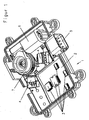
- a housing part 1 of an actuating unit for a central locking system of a motor vehicle can be seen.
- the Housing part 1 is made of plastic and has been produced by injection molding.
- a conductor foil 2 which is equipped with electronic components 3, poured into the housing part 1.
- further electrical components, such as switches 4, a plug 5 and an electric motor have been installed in the housing part 1.
- a worm gear 7 can be seen.
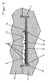
- the conductor foil 2 is provided on its back with an aluminum plate 8, which is glued to the conductor foil 2. Serving as a support plate aluminum plate 8 is enclosed by its narrow sides 9 forth from the plastic mass 10 of the housing part 1.
- the flexible conductor foil 2 is provided with solder paste by applying to the conductor foil 2 a mask, not shown, through which the solder paste is applied by means of doctoring at the desired locations.
- the electronic components 3 are applied and soldered.
- the aluminum plate 8 is glued as a support plate on the back of the conductor foil 2, wherein the lateral extent of the aluminum plate 8 sweeps over the entire equipped with electronic components 3 area of the conductor foil 2 and can support.
- a recess 13 is provided, which is arranged so that the electronic components 3 can protrude into the recess 13.
- the recess 13 on the position of the aluminum plate 8 such matched, that the recess 13 can be completely covered by the underlying aluminum plate 8.
- the two tool parts 11 and 12 are placed on each other and thus closed the injection mold.
- the aluminum plate 8 and the overlying conductor foil are pressed against the edge region 14 of the tool part 12 surrounding the recess 13, so that the recess 13 is firmly closed. This prevents the penetration of hot plastic mass in the cavity formed by the recess 13 and the conductor foil 2 with the aluminum plate 8, and thus also the contact of the hot plastic mass 10 with the sensitive electronic components 3.
- the hot plastic mass 10 is in the Injection tool 11, 12, pressed, wherein the conductor foil 2 is partially encapsulated on its back. Also, the narrow sides 9 of the aluminum plate 8 are encapsulated.
- the invention also includes such embodiments in which the entire back 15 of the aluminum plate 8 is overmolded with plastic compound 10.
- the aluminum plate 8 supports in its function as a support plate from the high pressure of the plastic mass 10 eingpitzten from, so that it can not be harmful to the electronic components 3 act. After solidification of the plastic mass 10, the housing part 1 from the injection mold 11, 12, are removed.
- the heat generated in the electronic components 3 can be efficiently dissipated by the adjoining aluminum plate 8.
- the heat capacity of the aluminum plate 8 alone will be sufficient to absorb the excess heat.
- the aluminum plate 8 In continuous operation, the aluminum plate 8 must serve as a cooling plate.
- an embodiment in which the back side 15 of the aluminum plate 8 is not recommended is encapsulated by plastic compound 10. The heat can then be effectively dissipated by passing past the back 15 air. The cooling effect can be improved by not shown cooling fins on the back 15 of the aluminum plate 8.
Landscapes
- Engineering & Computer Science (AREA)
- Manufacturing & Machinery (AREA)
- Microelectronics & Electronic Packaging (AREA)
- Mechanical Engineering (AREA)
- Injection Moulding Of Plastics Or The Like (AREA)
Description
- Die Erfindung betrifft ein Verfahren zur Herstellung von Gehäuseteilen aus Kunststoff, die mit flexiblen Leiterbahnfolien zur Verbindung elektrischer oder elektronischer Bauteile versehen sind.
- Bei der Herstellung von elektrischen Geräten müssen die einzelnen elektrischen oder elektronischen Bauteile elektrisch miteinander verbunden werden. Um den damit verbundenen Fertigungsaufwand zu reduzieren, ist es bekannt, elektrische Leitungen als Stanzteile auszuführen, die bei der Herstellung von Kunststoffgehäusen in diese integriert werden. Beim nachfolgenden Einbau elektronischer oder elektrischer Bauteile wird die elektrische Verbindung zwischen diesen ohne zusätzlichen Aufwand hergestellt. Die Ausführung der elektrischen Verbindungen als Stanzteile hat jedoch den Nachteil, dass eventuell später notwendige Änderungen der elektrischen Verbindungen mit Änderungen der relativ kostspieligen Stanzwerkzeuge verbunden und somit aufwendig und unrentabel sind.
- Es ist auch bekannt, elektrische Drähte oder starre Leiterbahnen durch flexible Leiterbahnfolien zu ersetzen, die bei der Herstellung des Kunststoffgehäuses in dieses integriert werden, indem die Leiterbahn während des Spritzgußverfahrens hinterspritzt wird. Die hinterspritzte Leiterbahnfolie ist somit im Kunststoffgehäuse fixiert und stellt nach Einsetzen der elektrischen oder elektronischen Bauteile die elektrische Verbindung zwischen diesen her. Dieses Verfahren funktioniert solange zufriedenstellend, als die flexiblen Leiterbahnfolien tatsächlich nur Leiterbahnen enthalten. Zunehmend wird es aber erforderlich, die flexiblen Leiterbahnfolien mit weiteren elektronischen Bauteilen zu bestücken.
- Das nachträgliche Bestücken der bereits mit dem Kunststoffgehäuse verbundenen Leiterbahnfolien hat jedoch den Nachteil, dass das Verlöten der elektronischen Bauteile auf der Leiterbahnfolie relativ aufwendig und kostenintensiv ist, weil die Lotpaste durch Dispensen Punkt für Punkt aufgetragen werden muss.
- Die Bestückung der Leiterbahnfolie außerhalb des Kunststoffgehäuses kann relativ kostengünstig geschehen, weil die Lotpaste für alle Lötpunkte in einem einzigen Arbeitsgang fast gleichzeitig durch Rakeln der Lotpaste durch eine aufgelegte Maske hindurch auf die Leiterbahnfolie aufgebracht werden kann. Allerdings muss dann die bereits mit elektronischen Bauteilen bestückte Leiterbahnfolie bei der Herstellung des Kunststoffgehäuses mit unter hohem Druck stehendem heißen Kunststoff hinterspritzt werden. Dabei können die empfindlichen elektronischen Bauteile entweder durch Überhitzung oder durch den mechanischen Druck zerstört werden.
- Aufgabe der Erfindung ist es, ein Verfahren zur Herstellung von Gerätegehäuseteilen aus Kunststoff anzugeben, welches das Hinterspritzen von mit elektronischen Bauteilen versehenen Leiterbahnfolien ermöglicht.
- Diese Aufgabe wird erfindungsgemäß durch ein Verfahren gelöst, das die folgenden Verfahrensschritte umfaßt:
- Bestücken einer Seite der Leiterbahnfolie mit elektronischen Bauteilen sowie Anbringen von mindestens einer einen Teilbereich der Leiterbahnfolie abdeckenden Stützplatte auf der anderen Seite der Leiterbahnfolie, wobei die Stützplatte mindestens einen mit elektronischen Bauteilen bestückten Bereich der Leiterbahnfolie von der Rückseite her abstützt und versteift;
- Einbringen der mit mindestens einer Stützplatte versehenen Leiterbahnfolie in ein Spritzwerkzeug, welches zumindest eine Ausnehmung zur Aufnahme der auf der Leiterbahnfolie angebrachten Bauteile aufweist, in die die Bauteile hineinragen, wobei der Bereich der Ausnehmung von der Stützplatte überdeckt wird;
- Schließen des Spritzwerkzeugs und Einspritzen von Kunststoff, wobei die Leiterbahnfolie zumindest auf ihrer mit der Stützplatte fest verbundenen Seite vom Kunststoff umspritzt oder hinterspritzt wird und die genannte Ausnehmung im wesentlichen frei von Kunststoff bleibt.
- Das erfindungsgemäße Herstellungsverfahren hat den Vorteil, dass die elektronischen Bauteile auf die Leiterbahnfolie mit kostengünstigen Standardverfahren aufgebracht werden und die mit elektronischen Bauteilen bestückte Leiterbahnfolie anschließend dennoch während des Spritzgußverfahrens mit dem Gerätegehäuse bzw. dem Gerätegehäuseteil verbunden werden kann, ohne die empfindlichen elektronischen Bauteile dabei zu zerstören.
- Der mit den elektronischen Bauteilen versehene Bereich der Leiterbahnfolie deckt sich während des Spritzgusses mit einer Ausnehmung des Spritzwerkzeugs, wobei die Bauteile in diese Ausnehmung hineinragen. Die Ausnehmung des Spitzwerkzeugs ist während des Spritzvorgangs zur Seite hin abgedichtet, so dass ein Hohlraum entsteht, in den während des Spritzgusses kein Kunststoff eindringen kann. Den "Deckel" zum Verschließen der Ausnehmung im Spritzwerkzeug wird dabei durch die auf der Rückseite der Leiterbahnfolie befestigte Stützplatte gebildet.
- Die Stützplatte nimmt auch den Druck der eingespritzten Kunststoffmasse auf, so dass dieser nicht auf der Leiterbahnfolie mit den empfindlichen Bauteilen lastet. Ohne die Stützplatte könnten die Bauteile brechen oder die Leiterbahnen in der Leiterbahnfolie reißen.
- Ein weiterer Vorteil des erfindungsgemäßen Verfahrens besteht darin, dass die Stützplatte auch die Wärme der heißen Kunststoffmasse im wesentlichen von den empfindlichen elektronischen Bauteilen fernhält, so dass diese nicht unzulässig erhitzt werden.
- In einer besonderes kostengünstigen Ausführungsform des erfindungsgemäßen Verfahrens ist vorgesehen, dass die Bauteile auf der einen Seite der Leiterbahnfolie durch Löten befestigt werden, wobei vor der Bestückung der Bauteile eine Lotpaste mittels Rakeln durch eine auf die Leiterbahnfolie aufgelegte Maske aufgebracht wird.
- Zur kostengünstigen und sicheren Befestigung der Stützplatte auf der Leiterbahnfolie wird empfohlen, die Stützplatte mit der Leiterbahnfolie zu verkleben
- Die Verwendung einer Aluminiumplatte als Stützplatte hat den Vorteil, dass die durch die heiße Kunststoffmasse eingebrachte Wärme abgepuffert wird und somit Temperaturspitzen im Bereich der empfindlichen elektronischen Bauteile vermieden werden können. Außerdem übernimmt die Aluminiumplatte beim späteren Betrieb des Geräts die Aufgabe eines Kühlblechs zur Abführung der in den elektronischen Bauteilen entstehenden Wärme.
- Die Kühlwirkung kann dadurch noch verbessert werden, dass die Stützplatte auf ihrer der Leiterbahnfolie abgewandten Seite mit Kühlrippen versehen ist.
- Der Erfindungsgedanke ist im wesentlichen bereits in einer Leiterbahnfolie enthalten, die auf einer Seite mit elektronischen Bauteilen bestückt ist, und auf der anderen Seite mindestens eine einen Teilbereich der Leiterbahnfolie abdeckende Stützplatte aufweist, die mindestens einen mit elektronischen Bauteilen bestückten Bereich der Leiterbahnfolie versteift. Eine somit erfindungsgemäß ausgestaltete Leiterbahnfolie führt in Verbindung mit bekannten Herstellungsverfahren für Gerätegehäuseteile aus Kunststoff zu dem selben Ergebnis wie das erfindungsgemäße Verfahren nach einem der Ansprüche 1 bis 5.
- Ausgestaltungsmerkmale der erfindungsgemäßen Leiterbahnfolie, deren Vorteile bereits weiter oben genannt sind, bestehen darin, dass die Stützplatte aufgeklebt ist, aus Aluminium besteht und Kühlrippen aufweist.
- Zum Umfang der Erfindung gehört auch ein Gerätegehäuse oder ein Gerätegehäuseteil aus Kunststoff, das eine Leiterbahnfolie mit einer der oben genannten Merkmalskombinationen aufweist, bei dem die Leiterbahnfolie zumindest teilweise mit Kunststoff hinterspritzt oder umspritzt ist.
- Ein Ausführungsbeispiel der Erfindung wird nachfolgend anhand der Zeichnungen näher erläutert. Die Figuren zeigen im Einzelnen:
- Fig. 1
- Eine perspektivische Ansicht eines erfindungsgemäßen Gerätegehäuseteils mit auf einer flexiblen Leiterbahnfolie angeordneten elektronischen Bauteilen;
- Fig. 2:
- dasselbe Gehäuseteil im Schnitt mit einer schematischen Darstellung des Spritzwerkzeugs während des Spritzvorgangs.
- In den Figuren erkennt man einen Gehäuseteil 1 einer Betätigungseinheit für eine Zentralverriegelungsanlage eines Kraftfahrzeugs. Das Gehäuseteil 1 besteht aus Kunststoff und ist im Spritzgußverfahren hergestellt worden. Dabei wurde eine Leiterbahnfolie 2, die mit elektronischen Bauteilen 3 bestückt ist, mit in das Gehäuseteil 1 eingegossen. Weiterhin sind in das Gehäuseteil 1 noch weitere elektrische Bauteile, beispielsweise Schalter 4, ein Stecker 5 und ein Elektromotor eingebaut worden. Des Weiteren ist ein Schneckengetriebe 7 zu erkennen.
- Wie man am besten in Fig. 2 erkennt, ist die Leiterbahnfolie 2 auf ihrer Rückseite mit einer Aluminiumplatte 8 versehen, die auf die Leiterbahnfolie 2 aufgeklebt ist. Die als Stützplatte dienende Aluminiumplatte 8 ist von ihren Schmalseiten 9 her von der Kunststoffmasse 10 des Gehäuseteils 1 umschlossen.
- Zur Herstellung des Gehäuseteils 1 wird zunächst die flexible Leiterbahnfolie 2 mit Lotpaste versehen, indem auf die Leiterbahnfolie 2 eine nicht gezeigte Maske aufgelegt wird, durch welche hindurch die Lotpaste mittels Rakeln an den gewünschten Stellen aufgetragen wird. Anschließend werden die elektronischen Bauteile 3 aufgebracht und angelötet. Anschließend wird die Aluminiumplatte 8 als Stützplatte auf die Rückseite der Leiterbahnfolie 2 geklebt, wobei die seitliche Ausdehnung der Aluminiumplatte 8 den gesamten mit elektronischen Bauteilen 3 bestückten Bereich der Leiterbahnfolie 2 überstreicht und abstützen kann.
- Die mit der Aluminiumplatte 8 und den elektronischen Bauteilen 3 versehene Leiterbahnfolie 2 wird nun in ein aus zwei Werkzeugteilen 11 und 12 bestehendes Spritzwerkzeug eingelegt. Im ersten Werkzeugteil 12 ist eine Ausnehmung 13 vorgesehen, die so angeordnet ist, dass die elektronischen Bauteile 3 in die Ausnehmung 13 hineinragen können. Dabei ist die Ausnehmung 13 auf die Lage der Aluminiumplatte 8 derart abgestimmt, dass die Ausnehmung 13 von der darunter liegenden Aluminiumplatte 8 vollständig abgedeckt werden kann.
- Für den eigentlichen Spritzgußvorgang werden die beiden Werkzeugteile 11 und 12 aufeinander gelegt und das Spritzwerkzeug somit verschlossen. Dabei werden die Aluminiumplatte 8 und die darüberliegende Leiterbahnfolie an den die Ausnehmung 13 umgebenden Randbereich 14 des Werkzeugteils 12 angedrückt, so dass die Ausnehmung 13 fest verschlossen wird. Dies verhindert das Eindringen von heißer Kunststoffmasse in den von der Ausnehmung 13 und der Leiterbahnfolie 2 mit der Aluminiumplatte 8 gebildeten Hohlraum, und somit auch die Berührung der heißen Kunststoffmasse 10 mit den empfindlichen elektronischen Bauteilen 3. Beim eigentlichen Spritzvorgang wird die heiße Kunststoffmasse 10 in das Spritzwerkzeug 11, 12, eingepreßt, wobei die Leiterbahnfolie 2 teilweise an ihrer Rückseite umspritzt wird. Auch die Schmalseiten 9 der Aluminiumplatte 8 werden umspritzt. Die Erfindung umfaßt jedoch ebenfalls solche Ausführungsformen, bei denen die gesamte Rückseite 15 der Aluminiumplatte 8 mit Kunststoffmasse 10 umspritzt wird. Dabei stützt die Aluminiumplatte 8 in ihrer Funktion als Stützplatte den hohen Druck der eingespitzten Kunststoffmasse 10 ab, so dass dieser nicht schädigend auf die elektronischen Bauteile 3 einwirken kann. Nach dem Erstarren der Kunststoffmasse 10 kann das Gehäuseteil 1 aus dem Spritzwerkzeug 11, 12, entnommen werden.
- Während des späteren Betriebs des fertigen Gerätes kann die in den elektronischen Bauteilen 3 entstehende Wärme durch die anliegende Aluminiumplatte 8 wirkungsvoll abgeführt werden. Im Kurzzeitbetrieb wird die Wärmekapazität der Aluminiumplatte 8 allein ausreichen, um die überschüssige Wärme aufzunehmen. Im Dauerbetrieb muss die Aluminiumplatte 8 als Kühlblech dienen. In diesem Fall empfiehlt sich eine Ausführungsform, bei der die Rückseite 15 der Aluminiumplatte 8 nicht von Kunststoffmasse 10 umspritzt ist. Die Wärme kann dann durch an der Rückseite 15 vorbeistreichende Luft wirkungsvoll abgeführt werden. Die Kühlwirkung kann dabei noch durch nicht gezeigte Kühlrippen auf der Rückseite 15 der Aluminiumplatte 8 verbessert werden.
-
- 1
- Gehäuseteil
- 2
- Leiterbahnfolie
- 3
- Elektronische Bauteile
- 4
- Schalter
- 5
- Stecker
- 6
- Elektromotor
- 7
- Schneckengetriebe
- 8
- Aluminiumplatte/Stützplatte
- 9
- Schmalseiten
- 10
- Kunststoffmasse
- 11
- Werkzeugteil
- 12
- Werkzeugteil
- 13
- Ausnehmung
- 14
- Randbereich
- 15
- Rückseite
Claims (10)
- Verfahren zur Herstellung von Gerätegehäuseteilen (1) aus Kunststoff (10), die mit flexiblen Leiterbahnfolien (2) zur Verbindung elektrischer oder elektronischer Bauteile (3) versehen sind, umfassend die Verfahrensschritte:- Bestücken einer Seite der Leiterbahnfolie (2) mit elektronischen Bauteilen (3) sowie Anbringen von mindestens einer einen Teilbereich der Leiterbahnfolie (2) abdeckenden Stützplatte (8) auf der anderen Seite der Leiterbahnfolie (2), wobei die Stützplatte (8) mindestens einen mit elektronischen Bauteilen (3) bestückten Bereich der Leiterbahnfolie (2) von der Rückseite her abstützt und versteift;- Einbringen der mit mindestens einer Stützplatte (8) versehenen Leiterbahnfolie (2) in ein Spritzwerkzeug (11, 12), welches zumindest eine Ausnehmung (13) zur Aufnahme der auf der Leiterbahnfolie (2) angebrachten Bauteile (3) aufweist, in die die Bauteile (3) hineinragen, wobei der Bereich der Ausnehmung (13) von der Stützplatte (8) überdeckt wird;- Schließen des Spritzwerkzeugs (11, 12) und Einspritzen von Kunststoff (10), wobei die Leiterbahnfolie (2) zumindest auf ihrer mit der Stützplatte (8) fest verbundenen Seite vom Kunststoff (10) mindestens teilweise umspritzt wird und die genannte Ausnehmung (13) im wesentlichen frei von Kunststoff (10) bleibt.
- Verfahren nach Anspruch 1, dadurch gekennzeichnet, dass die Bauteile (3) auf der einen Seite der Leiterbahnfolie (2) durch Löten befestigt werden, wobei vor der Bestückung der Bauteile (3) eine Lotpaste mittels Rakeln durch eine auf die Leiterbahnfolie (2) aufgelegte Maske aufgebracht wird.
- Verfahren nach Anspruch 1 oder 2, dadurch gekennzeichnet, dass die Stützplatte (8) auf die Leiterbahnfolie (2) aufgeklebt wird.
- Verfahren nach einem der vorhergehenden Ansprüche, gekennzeichnet durch die Verwendung einer Aluminiumplatte (8) als Stützplatte.
- Verfahren nach einem der vorhergehenden Ansprüche, gekennzeichnet durch die Verwendung einer Stützplatte (8), die auf ihrer der Leiterbahnfolie (2) abgewandten Seite mit Kühlrippen versehen ist.
- Leiterbahnfolie, die auf einer Seite mit elektronischen Bauteilen (3) bestückt ist zur Verwendung in einem Verfahren nach einem der Ansprüche 1-5, dadurch gekennzeichnet, dass auf der anderen Seite der Leiterbahnfolie (2) mindestens eine einen Teilbereich der Leiterbahnfolie (2) abdeckende Stützplatte 8 befestigt ist, die mindestens einen mit elektronischen Bauteilen (3) bestückten Bereich der Leiterbahnfolie (2) versteift.
- Leiterbahnfolie nach Anspruch 6, dadurch gekennzeichnet, dass die Stützplatte (8) aufgeklebt ist.
- Leiterbahnfolie nach Anspruch 6 oder 7, dadurch gekennzeichnet, dass die Stützplatte (8) aus Aluminium besteht.
- Leiterbahnfolie nach Anspruch 6, 7 oder 8, dadurch gekennzeichnet, dass die Stützplatte (8) Kühlrippen aufweist.
- Gerätegehäuse oder Gerätegehäuseteil aus Kunststoff mit einer Leiterbahnfolie (2) nach einem der Ansprüche 6 bis 9, bei dem die Leiterbahnfolie (2) zumindest teilweise mit Kunststoff (10) hinterspritzt oder umspritzt ist.
Applications Claiming Priority (2)
| Application Number | Priority Date | Filing Date | Title |
|---|---|---|---|
| DE10131601A DE10131601A1 (de) | 2001-06-29 | 2001-06-29 | Verfahren zur Herstellung von Gehäuseteilen |
| DE10131601 | 2001-06-29 |
Publications (2)
| Publication Number | Publication Date |
|---|---|
| EP1270167A1 EP1270167A1 (de) | 2003-01-02 |
| EP1270167B1 true EP1270167B1 (de) | 2007-03-28 |
Family
ID=7690051
Family Applications (1)
| Application Number | Title | Priority Date | Filing Date |
|---|---|---|---|
| EP02009637A Expired - Lifetime EP1270167B1 (de) | 2001-06-29 | 2002-04-27 | Verfahren zur Herstellung eines Gerätegehäuses |
Country Status (2)
| Country | Link |
|---|---|
| EP (1) | EP1270167B1 (de) |
| DE (2) | DE10131601A1 (de) |
Families Citing this family (9)
| Publication number | Priority date | Publication date | Assignee | Title |
|---|---|---|---|---|
| US7200009B2 (en) * | 2003-07-01 | 2007-04-03 | Nokia Corporation | Integrated electromechanical arrangement and method of production |
| DE10330789A1 (de) * | 2003-07-07 | 2005-02-03 | Carl Freudenberg Kg | Gehäuse für elektrische oder elektronische Vorrichtungen |
| US20050121829A1 (en) * | 2003-12-03 | 2005-06-09 | Honeywell International, Inc. | Circuit insulation methods and systems for vehicle door latches |
| WO2006060972A1 (de) * | 2004-12-07 | 2006-06-15 | Kiekert Aktiengesellschaft | Elektromechanische baugruppe |
| DE102006017830A1 (de) * | 2006-04-13 | 2007-10-18 | Kiekert Ag | Vorrichtung für ein Kraftfahrzeugschloss mit Komponententräger |
| WO2009013653A1 (en) * | 2007-07-23 | 2009-01-29 | Ford Otomotiv Sanayi Anonim Sirketi | A bottom mounting part |
| ATE509515T1 (de) * | 2009-04-17 | 2011-05-15 | Ebm Papst Mulfingen Gmbh & Co | Elektronikgehäuse mit partiellem kühlkörper |
| CN102626975A (zh) * | 2011-02-03 | 2012-08-08 | 宝理塑料株式会社 | 模具、热塑性树脂密封电子基板及其制造方法 |
| CN107866857A (zh) * | 2017-11-22 | 2018-04-03 | 南通宝田包装科技有限公司 | 一种全自动卧式注肩机的上管装置 |
Family Cites Families (17)
| Publication number | Priority date | Publication date | Assignee | Title |
|---|---|---|---|---|
| FR2620296B1 (fr) * | 1987-09-03 | 1990-01-19 | Bendix Electronics Sa | Boitier pour circuit electronique |
| US4861251A (en) * | 1988-02-29 | 1989-08-29 | Diehard Engineering, Inc. | Apparatus for encapsulating selected portions of a printed circuit board |
| DE3916899C2 (de) * | 1989-05-24 | 2003-04-03 | Bosch Gmbh Robert | Gehäuse zur Aufnahme einer elektronischen Schaltung |
| DE4033999A1 (de) * | 1990-10-25 | 1992-04-30 | Siemens Ag | Schaltungsmodul mit sicherheitsgehaeuse |
| DE4102265A1 (de) * | 1991-01-26 | 1992-07-30 | Telefunken Electronic Gmbh | Gehaeuse kfz-elektronik |
| JPH053390A (ja) * | 1991-06-24 | 1993-01-08 | Mitsubishi Electric Corp | 電子機器およびその製造方法 |
| DE4224720A1 (de) * | 1992-07-27 | 1994-02-03 | Duerrwaechter E Dr Doduco | Gehäuse für eine elektronische Schaltung mit einem Leistungshalbleiter |
| DE4329083A1 (de) * | 1993-08-30 | 1995-03-02 | Telefunken Microelectron | Baugruppe zur Aufnahme elektronischer Bauelemente |
| DE4437664A1 (de) * | 1994-10-21 | 1996-04-25 | Bosch Gmbh Robert | Elektrisches Gerät und Verfahren zu dessen Herstellung |
| DE19625756A1 (de) * | 1996-06-27 | 1998-01-02 | Bosch Gmbh Robert | Modul für ein elektrisches Gerät |
| DE19734032C1 (de) * | 1997-08-06 | 1998-12-17 | Siemens Ag | Elektronisches Steuergerät mit Kontaktstift sowie Herstellungsverfahren |
| DE19800928B4 (de) * | 1997-10-07 | 2009-05-07 | Pac Tech-Packaging Technologies Gmbh | Gehäuse, insbesondere stapelbares Gehäuse, zur Aufnahme von Bauelementen und Verfahren zu dessen Herstellung |
| DE19817198C2 (de) * | 1998-04-17 | 2002-10-31 | Siemens Ag | Elektrische Verbindungsanordnung |
| DE19826588C1 (de) * | 1998-06-15 | 1999-11-11 | Siemens Ag | Steuergerät für ein Kraftfahrzeug |
| DE19856839C2 (de) * | 1998-12-09 | 2001-07-12 | Siemens Ag | Anordnung aus Motor-oder Getriebesteuergerät und flexibler Leiterplattenstrukt r |
| DE19907949C2 (de) * | 1999-02-24 | 2002-11-07 | Siemens Ag | Steuergerät für ein Kraftfahrzeug |
| DE19944383A1 (de) * | 1999-09-16 | 2001-04-19 | Ticona Gmbh | Gehäuse für elektrische oder elektronische Vorrichtungen mit integrierten Leiterbahnen |
-
2001
- 2001-06-29 DE DE10131601A patent/DE10131601A1/de not_active Withdrawn
-
2002
- 2002-04-27 EP EP02009637A patent/EP1270167B1/de not_active Expired - Lifetime
- 2002-04-27 DE DE50209815T patent/DE50209815D1/de not_active Expired - Lifetime
Also Published As
| Publication number | Publication date |
|---|---|
| DE50209815D1 (de) | 2007-05-10 |
| DE10131601A1 (de) | 2003-01-16 |
| EP1270167A1 (de) | 2003-01-02 |
Similar Documents
| Publication | Publication Date | Title |
|---|---|---|
| DE102006018364B4 (de) | Elektronische Schaltungsvorrichtung und Verfahren zu ihrer Herstellung | |
| EP0641154B1 (de) | Baugruppe zur Aufnahme elektronischer Bauelemente | |
| DE102007029664B4 (de) | Elektronische Steuervorrichtung | |
| DE102007057533B4 (de) | Kühlkörper, Verfahren zur Herstellung eines Kühlkörpers und Leiterplatte mit Kühlkörper | |
| EP1697175B1 (de) | Steuergeräteeinheit und verfahren zur herstellung derselben | |
| DE112007002446B4 (de) | Elektronische Schaltungsvorrichtung und Verfahren zu ihrer Herstellung | |
| DE102013226856B4 (de) | Elektronische Steuervorrichtung für ein Fahrzeug | |
| DE10254910B4 (de) | Schaltkreisbildende Einheit und Verfahren zu deren Herstellung | |
| DE102007056750B4 (de) | Montageanordnung für eine Elektronische Steuervorrichtung und Steuervorrichtung damit | |
| EP1006766B2 (de) | Elektronische Vorrichtung | |
| EP2566308B1 (de) | Verfahren zur Bestückung einer Leiterplatte | |
| EP2044627B1 (de) | Elektronikanordnung | |
| DE102007029678A1 (de) | Elektronische Steuervorrichtung | |
| DE3837974C2 (de) | ||
| EP2327286B1 (de) | Schaltungsgehäuse mit wärmekopplungselement | |
| DE102008022297A1 (de) | Verbindungsbox für Solar-Module und Verfahren zu deren Montage an den Modulen | |
| EP0708583A1 (de) | Elektrisches Gerät und Verfahren zu dessen Herstellung | |
| EP0689374B1 (de) | Elektronikmodul | |
| DE112016004646T5 (de) | Elektrischer verteilerkasten | |
| EP1270167B1 (de) | Verfahren zur Herstellung eines Gerätegehäuses | |
| DE602004000600T2 (de) | Zusammenbau einer Schaltungsanordnung und Herstellungsverfahren dafür | |
| DE102006018902B4 (de) | Elektronisches Schaltungsgerät und Verfahren zur Herstellung desselben | |
| DE2306288C2 (de) | Träger für einen integrierten Schaltkreis | |
| EP1351551B1 (de) | Kontaktvorrichtung für Hörgeräte | |
| DE102008039921B4 (de) | Verfahren zur Herstellung eines elektronischen Geräts mit diskretem Bauelement |
Legal Events
| Date | Code | Title | Description |
|---|---|---|---|
| PUAI | Public reference made under article 153(3) epc to a published international application that has entered the european phase |
Free format text: ORIGINAL CODE: 0009012 |
|
| AK | Designated contracting states |
Kind code of ref document: A1 Designated state(s): AT BE CH CY DE DK ES FI FR GB GR IE IT LI LU MC NL PT SE TR |
|
| AX | Request for extension of the european patent |
Free format text: AL;LT;LV;MK;RO;SI |
|
| 17P | Request for examination filed |
Effective date: 20030218 |
|
| AKX | Designation fees paid |
Designated state(s): DE FR GB |
|
| GRAP | Despatch of communication of intention to grant a patent |
Free format text: ORIGINAL CODE: EPIDOSNIGR1 |
|
| RIN1 | Information on inventor provided before grant (corrected) |
Inventor name: HACKL, JOHANNES Inventor name: DR. CHRISTOPHER MESSERSCHMIDT Inventor name: DIETMAR TREMMER |
|
| RIN1 | Information on inventor provided before grant (corrected) |
Inventor name: HACKL, JOHANNES |
|
| GRAS | Grant fee paid |
Free format text: ORIGINAL CODE: EPIDOSNIGR3 |
|
| GRAA | (expected) grant |
Free format text: ORIGINAL CODE: 0009210 |
|
| AK | Designated contracting states |
Kind code of ref document: B1 Designated state(s): DE FR GB |
|
| REG | Reference to a national code |
Ref country code: GB Ref legal event code: FG4D Free format text: NOT ENGLISH |
|
| REF | Corresponds to: |
Ref document number: 50209815 Country of ref document: DE Date of ref document: 20070510 Kind code of ref document: P |
|
| GBT | Gb: translation of ep patent filed (gb section 77(6)(a)/1977) |
Effective date: 20070521 |
|
| ET | Fr: translation filed | ||
| PLBI | Opposition filed |
Free format text: ORIGINAL CODE: 0009260 |
|
| 26 | Opposition filed |
Opponent name: CARL FREUDENBERG KG PATENTE UND MARKEN Effective date: 20071128 |
|
| PLAX | Notice of opposition and request to file observation + time limit sent |
Free format text: ORIGINAL CODE: EPIDOSNOBS2 |
|
| PLBB | Reply of patent proprietor to notice(s) of opposition received |
Free format text: ORIGINAL CODE: EPIDOSNOBS3 |
|
| RAP2 | Party data changed (patent owner data changed or rights of a patent transferred) |
Owner name: SWOBODA KG |
|
| REG | Reference to a national code |
Ref country code: GB Ref legal event code: 732E Free format text: REGISTERED BETWEEN 20090521 AND 20090527 |
|
| REG | Reference to a national code |
Ref country code: GB Ref legal event code: 732E Free format text: REGISTERED BETWEEN 20090528 AND 20090603 |
|
| PGFP | Annual fee paid to national office [announced via postgrant information from national office to epo] |
Ref country code: FR Payment date: 20090424 Year of fee payment: 8 |
|
| REG | Reference to a national code |
Ref country code: FR Ref legal event code: TP |
|
| REG | Reference to a national code |
Ref country code: FR Ref legal event code: ST Effective date: 20101230 |
|
| PLCK | Communication despatched that opposition was rejected |
Free format text: ORIGINAL CODE: EPIDOSNREJ1 |
|
| PLBN | Opposition rejected |
Free format text: ORIGINAL CODE: 0009273 |
|
| STAA | Information on the status of an ep patent application or granted ep patent |
Free format text: STATUS: OPPOSITION REJECTED |
|
| 27O | Opposition rejected |
Effective date: 20110504 |
|
| REG | Reference to a national code |
Ref country code: DE Ref legal event code: R100 Ref document number: 50209815 Country of ref document: DE Effective date: 20110504 |
|
| PG25 | Lapsed in a contracting state [announced via postgrant information from national office to epo] |
Ref country code: FR Free format text: LAPSE BECAUSE OF NON-PAYMENT OF DUE FEES Effective date: 20100430 |
|
| PGFP | Annual fee paid to national office [announced via postgrant information from national office to epo] |
Ref country code: DE Payment date: 20160622 Year of fee payment: 15 Ref country code: GB Payment date: 20160422 Year of fee payment: 15 |
|
| REG | Reference to a national code |
Ref country code: DE Ref legal event code: R119 Ref document number: 50209815 Country of ref document: DE |
|
| GBPC | Gb: european patent ceased through non-payment of renewal fee |
Effective date: 20170427 |
|
| PG25 | Lapsed in a contracting state [announced via postgrant information from national office to epo] |
Ref country code: DE Free format text: LAPSE BECAUSE OF NON-PAYMENT OF DUE FEES Effective date: 20171103 |
|
| PG25 | Lapsed in a contracting state [announced via postgrant information from national office to epo] |
Ref country code: GB Free format text: LAPSE BECAUSE OF NON-PAYMENT OF DUE FEES Effective date: 20170427 |