EP1270175A2 - Filière d'extrusion - Google Patents
Filière d'extrusion Download PDFInfo
- Publication number
- EP1270175A2 EP1270175A2 EP02012158A EP02012158A EP1270175A2 EP 1270175 A2 EP1270175 A2 EP 1270175A2 EP 02012158 A EP02012158 A EP 02012158A EP 02012158 A EP02012158 A EP 02012158A EP 1270175 A2 EP1270175 A2 EP 1270175A2
- Authority
- EP
- European Patent Office
- Prior art keywords
- nozzle
- extrusion
- lip
- width
- adjustment
- Prior art date
- Legal status (The legal status is an assumption and is not a legal conclusion. Google has not performed a legal analysis and makes no representation as to the accuracy of the status listed.)
- Granted
Links
- 238000001125 extrusion Methods 0.000 title claims abstract description 69
- 238000006073 displacement reaction Methods 0.000 claims abstract description 9
- 229910000760 Hardened steel Inorganic materials 0.000 claims description 3
- 238000005452 bending Methods 0.000 claims description 2
- 230000000284 resting effect Effects 0.000 claims 1
- 229920001169 thermoplastic Polymers 0.000 description 3
- 230000000694 effects Effects 0.000 description 2
- 238000007765 extrusion coating Methods 0.000 description 2
- 239000000463 material Substances 0.000 description 2
- 239000002184 metal Substances 0.000 description 2
- 239000004416 thermosoftening plastic Substances 0.000 description 2
- 239000011248 coating agent Substances 0.000 description 1
- 238000000576 coating method Methods 0.000 description 1
- 238000010276 construction Methods 0.000 description 1
- 238000011161 development Methods 0.000 description 1
- 230000018109 developmental process Effects 0.000 description 1
- 239000011888 foil Substances 0.000 description 1
- 238000005461 lubrication Methods 0.000 description 1
- 238000012423 maintenance Methods 0.000 description 1
- 239000004033 plastic Substances 0.000 description 1
- 238000007493 shaping process Methods 0.000 description 1
- 239000012815 thermoplastic material Substances 0.000 description 1
Images


Classifications
-
- B—PERFORMING OPERATIONS; TRANSPORTING
- B29—WORKING OF PLASTICS; WORKING OF SUBSTANCES IN A PLASTIC STATE IN GENERAL
- B29C—SHAPING OR JOINING OF PLASTICS; SHAPING OF MATERIAL IN A PLASTIC STATE, NOT OTHERWISE PROVIDED FOR; AFTER-TREATMENT OF THE SHAPED PRODUCTS, e.g. REPAIRING
- B29C48/00—Extrusion moulding, i.e. expressing the moulding material through a die or nozzle which imparts the desired form; Apparatus therefor
- B29C48/25—Component parts, details or accessories; Auxiliary operations
- B29C48/30—Extrusion nozzles or dies
- B29C48/305—Extrusion nozzles or dies having a wide opening, e.g. for forming sheets
- B29C48/31—Extrusion nozzles or dies having a wide opening, e.g. for forming sheets being adjustable, i.e. having adjustable exit sections
- B29C48/313—Extrusion nozzles or dies having a wide opening, e.g. for forming sheets being adjustable, i.e. having adjustable exit sections by positioning the die lips
-
- B—PERFORMING OPERATIONS; TRANSPORTING
- B29—WORKING OF PLASTICS; WORKING OF SUBSTANCES IN A PLASTIC STATE IN GENERAL
- B29C—SHAPING OR JOINING OF PLASTICS; SHAPING OF MATERIAL IN A PLASTIC STATE, NOT OTHERWISE PROVIDED FOR; AFTER-TREATMENT OF THE SHAPED PRODUCTS, e.g. REPAIRING
- B29C48/00—Extrusion moulding, i.e. expressing the moulding material through a die or nozzle which imparts the desired form; Apparatus therefor
- B29C48/03—Extrusion moulding, i.e. expressing the moulding material through a die or nozzle which imparts the desired form; Apparatus therefor characterised by the shape of the extruded material at extrusion
- B29C48/07—Flat, e.g. panels
-
- B—PERFORMING OPERATIONS; TRANSPORTING
- B29—WORKING OF PLASTICS; WORKING OF SUBSTANCES IN A PLASTIC STATE IN GENERAL
- B29C—SHAPING OR JOINING OF PLASTICS; SHAPING OF MATERIAL IN A PLASTIC STATE, NOT OTHERWISE PROVIDED FOR; AFTER-TREATMENT OF THE SHAPED PRODUCTS, e.g. REPAIRING
- B29C48/00—Extrusion moulding, i.e. expressing the moulding material through a die or nozzle which imparts the desired form; Apparatus therefor
- B29C48/03—Extrusion moulding, i.e. expressing the moulding material through a die or nozzle which imparts the desired form; Apparatus therefor characterised by the shape of the extruded material at extrusion
- B29C48/07—Flat, e.g. panels
- B29C48/08—Flat, e.g. panels flexible, e.g. films
Definitions
- the invention relates to an extrusion die with a first die part and a second nozzle part, each having a nozzle lip, between which an extrusion gap with a spread over the width of the extrusion die extending slot-shaped outlet opening is formed, wherein at least one nozzle part is designed with an adjusting device, by means of which the nozzle lip relative to the nozzle lip of the other nozzle part is adjustable by changing the width of the outlet opening and the Adjustment device in a receiving groove of the nozzle part in Width extension of the same displaceable in a direction of displacement arranged adjustment bar includes at least one laterally over the Adjustment bar has protruding slide cams and each slide cam is guided in a control groove of the nozzle part, the control groove being inclined is arranged to run in the direction of displacement of the adjusting beam, so that by moving the adjustment bar in the direction of displacement the engagement of the at least one sliding cam in the control groove one for this purpose transverse adjustment of the nozzle lip can be effected.
- extrusion dies are due to the width of the Extrusion die extending slot-shaped outlet opening often also referred to as slot dies and for the extrusion of flat foils and sheets and plates and used for extrusion coating.
- the width of the film, plate, extruded from the extrusion die Sheet or coating based on thermoplastic materials through the Adjustment devices are used to determine the width of the outlet opening provided by means of which the width of the outlet opening, d.
- a generic adjustment device with a width the extrusion die slidably mounted adjustment beam, the protruding slide cams engage in control grooves of the nozzle part to a To effect adjustment of the width of the outlet opening is from DE 94 22 051 U1 and EP 0 668 143 B1.
- This is a So-called flex lip, in which the nozzle lip to be adjusted can be flexibly bent is attached to the nozzle part and by means of the adjustment device for adjustment the outlet opening more or less towards the other Nozzle lip is bent.
- the adjustment bar is directly displaceable in a corresponding one Receiving groove of the nozzle part and also the protruding or protruding slide cams are immediately in corresponding Tax grooves led.
- the invention has therefore set itself the task of an extrusion nozzle with an adjusting device of the type mentioned to further develop that even in continuous operation and / or with large extrusion die dimensions easy to operate with reduced maintenance and reliable adjustment of the nozzle lips can be accomplished, especially easy adjustment during operation should be possible.
- the training is a Generic extrusion nozzle with the characteristic features of the Claim 1 proposed.
- the inventive solution to the problem is that Adjustment bar and / or the at least one sliding cam of the Adjustment bar with the interposition of a roller chain within the Receiving groove or control groove are arranged.
- roller chains that preferably both between the adjustment bar and the receiving groove are arranged between sliding cams and control grooves, represent a smooth movement of the adjustment bar and one of them resulting smooth adjustment of the width of the outlet opening Extrusion nozzle according to the invention even with large dimensions the same and / or over large adjustment paths.
- the adjusting device designed according to the invention with roller chains with between adjustment bar and receiving groove and / or between protruding slide cams and control grooves arranged roller chains can be used in various known designs of so-called slot extrusion dies be applied.
- the extrusion die according to the invention this formed with a so-called adjustment lip, which is the Adjustment device comprising nozzle part in one piece Nozzle back and one attached to this on the front and the Nozzle lip comprising nozzle front part is formed, which means the adjustment device in relation to the back of the nozzle while changing the Width of the outlet opening of the extrusion gap is displaceable.
- a Adjustment of the extrusion gap by means of a movable tool lip also offers, in contrast to adjustment using flexibly connected Tool lips, the advantage that the shaping flow surfaces of the Extrusion gap parallel to each other over the entire setting range stay. With an extrusion nozzle designed in this way Adjustment lip can be especially large adjustment ranges and thus Large adjustable areas for the width of the outlet opening Set the extrusion gap, the adjustment forces by the roller chains according to the invention are nevertheless kept low.
- the receiving groove for receiving the adjusting bar is preferred in this case Back part of the nozzle formed and open to the front part of the nozzle and the Control grooves for receiving the sliding cams of the adjustment beam are in the Nozzle front part formed on the side lying against the nozzle rear part.
- this embodiment is by no means mandatory and can also be modified, for example by the adjustment bar in one Recording groove is attached in the front part of the nozzle, while the protruding slide cam receiving control grooves in the back of the nozzle are attached. It is also possible instead of protruding Slide cams in the adjustment bar to form these with control grooves in the accordingly protruding slide cams on the nozzle front part or Intervene in the back of the nozzle.
- Extrusion die provides this in the so-called flex lip construction to train, in which the adjusting device having a nozzle part flexible bendable arranged on this nozzle lip and by means of Adjustment device bending the nozzle lip while changing the Size of the outlet opening of the extrusion nozzle can be effected.
- Flex lip extrusion dies are widely known, for example only to the publications DE 94 22 051 U1 and EP 0 668 143 B1.
- roller chains are preferably endless, so that over the entire adjustment range of the extrusion nozzle according to the invention their friction-reducing and function-enhancing properties are reliable is available.
- Roller chains provide that a large number of each in the side links rotatably mounted rollers is provided, on which the adjustment bar in the receiving groove or the at least one slide cam in the associated Roll control groove relative to each other and this variety of in the Side members rotatably mounted rollers at their respective ends by means of other side links chained together in a conventional manner are.
- extrusion nozzle can vary between areas adjacent rollers each connecting the side links of the roller chain Connecting bridges may be provided.
- roller chains are preferably made of a suitable hardened steel or other materials suitable for the load manufactured.
- the width of the outlet opening can be adjusted by up to 12 mm.
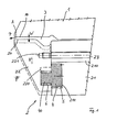
- an extrusion die is shown, which is often also Wide slot extrusion die is called and among other things for Extrusion of flat films, sheets, plates and for Extrusion coating using in an extrusion facility melted thermoplastic is used.
- the extrusion die comprises a first or upper die part 1 and one second or lower nozzle part 2, between which an extrusion gap 3 is formed, by which the one not shown Extrusion device provided melt of thermoplastic directed to an outlet A and from there emerges from the extrusion nozzle according to arrow P.
- the exit opening A is slit-shaped and extends across the entire width of the Extrusion tool.
- the width can be changed W of the same can be changed.
- a Adjustment device provided, which will be explained in more detail below and by means of which the nozzle lips 10 delimiting the outlet opening A, 20 of the first nozzle part 1 or second nozzle part 2 in their distance to each other, which also forms the width W, can be changed.
- Nozzle part 2 formed in several parts and comprises a nozzle back part 21 the front of which is a nozzle front part 22 which supports the nozzle lip 20 arranged.
- a large number of clamping bolts 23 from Nozzle back part 21 forth through a corresponding bore 210 in this a threaded blind hole 221 is screwed into the nozzle front part 22 and produce a to seal the joint between the nozzle back part 21 and Nozzle front part 22 necessary surface pressure.
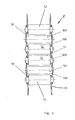
- the rear nozzle part 21 has a receiving groove which is open towards the front part 22 of the nozzle 211 with a rectangular cross-section, into which an adjustment beam 4 is inserted which, like the receiving groove 211, extends in width Extrusion nozzle extends, see also Figure 2.
- the adjustment bar 4 is here with the interposition of an endlessly rotating roller chain 5 stored within the receiving groove 211, so that it according to arrows R in a Direction of displacement, which extends in the width of the Extrusion tool extends, longitudinally displaceable within the Recording groove 211 is guided.
- This longitudinal displacement can for example by a not shown and also in Extension of the extrusion nozzle and on the adjustment beam 4 attacking threaded spindle.
- the adjustment bar 4 on its side facing the nozzle front part 22 several mutually parallel and spaced apart protruding slide cam 40, which over the contour of the Protruding nozzle back 21.
- the slide cams 40 have one Central longitudinal axis S, which is oblique to the longitudinal axis L of the adjusting beam 4th and the receiving groove 211 receiving this runs, for example here at an angle ⁇ of 5 °.
- the protruding slide cams 40 of the adjustment beam 4 are in appropriately trained control grooves 220 performed in Nozzle front part 22 starting from the nozzle back part 21 facing Surface are brought in, as is also the representation according to FIG 2 removable.
- These control grooves 220 are also analogous to the slide cams 40 of the adjustment beam 4 at the same angle ⁇ obliquely to the longitudinal axis L. the adjustment bar 4 and the receiving groove 211 arranged.
- Slide cams 40 are each one with an intermediate layer around the Sliding cam revolving roller chain 6 within the control groove 220 guided.
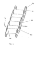
- roller chains 5, 6 explained above are preferably of the same type constructed, but can also be dimensioned differently. in the following is representative of both roller chains 5, 6 of the other Structure of the same using the example of that illustrated in FIGS. 3 to 5 Roller chain 5 explained, the designs are analogous to the Roller chain 6 transferable.
- the roller chain described below is only one possible embodiment with which a roller bearing the components can be realized in the sense of the invention.
- roller chain 5 of a plurality of rollers 52 extending parallel to one another those of the adjustment beam 4 or the slide cam 40 within the Unroll receiving groove 211 or control groove 220.
- Each of these roles 52 has front bearing journals 520, which in the side members 51 and 500 are rotatably mounted.
- the roles are alternately by Side links 51 and 500 of a chain link 50 to the roller chain concatenated, for which purpose the side members 51 and 500 of the support member 50 corresponding, the free ends of the support axles 520 and have holes 510, 502 communicating with one another, see here Figure 4.
- Alternating between successive side members 51 is in each case a support member 50 is provided, which in more detail can also be seen from FIG. 4.
- each of these support members 50th a connecting bridge 501 between two successive Roll 52 the two side links 500 lying on both sides of the roller chain 5 of the support member 50 connects what the roller chain 5 a high Gives stability.
- the connecting bridge 501 is in her Diameter smaller than the rollers 52 so that they do not run with the Adjustment beam 4 and the receiving groove 211 or the sliding cam 40 and the control groove 220 comes into contact, see also FIG. 5.
- roller chain 5 as well as the analog structure Roller chain 6 from a selected according to the requirements wear-resistant material, such as hardened steel is.
- Extrusion die with adjustment lip d. H. with one on a nozzle rear part 21 attached nozzle front part 22, which supports the nozzle lip 20 of course also the use of a roller chain bearing Adjustment bar 4 with protruding slide cams and these receiving Control grooves in an extrusion die with a so-called flex lip, in which the Nozzle lip is flexibly bendable attached to the nozzle part, possible.
Landscapes
- Engineering & Computer Science (AREA)
- Mechanical Engineering (AREA)
- Manufacturing & Machinery (AREA)
- Extrusion Moulding Of Plastics Or The Like (AREA)
- Coating Apparatus (AREA)
- Formation And Processing Of Food Products (AREA)
- Devices For Post-Treatments, Processing, Supply, Discharge, And Other Processes (AREA)
- Manufacturing And Processing Devices For Dough (AREA)
Applications Claiming Priority (4)
| Application Number | Priority Date | Filing Date | Title |
|---|---|---|---|
| DE10129627A DE10129627C1 (de) | 2001-06-20 | 2001-06-20 | Extrusionsdüse |
| DE10129627 | 2001-06-20 | ||
| DE20113293U | 2001-08-10 | ||
| DE20113293U DE20113293U1 (de) | 2001-06-20 | 2001-08-10 | Extrusionsdüse |
Publications (3)
| Publication Number | Publication Date |
|---|---|
| EP1270175A2 true EP1270175A2 (fr) | 2003-01-02 |
| EP1270175A3 EP1270175A3 (fr) | 2004-04-14 |
| EP1270175B1 EP1270175B1 (fr) | 2006-07-26 |
Family
ID=26009552
Family Applications (1)
| Application Number | Title | Priority Date | Filing Date |
|---|---|---|---|
| EP02012158A Expired - Lifetime EP1270175B1 (fr) | 2001-06-20 | 2002-06-01 | Filière d'extrusion |
Country Status (4)
| Country | Link |
|---|---|
| EP (1) | EP1270175B1 (fr) |
| AT (1) | ATE333978T1 (fr) |
| DE (1) | DE50207604D1 (fr) |
| ES (1) | ES2269557T3 (fr) |
Cited By (1)
| Publication number | Priority date | Publication date | Assignee | Title |
|---|---|---|---|---|
| WO2009144073A3 (fr) * | 2008-04-18 | 2010-03-11 | Dürr Ecoclean GmbH | Dispositif de nettoyage et procédé de nettoyage d'une pièce |
Family Cites Families (3)
| Publication number | Priority date | Publication date | Assignee | Title |
|---|---|---|---|---|
| US3267519A (en) * | 1964-10-23 | 1966-08-23 | Du Pont | Differential lock nut adjuster |
| US5679383B1 (en) * | 1994-02-04 | 1999-01-05 | Extrusion Dies Inc | Dual flexible lip extrusion apparatus |
| DE20004784U1 (de) * | 2000-03-15 | 2000-06-15 | "Emo" Extrusion Molding Ges. M.B.H., Micheldorf | Breitschlitzdüse |
-
2002
- 2002-06-01 EP EP02012158A patent/EP1270175B1/fr not_active Expired - Lifetime
- 2002-06-01 ES ES02012158T patent/ES2269557T3/es not_active Expired - Lifetime
- 2002-06-01 AT AT02012158T patent/ATE333978T1/de active
- 2002-06-01 DE DE50207604T patent/DE50207604D1/de not_active Expired - Lifetime
Cited By (2)
| Publication number | Priority date | Publication date | Assignee | Title |
|---|---|---|---|---|
| WO2009144073A3 (fr) * | 2008-04-18 | 2010-03-11 | Dürr Ecoclean GmbH | Dispositif de nettoyage et procédé de nettoyage d'une pièce |
| US8006710B2 (en) | 2008-04-18 | 2011-08-30 | Dürr Ecoclean GmbH | Cleaning device and method for cleaning a workpiece |
Also Published As
| Publication number | Publication date |
|---|---|
| ATE333978T1 (de) | 2006-08-15 |
| DE50207604D1 (de) | 2006-09-07 |
| EP1270175A3 (fr) | 2004-04-14 |
| EP1270175B1 (fr) | 2006-07-26 |
| ES2269557T3 (es) | 2007-04-01 |
Similar Documents
| Publication | Publication Date | Title |
|---|---|---|
| DE3913991A1 (de) | Kontinuierlich arbeitende presse | |
| DE3709555A1 (de) | Abkantpresse | |
| DE2937972A1 (de) | Vorrichtung zum aufbringen einer flaechenpressung auf fortschreitende werkstuecke | |
| EP0958122B1 (fr) | Chenille individuelle destinee a des dispositifs d'evacuation, et dispositifs d'evacuation pour elements allonges | |
| DE3533670A1 (de) | Gerades gleitrollenlager | |
| DE69722050T2 (de) | Bogensegment für Kettenförderer, und ein Ober- und Unterteil für ein solches Bogensegment | |
| EP0254028A2 (fr) | Dispositif d'étirage pour étirer continuellement un boudin de matériau en barres ou tubulaire | |
| DE10129627C1 (de) | Extrusionsdüse | |
| DE3619648C2 (fr) | ||
| DE102010004771B3 (de) | Türband für Aluminiumtüren | |
| EP1297869A1 (fr) | Planche de glisse ,speciallement un ski et écarteur pour une planche de glisse | |
| DE1774925A1 (de) | Fuehrungseinrichtung mit einem laengs einer Fuehrungsstange bewegbaren Schieber | |
| DE10045681A1 (de) | Kontinuierlich arbeitende Presse | |
| DE3326763A1 (de) | Tuerband | |
| DE2723578C2 (fr) | ||
| DE3232147C2 (de) | Schrumpfausgleichseinrichtung für eine Stranggießkokille | |
| EP0028215B1 (fr) | Installation pour mesurer la distance de deux transporteurs à rouleaux qui sont face à face dans une installation à coulée continue | |
| EP1270175B1 (fr) | Filière d'extrusion | |
| DE2831142C2 (de) | Durchbiegungseinstellwalze | |
| DE60211080T2 (de) | Verstellbare Formmatrize, insbesondere für Abkantpressen | |
| DE3227218A1 (de) | Mehrlagenstoffauflauf | |
| EP1069344A1 (fr) | Chaínes à maillons en plaques à articulations à faible usure | |
| DE3400608C2 (de) | Walzgerüst mit einer zwischen Arbeitswalze und Stützwalze eingefügten versetzten Zwischenwalze | |
| DE2824301A1 (de) | Verbindungseinheit fuer rolladenaufbauelemente | |
| DE69817873T2 (de) | Positionierungsapparat |
Legal Events
| Date | Code | Title | Description |
|---|---|---|---|
| PUAI | Public reference made under article 153(3) epc to a published international application that has entered the european phase |
Free format text: ORIGINAL CODE: 0009012 |
|
| AK | Designated contracting states |
Kind code of ref document: A2 Designated state(s): AT BE CH CY DE DK ES FI FR GB GR IE IT LI LU MC NL PT SE TR |
|
| AX | Request for extension of the european patent |
Free format text: AL;LT;LV;MK;RO;SI |
|
| PUAL | Search report despatched |
Free format text: ORIGINAL CODE: 0009013 |
|
| AK | Designated contracting states |
Kind code of ref document: A3 Designated state(s): AT BE CH CY DE DK ES FI FR GB GR IE IT LI LU MC NL PT SE TR |
|
| AX | Request for extension of the european patent |
Extension state: AL LT LV MK RO SI |
|
| 17P | Request for examination filed |
Effective date: 20040521 |
|
| AKX | Designation fees paid |
Designated state(s): AT BE CH CY DE DK ES FI FR GB GR IE IT LI LU MC NL PT SE TR |
|
| 17Q | First examination report despatched |
Effective date: 20050413 |
|
| GRAP | Despatch of communication of intention to grant a patent |
Free format text: ORIGINAL CODE: EPIDOSNIGR1 |
|
| GRAS | Grant fee paid |
Free format text: ORIGINAL CODE: EPIDOSNIGR3 |
|
| GRAA | (expected) grant |
Free format text: ORIGINAL CODE: 0009210 |
|
| AK | Designated contracting states |
Kind code of ref document: B1 Designated state(s): AT BE CH CY DE DK ES FI FR GB GR IE IT LI LU MC NL PT SE TR |
|
| PG25 | Lapsed in a contracting state [announced via postgrant information from national office to epo] |
Ref country code: IT Free format text: LAPSE BECAUSE OF FAILURE TO SUBMIT A TRANSLATION OF THE DESCRIPTION OR TO PAY THE FEE WITHIN THE PRESCRIBED TIME-LIMIT;WARNING: LAPSES OF ITALIAN PATENTS WITH EFFECTIVE DATE BEFORE 2007 MAY HAVE OCCURRED AT ANY TIME BEFORE 2007. THE CORRECT EFFECTIVE DATE MAY BE DIFFERENT FROM THE ONE RECORDED. Effective date: 20060726 Ref country code: NL Free format text: LAPSE BECAUSE OF FAILURE TO SUBMIT A TRANSLATION OF THE DESCRIPTION OR TO PAY THE FEE WITHIN THE PRESCRIBED TIME-LIMIT Effective date: 20060726 Ref country code: FI Free format text: LAPSE BECAUSE OF FAILURE TO SUBMIT A TRANSLATION OF THE DESCRIPTION OR TO PAY THE FEE WITHIN THE PRESCRIBED TIME-LIMIT Effective date: 20060726 Ref country code: GB Free format text: LAPSE BECAUSE OF FAILURE TO SUBMIT A TRANSLATION OF THE DESCRIPTION OR TO PAY THE FEE WITHIN THE PRESCRIBED TIME-LIMIT Effective date: 20060726 Ref country code: IE Free format text: LAPSE BECAUSE OF FAILURE TO SUBMIT A TRANSLATION OF THE DESCRIPTION OR TO PAY THE FEE WITHIN THE PRESCRIBED TIME-LIMIT Effective date: 20060726 |
|
| REG | Reference to a national code |
Ref country code: GB Ref legal event code: FG4D Free format text: NOT ENGLISH |
|
| REG | Reference to a national code |
Ref country code: CH Ref legal event code: EP |
|
| REG | Reference to a national code |
Ref country code: IE Ref legal event code: FG4D Free format text: LANGUAGE OF EP DOCUMENT: GERMAN |
|
| REF | Corresponds to: |
Ref document number: 50207604 Country of ref document: DE Date of ref document: 20060907 Kind code of ref document: P |
|
| PG25 | Lapsed in a contracting state [announced via postgrant information from national office to epo] |
Ref country code: DK Free format text: LAPSE BECAUSE OF FAILURE TO SUBMIT A TRANSLATION OF THE DESCRIPTION OR TO PAY THE FEE WITHIN THE PRESCRIBED TIME-LIMIT Effective date: 20061026 Ref country code: SE Free format text: LAPSE BECAUSE OF FAILURE TO SUBMIT A TRANSLATION OF THE DESCRIPTION OR TO PAY THE FEE WITHIN THE PRESCRIBED TIME-LIMIT Effective date: 20061026 |
|
| PG25 | Lapsed in a contracting state [announced via postgrant information from national office to epo] |
Ref country code: PT Free format text: LAPSE BECAUSE OF FAILURE TO SUBMIT A TRANSLATION OF THE DESCRIPTION OR TO PAY THE FEE WITHIN THE PRESCRIBED TIME-LIMIT Effective date: 20061226 |
|
| NLV1 | Nl: lapsed or annulled due to failure to fulfill the requirements of art. 29p and 29m of the patents act | ||
| GBV | Gb: ep patent (uk) treated as always having been void in accordance with gb section 77(7)/1977 [no translation filed] |
Effective date: 20060726 |
|
| REG | Reference to a national code |
Ref country code: IE Ref legal event code: FD4D |
|
| REG | Reference to a national code |
Ref country code: ES Ref legal event code: FG2A Ref document number: 2269557 Country of ref document: ES Kind code of ref document: T3 |
|
| EN | Fr: translation not filed | ||
| PLBE | No opposition filed within time limit |
Free format text: ORIGINAL CODE: 0009261 |
|
| STAA | Information on the status of an ep patent application or granted ep patent |
Free format text: STATUS: NO OPPOSITION FILED WITHIN TIME LIMIT |
|
| 26N | No opposition filed |
Effective date: 20070427 |
|
| PG25 | Lapsed in a contracting state [announced via postgrant information from national office to epo] |
Ref country code: MC Free format text: LAPSE BECAUSE OF NON-PAYMENT OF DUE FEES Effective date: 20070630 |
|
| REG | Reference to a national code |
Ref country code: CH Ref legal event code: PL |
|
| PG25 | Lapsed in a contracting state [announced via postgrant information from national office to epo] |
Ref country code: LI Free format text: LAPSE BECAUSE OF NON-PAYMENT OF DUE FEES Effective date: 20070630 Ref country code: GR Free format text: LAPSE BECAUSE OF FAILURE TO SUBMIT A TRANSLATION OF THE DESCRIPTION OR TO PAY THE FEE WITHIN THE PRESCRIBED TIME-LIMIT Effective date: 20061027 Ref country code: CH Free format text: LAPSE BECAUSE OF NON-PAYMENT OF DUE FEES Effective date: 20070630 Ref country code: FR Free format text: LAPSE BECAUSE OF FAILURE TO SUBMIT A TRANSLATION OF THE DESCRIPTION OR TO PAY THE FEE WITHIN THE PRESCRIBED TIME-LIMIT Effective date: 20070511 |
|
| PG25 | Lapsed in a contracting state [announced via postgrant information from national office to epo] |
Ref country code: FR Free format text: LAPSE BECAUSE OF FAILURE TO SUBMIT A TRANSLATION OF THE DESCRIPTION OR TO PAY THE FEE WITHIN THE PRESCRIBED TIME-LIMIT Effective date: 20060726 |
|
| PG25 | Lapsed in a contracting state [announced via postgrant information from national office to epo] |
Ref country code: LU Free format text: LAPSE BECAUSE OF NON-PAYMENT OF DUE FEES Effective date: 20070601 Ref country code: CY Free format text: LAPSE BECAUSE OF FAILURE TO SUBMIT A TRANSLATION OF THE DESCRIPTION OR TO PAY THE FEE WITHIN THE PRESCRIBED TIME-LIMIT Effective date: 20060726 |
|
| PGFP | Annual fee paid to national office [announced via postgrant information from national office to epo] |
Ref country code: TR Payment date: 20100601 Year of fee payment: 9 |
|
| PGFP | Annual fee paid to national office [announced via postgrant information from national office to epo] |
Ref country code: ES Payment date: 20110614 Year of fee payment: 10 |
|
| PGFP | Annual fee paid to national office [announced via postgrant information from national office to epo] |
Ref country code: BE Payment date: 20130626 Year of fee payment: 12 |
|
| REG | Reference to a national code |
Ref country code: ES Ref legal event code: FD2A Effective date: 20131030 |
|
| PG25 | Lapsed in a contracting state [announced via postgrant information from national office to epo] |
Ref country code: TR Free format text: LAPSE BECAUSE OF NON-PAYMENT OF DUE FEES Effective date: 20110601 Ref country code: ES Free format text: LAPSE BECAUSE OF NON-PAYMENT OF DUE FEES Effective date: 20120602 |
|
| PG25 | Lapsed in a contracting state [announced via postgrant information from national office to epo] |
Ref country code: BE Free format text: LAPSE BECAUSE OF NON-PAYMENT OF DUE FEES Effective date: 20140630 |
|
| PGFP | Annual fee paid to national office [announced via postgrant information from national office to epo] |
Ref country code: AT Payment date: 20170627 Year of fee payment: 16 |
|
| PGFP | Annual fee paid to national office [announced via postgrant information from national office to epo] |
Ref country code: DE Payment date: 20170627 Year of fee payment: 16 Ref country code: IT Payment date: 20170630 Year of fee payment: 16 |
|
| REG | Reference to a national code |
Ref country code: DE Ref legal event code: R079 Ref document number: 50207604 Country of ref document: DE Free format text: PREVIOUS MAIN CLASS: B29C0047160000 Ipc: B29C0048310000 |
|
| REG | Reference to a national code |
Ref country code: DE Ref legal event code: R119 Ref document number: 50207604 Country of ref document: DE |
|
| REG | Reference to a national code |
Ref country code: AT Ref legal event code: MM01 Ref document number: 333978 Country of ref document: AT Kind code of ref document: T Effective date: 20180601 |
|
| PG25 | Lapsed in a contracting state [announced via postgrant information from national office to epo] |
Ref country code: AT Free format text: LAPSE BECAUSE OF NON-PAYMENT OF DUE FEES Effective date: 20180601 Ref country code: IT Free format text: LAPSE BECAUSE OF NON-PAYMENT OF DUE FEES Effective date: 20180601 Ref country code: DE Free format text: LAPSE BECAUSE OF NON-PAYMENT OF DUE FEES Effective date: 20190101 |