EP1270187A2 - Formverfahren für eine Gelenkprothese und Form zur Durchführung desselben - Google Patents
Formverfahren für eine Gelenkprothese und Form zur Durchführung desselben Download PDFInfo
- Publication number
- EP1270187A2 EP1270187A2 EP02254370A EP02254370A EP1270187A2 EP 1270187 A2 EP1270187 A2 EP 1270187A2 EP 02254370 A EP02254370 A EP 02254370A EP 02254370 A EP02254370 A EP 02254370A EP 1270187 A2 EP1270187 A2 EP 1270187A2
- Authority
- EP
- European Patent Office
- Prior art keywords
- support
- component
- providing
- moulding die
- mould
- Prior art date
- Legal status (The legal status is an assumption and is not a legal conclusion. Google has not performed a legal analysis and makes no representation as to the accuracy of the status listed.)
- Granted
Links
- 238000000465 moulding Methods 0.000 title claims abstract description 67
- 238000000034 method Methods 0.000 title claims abstract description 50
- 230000003014 reinforcing effect Effects 0.000 claims abstract description 49
- 239000000463 material Substances 0.000 claims abstract description 42
- 238000004519 manufacturing process Methods 0.000 claims abstract description 17
- 238000011882 arthroplasty Methods 0.000 claims abstract description 11
- 238000010438 heat treatment Methods 0.000 claims abstract description 4
- 229910052751 metal Inorganic materials 0.000 claims description 7
- 239000002184 metal Substances 0.000 claims description 7
- 229920000642 polymer Polymers 0.000 claims description 7
- 239000004699 Ultra-high molecular weight polyethylene Substances 0.000 claims description 4
- 229920000785 ultra high molecular weight polyethylene Polymers 0.000 claims description 4
- 210000003127 knee Anatomy 0.000 description 35
- 230000007246 mechanism Effects 0.000 description 12
- 229920003023 plastic Polymers 0.000 description 12
- 239000004033 plastic Substances 0.000 description 12
- 210000003041 ligament Anatomy 0.000 description 8
- 239000000843 powder Substances 0.000 description 7
- 239000007943 implant Substances 0.000 description 5
- 210000000629 knee joint Anatomy 0.000 description 5
- -1 polyethylene Polymers 0.000 description 4
- 230000001954 sterilising effect Effects 0.000 description 4
- 238000004659 sterilization and disinfection Methods 0.000 description 4
- 239000004698 Polyethylene Substances 0.000 description 3
- 229910045601 alloy Inorganic materials 0.000 description 3
- 239000000956 alloy Substances 0.000 description 3
- 210000000988 bone and bone Anatomy 0.000 description 3
- 238000013150 knee replacement Methods 0.000 description 3
- 229920000573 polyethylene Polymers 0.000 description 3
- 210000002967 posterior cruciate ligament Anatomy 0.000 description 3
- 230000002787 reinforcement Effects 0.000 description 3
- 210000004872 soft tissue Anatomy 0.000 description 3
- 230000000087 stabilizing effect Effects 0.000 description 3
- 229910001220 stainless steel Inorganic materials 0.000 description 3
- 239000010935 stainless steel Substances 0.000 description 3
- 238000001356 surgical procedure Methods 0.000 description 3
- 210000002303 tibia Anatomy 0.000 description 3
- 238000011883 total knee arthroplasty Methods 0.000 description 3
- RTAQQCXQSZGOHL-UHFFFAOYSA-N Titanium Chemical compound [Ti] RTAQQCXQSZGOHL-UHFFFAOYSA-N 0.000 description 2
- 238000000748 compression moulding Methods 0.000 description 2
- 230000001010 compromised effect Effects 0.000 description 2
- 238000010276 construction Methods 0.000 description 2
- 238000005553 drilling Methods 0.000 description 2
- 230000003647 oxidation Effects 0.000 description 2
- 238000007254 oxidation reaction Methods 0.000 description 2
- 125000006850 spacer group Chemical group 0.000 description 2
- 238000006467 substitution reaction Methods 0.000 description 2
- 239000010936 titanium Substances 0.000 description 2
- 229910052719 titanium Inorganic materials 0.000 description 2
- 210000000689 upper leg Anatomy 0.000 description 2
- 229910000684 Cobalt-chrome Inorganic materials 0.000 description 1
- UFHFLCQGNIYNRP-UHFFFAOYSA-N Hydrogen Chemical compound [H][H] UFHFLCQGNIYNRP-UHFFFAOYSA-N 0.000 description 1
- 206010023204 Joint dislocation Diseases 0.000 description 1
- 229910001069 Ti alloy Inorganic materials 0.000 description 1
- 229920010741 Ultra High Molecular Weight Polyethylene (UHMWPE) Polymers 0.000 description 1
- MTHLBYMFGWSRME-UHFFFAOYSA-N [Cr].[Co].[Mo] Chemical compound [Cr].[Co].[Mo] MTHLBYMFGWSRME-UHFFFAOYSA-N 0.000 description 1
- 210000003484 anatomy Anatomy 0.000 description 1
- QVGXLLKOCUKJST-UHFFFAOYSA-N atomic oxygen Chemical compound [O] QVGXLLKOCUKJST-UHFFFAOYSA-N 0.000 description 1
- 230000004888 barrier function Effects 0.000 description 1
- 238000005452 bending Methods 0.000 description 1
- 230000015556 catabolic process Effects 0.000 description 1
- 239000000919 ceramic Substances 0.000 description 1
- 238000004140 cleaning Methods 0.000 description 1
- 239000010952 cobalt-chrome Substances 0.000 description 1
- 210000004439 collateral ligament Anatomy 0.000 description 1
- 230000000295 complement effect Effects 0.000 description 1
- 238000001816 cooling Methods 0.000 description 1
- 238000006731 degradation reaction Methods 0.000 description 1
- 238000007907 direct compression Methods 0.000 description 1
- 230000000694 effects Effects 0.000 description 1
- 239000011888 foil Substances 0.000 description 1
- 239000011261 inert gas Substances 0.000 description 1
- 238000003754 machining Methods 0.000 description 1
- 229910001092 metal group alloy Inorganic materials 0.000 description 1
- 239000001301 oxygen Substances 0.000 description 1
- 229910052760 oxygen Inorganic materials 0.000 description 1
- 210000004417 patella Anatomy 0.000 description 1
- 230000000452 restraining effect Effects 0.000 description 1
- 239000007787 solid Substances 0.000 description 1
- 239000011343 solid material Substances 0.000 description 1
- 230000006641 stabilisation Effects 0.000 description 1
- 238000011105 stabilization Methods 0.000 description 1
- 210000002435 tendon Anatomy 0.000 description 1
- 239000000602 vitallium Substances 0.000 description 1
Images







Classifications
-
- B—PERFORMING OPERATIONS; TRANSPORTING
- B29—WORKING OF PLASTICS; WORKING OF SUBSTANCES IN A PLASTIC STATE IN GENERAL
- B29C—SHAPING OR JOINING OF PLASTICS; SHAPING OF MATERIAL IN A PLASTIC STATE, NOT OTHERWISE PROVIDED FOR; AFTER-TREATMENT OF THE SHAPED PRODUCTS, e.g. REPAIRING
- B29C70/00—Shaping composites, i.e. plastics material comprising reinforcements, fillers or preformed parts, e.g. inserts
- B29C70/68—Shaping composites, i.e. plastics material comprising reinforcements, fillers or preformed parts, e.g. inserts by incorporating or moulding on preformed parts, e.g. inserts or layers, e.g. foam blocks
- B29C70/72—Encapsulating inserts having non-encapsulated projections, e.g. extremities or terminal portions of electrical components
-
- B—PERFORMING OPERATIONS; TRANSPORTING
- B29—WORKING OF PLASTICS; WORKING OF SUBSTANCES IN A PLASTIC STATE IN GENERAL
- B29L—INDEXING SCHEME ASSOCIATED WITH SUBCLASS B29C, RELATING TO PARTICULAR ARTICLES
- B29L2031/00—Other particular articles
- B29L2031/753—Medical equipment; Accessories therefor
- B29L2031/7532—Artificial members, protheses
-
- Y—GENERAL TAGGING OF NEW TECHNOLOGICAL DEVELOPMENTS; GENERAL TAGGING OF CROSS-SECTIONAL TECHNOLOGIES SPANNING OVER SEVERAL SECTIONS OF THE IPC; TECHNICAL SUBJECTS COVERED BY FORMER USPC CROSS-REFERENCE ART COLLECTIONS [XRACs] AND DIGESTS
- Y10—TECHNICAL SUBJECTS COVERED BY FORMER USPC
- Y10S—TECHNICAL SUBJECTS COVERED BY FORMER USPC CROSS-REFERENCE ART COLLECTIONS [XRACs] AND DIGESTS
- Y10S623/00—Prosthesis, i.e. artificial body members, parts thereof, or aids and accessories therefor
- Y10S623/901—Method of manufacturing prosthetic device
Definitions
- the present invention relates generally to the field of orthopaedics, and more particularly, to a manufacturing method and moulding die for an implant for use in joint arthroplasty.
- the invention relates to joint prostheses. More particularly, the invention is directed to tibial components of knee joint prostheses that can be configured to be either rotatable or non-rotatable.
- Knee arthroplasty is a well known surgical procedure by which a diseased and/or damaged natural knee joint is replaced with a prosthetic knee joint.
- a typical knee prosthesis includes a femoral component, a patella component, a tibial tray or plateau, and a tibial bearing insert.
- the femoral component generally includes a pair of laterally spaced apart condylar portions, the distal surfaces of which articulate with complementary condylar elements formed in a tibial bearing insert.
- the tibial plateau is mounted within the tibia of a patient.
- the tibial bearing insert which is usually made of ultra high molecular weight polyethylene (UHMWPE)
- UHMWPE ultra high molecular weight polyethylene
- the geometry and structure of the tibial bearing insert varies depending upon the needs and joint condition of a patient. Some tibial bearing inserts are designed to be used with joint prostheses that are implanted during procedures that retain one or both of the cruciate ligaments. Others are implanted after removal of one or both cruciate ligaments, and are thus structured to compensate for the loss of these ligaments. Yet other tibial bearing inserts are used with prostheses that provide enhanced stabilization to the knee joint.
- Recent total knee prostheses have been designed which allow for increased freedom of rotation between the femur and the tibia.
- tibial bearing inserts have been designed which allow for rotation of the insert on the tibial tray or plateau.
- the tibial bearing inserts have a central stem which rotationally engages centrally in the tibial stem of the tibial tray implant thereby providing for the rotational motion.
- the posterior cruciate ligaments are sacrificed and a substitute for the posterior cruciate ligaments is required.
- Orthopaedic implants for total knee arthroplasty have been developed which provide for the substitution of the posterior cruciate ligament.
- examples of such implants include the PFC Sigma RP as disclosed in US-4298992 and the LCSTM Complete total knee prosthesis, both of which are sold by DePuy Orthopaedics, Inc., Warsaw, IN.
- These total knee prostheses are designed with tibial components and femoral components which have in conjunction with their articulating surface, a spine and cam mechanism, which is used as a posterior cruciate substituting feature when the posterior cruciate of the knee is sacrificed.
- Such total knee replacement prostheses which include a spine and cam mechanism, typically contain tibial bearing components manufactured from suitable plastic, usually UHMWPE.
- suitable plastic usually UHMWPE.
- One such construction use for a class of total knee replacement prosthesis which is known as constrained prosthesis often incorporate metal reinforcement rods in the construction of the plastic bearing component.
- the bearing insert is constructed so that the metal rod lies within the bearing and thus provides additional support for the central spine element of the bearing.
- Such components are typically manufactured by machining or moulding the bearing component, drilling a central hole, and press fitting the reinforcing metal rod. An example of such a component is described in US-5007933.
- the spine and cam mechanism on the tibial bearing insert may be placed in a suitable position, preferably anterior to the centre line of the insert in the anterior/posterior direction.
- Designs of tibial inserts are available to help reconstruct knees where the stabilizing soft tissue compromises have been made or occurred due to various reasons. In such cases, the tibial bearing inserts are required to experience greater loads in the anterior/posterior and the medial/lateral directions.
- the constrained inserts may be reinforced with a metal rod as mentioned earlier to help distribute the loads experienced by the spine of the polyethylene tibial bearing.
- Total knee joint prostheses have been designed with the spine and cam mechanisms on the tibial bearing insert placed in a position that the central axis of the distal stem portion of the insert that engages the tibial tray and the axis of the superior spine portion that engages the cam of the femoral component are not necessarily collinear.
- first rod could be inserted inside the spine and a second rod could be inserted in the stem of the tibial tray portion of the bearing insert.
- the load on the first rod would be transferred through the polymer portion of the insert to the second rod.
- the polymer strength would then limit the load carrying capacity of this configuration. Such a configuration may not provide the required strength to sufficiently support and reinforce the spine.
- a manufacturing method to produce a tibial bearing insert that may rotate about the tibial tray is thus required which has the strength required for the greater loads in the anterior/posterior and medial/lateral direction of the spine.
- the present invention is directed to providing a tibial bearing insert manufacturing method and tools to perform the same with sufficient strength at the spine to withstand the loads of the mobile knee prosthesis in the anterior/posterior and medial/lateral direction.
- the present invention is directed to tools and methods for making an improved joint prosthesis for total knee replacement that includes a spine and cam mechanism and a distal rotating stem.
- the cam mechanism being on the femoral component and the spine and distal stem being on the bearing component.
- the mechanism is capable of withstanding the greater loads experienced in the anterior/posterior and medial/lateral direction caused by the substitution of the cam and spine for the cruciate ligaments, which may be sacrificed during total knee arthroplasty.
- the spine on the tibial bearing insert made from a method and utilizing a mould according to the present invention is placed anterior to the centerline of the insert in the anterior posterior direction. Therefore, the distal stem portion of the insert that engages the tibial tray and the superior spine portion which engages the cam of the femoral component are not in the same plane.
- the tibial bearing insert manufacturing method of the present invention thus includes providing a reinforcing rod placed internal to the tibial bearing insert which includes an offset feature to accommodate such plane differences.
- the rotating bearing of a knee prosthesis manufacturing method of the present invention thus includes the step of providing polymeric material with reinforcing a first component including a first portion on a first centre line and a second portion on a second centre line such that the first portion within the polymeric material distal stem may engage the tibial tray and the second portion within the polymeric material spine may be cooperating with the cam mechanism in the femoral component of the knee prosthesis.
- a method of manufacturing a polymeric bearing component for use in joint arthroplasty includes the step of providing a non-linear reinforcing support of a durable material having a first end and a second end.
- the method further includes the step providing a moulding die adapted for manufacturing the bearing component for use in total joint arthroplasty and having a first mould portion and a second mould portion.
- the first mould portion is adapted to provide a first surface of the bearing component for cooperation with the first joint component and the second mould portion is adapted to provide a second surface of the bearing component for cooperation with the second joint component.
- the method further includes the steps of positioning the support in a desired position within the moulding die with one of the first end and the second end located in the first mould portion, adding mouldable polymeric material into the moulding die, substantially surrounding the support with the mouldable material, heating and pressurizing the mould, permitting the mouldable material to cool to form the bearing component, and removing the component from the moulding die.
- a moulding die for use to mould a mouldable material over a substantial portion of a reinforcing support having first and second ends.
- the moulding die provides an article for use in joint arthroplasty.
- the moulding die includes a first mould portion having a first forming surface and a second mould portion having a second forming surface and being mateable with the first mould portion.
- the first die portion and the second mould portion form a cavity there between when the first mould portion and the second mould portion are mated, the first forming surface and the second forming surface define at least a portion of the outer periphery of the article.
- the moulding die also includes a positioner for spacing the reinforcing support within the cavity with at least a portion of the support spaced from at least one of the first forming surface and the second forming surface.
- the positioner is adapted to position the first end of the reinforcing support adjacent the first forming surface and adapted to position the second end of the reinforcing support adjacent the second forming surface.
- the positioner is adapted for spacing the support from at least a portion of the first forming surface and the second forming surface.
- the positioner is adapted to space the support from the first forming surface and the second forming surface a distance of at least 5 mm.
- the positioner is adapted to space at least 95% of the surface area of the support from the first forming surface and the second forming surface.
- the positioner comprises a spacer.
- the spacer comprises a pin.
- the positioner comprises at least one of a metal and a polymer.
- the die includes a retractor for retracting said positioner from the cavity.
- the die includes an orientation feature cooperable with the moulding die for adjusting the orientation of the support within said die; preferably the orientation feature is integral with said positioner.
- the positioner comprises a first pin and a second pin; and the first pin comprises a flat surface formed thereon, said flat surface being cooperable with the support to orient said support with respect to said moulding die.
- the technical advantages of the present invention include the ability to allow for the desired kinematics of the knee during a full range of motion for patients in which the cruciate ligaments have either been severely damaged or have been removed or sacrificed. In such conditions the femoral and tibial components of the knee prosthesis need to be constrained with respect to each other by use of, for example, a spine and cam mechanism.
- the reinforcing support member may be placed within a moulding die and a tibial bearing insert may be moulded incorporating the a non-linear support member.
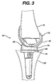
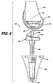
- FIG 8 shows a joint prosthesis in the form of knee prosthesis 10 for use in the mould and with the process of the present invention as shown.
- the knee prosthesis 10 includes a femoral component or first joint component 12 for attachment to femur or first long bone 14.
- the prosthesis 10 further includes a tibial tray or second joint component 16 for attachment to tibia or second long bone 20.
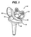
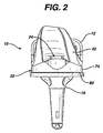
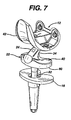
- the femoral component 12 and the tibial component 16 are shown in greater detail in Figures 1-9 and 16-19.
- the femoral component 12 and the tibial component 16 are made of any suitable durable material, which is biocompatible with the human body.
- the femoral component 12 and the tibial component 16 may, for example, be made of a metal alloy, for example, cobalt- chromium-molybdenum, a titanium alloy, or be made of stainless steel.
- the knee prosthesis 10 further includes a bearing component 22.
- the bearing component 22 is positionable between the femoral component 12 and the tibial tray 16.
- the bearing component 22 cooperates with the femoral component 12 and the tibial tray 16 to provide for the desired kinematics of the knee prosthesis.
- the prosthesis as shown in Figures 1-9 and 16-19 are commonly referred to as a mobile bearing prosthesis or a mobile bearing knee.
- Such mobile bearing knees have been provided by DePuy Orthopaedics, Inc. under the trade name LCS since about 1977.
- Mobile bearing knees of this type are different than fixed bearing knees in that the tibial tray 16 and the bearing component 22 may be physically separated from each other.
- the use of mobile bearing knees may require that the patient have satisfactory cruciate ligaments and tendons necessary to maintain the proper relationship of the femoral component to the bearing component.
- one solution to restraining the femoral component 12 with respect to the tibial tray 16 is by the use of a mechanism in the form of a spine 24 located on the bearing component 22 which mates with cam 26 located on femoral component 12.
- the femoral component 12 includes femoral face 30 which cooperate with spine faces 32 on the spine 24.
- the spine faces 32 define a spine width SW which is related to the femoral width CW defined by femoral faces 30 to allow for the desired kinematics in the medial- lateral direction.
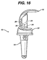
- the spine 24 includes a cam cooperating face or first surface 34 with which the spine cooperating face 35 of the cam 26 cooperates (see Figure 16). It should be appreciated that for patients in which the posterior cruciate is severely damaged, compromised or missing, or when the stabilizing soft tissue has been compromised, the forces on the spine 24 both anterior/posterior and medial/lateral can be quite severe.
- the bearing component 22 is made of a polymeric material, for example, polyethylene.
- the bearing component 22 is made of UHMWPE.
- the bearing component 22 may be further processed to improve the wear properties of contact surface 40 of the bearing component.
- the contact surface 40 is that surface that is in contact with outer periphery 42 of the femoral component 12.
- Methods of improving the wear properties of UHMWPE include a process known as Gamma Vacuum Foil (GVF), as disclosed in US-5577368, and a process known as the MarathonTM process, as disclosed in US-6017975, US-6242507 and US-6,228,900.
- GVF Gamma Vacuum Foil
- the bearing component 22 of the prosthesis 10 includes a first component or reinforcing component 36.
- the first component 36 serves to strengthen or support the bearing component 22 so that the spine 24 may withstand the forces that are present in the spine of the knee prosthesis 10 when the cruciate ligaments and collateral ligaments and stabilizing soft tissue cannot support the knee properly.
- the bearing component 22 is preferably made of a polymer, and since the first component 36 is to strengthen the bearing component 22, the first component 36 is preferably made of a higher strength material than the polymer, preferably a material with a higher modulus of elasticity.
- the first component 36 may be made of a metal that is a material compatible with the human anatomy, such as, stainless steel, a titanium and the alloys or a cobalt-chromium-molybdenum alloy.
- an optimum design of the components that comprise a knee prosthesis may include an tibial tray 16 having a central pivot axis 44 which is not coincident with centre line 46 of the spine 24 of the bearing component 22.
- the bearing component 22 of the prosthesis 10 includes the first component 36 which is designed to accommodate the fact that centerline 44 of the central pivot stem of the tibial tray 16 is offset from centerline 46 of the spine 24 (see Figure 8).
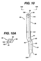
- the first component 36 is designed with a first centerline 50, which is not coincident with second centerline 52.
- the first centerline 50 of the first component 36 is coincident with central pivot stem centerline 44 of tibial tray 16.
- the second centerline 52 of the first component 36 is coincident with the centerline 46 of the spine 24.
- the first component 36 includes a first portion 54, which defines the first centerline 50 thereof.
- the first component 36 further includes a second portion 56 thereof, which defines the second centerline 52 thereof.
- the first centerline 50 and the second centerline 52 are non-coincidental.
- the first centerline 50 may be parallel and spaced from the second centerline 52. It should be appreciated, however, that the first centerline 50 and the second centerline 52 may, in fact, be skewed or converging or diverging. As shown, in Figure 10, however, the first centerline 50 and the second centerline 52 are separated and offset a distance CO which is related to the offset SO between the centerline of 46 of spine 24 and the centerline 44 of the tibial tray 16 (see Figure 8).
- the first component 36 includes a connecting portion 60 positioned between first portion 54 and second portion 56.
- the connecting portion 60 may have any suitable shape, but preferably for strength and simplicity, the connecting portion 60 is an arcuate portion. In such a configuration, the shape of the connecting portion 60 is defined by a pair of radii, R1 and R2, which may, for example, be similar.
- the first component 36 may have any suitable shape capable of providing for support with a pair of offset centrelines, it should be appreciated that for simplicity, and as shown in Figure 10A, the first component 36 may have a uniform cross section.
- the cross section of the first component may be square, triangular, hexagonal or as shown in Figure 10A may be circular.
- a circular cross section may provide for optimum bending strength in a variety of directions for a given weight or size of the first component 36.
- the first component 36 may be hollow or as shown in Figure 10 may be made of a generally solid material. Due to space constraints the first component 36 may be solid as shown in Figure 10.
- the bearing component 22 including the first component 36 may be made by a number of methods but cannot simply and easily be made by first making the bearing component 22 and then preparing an opening or conduit for installing the first component 36 therein. Therefore, typical methods of providing a reinforcing rod to a bearing component 22 in the form of drilling a hole in the bearing component 22 and inserting a straight cylindrical rod therein is not possible.
- the bearing component 22 is preferably made by a moulding process, for example, a compression moulding process or any moulding process by which the polymeric material may be processed. It should be appreciated, however, that the first component 36 may be made by other methods. For example, the bearing component 22 may be made by adding the polymeric material to the first component 36 by applying the material onto the first component or other methods of applying the polymeric material.
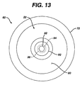
- the bearing component 22 is preferably made in moulding die 62. While the bearing component 22 may be manufactured utilizing any suitable moulding technique, preferably, and as shown in Figure 12, the moulding die 62 is for use with direct compression moulding. Compression moulding consists of consolidating a plastic powder in a mould cavity. Plastic powder is placed into the moulding die 62, the die is closed and pressure is applied to compress, heat, and cause flow of the plastic to be conformed to the cavity shape.
- the moulding die 62 is made in a shape including an inner forming surface 64 which is made in the shape of the final finished bearing component 22.
- the inner forming surface 64 is sized to allow for appropriate shrinking dimensions as is known in the art.
- the moulding die is made in several pieces. Typically, a base or bottom mould or a first mould portion 66 is utilized to form articular surface or first surface 70 and cam cooperating face 34, of the bearing component 22. The cam cooperating face 34 is formed by first forming surface of base mould 66.
- the moulding die 62 also includes a body or side mould 72. The body 72 is utilized to form the curved profile 74 of the bearing component 22. Also, the moulding die 62 further includes a plunger assembly or second mould portion 76. The plunger assembly 76 is utilized to form bottom bearing surface or second surface 80 and the rotating shaft 82. The rotating shaft 82 is formed by second forming surface of plunger assembly 76.
- One mould may be used to obtain varying thicknesses of the bearing component 22.
- the moulding die 62 is modified to support first component 36 in the form of, for example, a reinforcing rod.
- reinforcing rod 36 is position spaced from the inner forming surface 64.
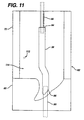
- the reinforcing rod 36 is kept spaced from the inner forming surface 64 by use of an orientation feature 84.
- the orientation feature 84 is utilized to space or position the reinforcing rod 36 within the moulding die 62.
- the positioner or support system 84 may support or secure the first component of 36 at any suitable position on the first component 36.
- the positioner 84 may be located on first end 86 of the reinforcing rod 36.
- the positioner 84 may include a sole positioning member, which interacts with first end 86 of the reinforcing rod 36. If the positioner is located only on one end and the rod is held at that one end, that portion of the die including the positioner either at the base or bottom mould 66 or the plunger or top mould 76 must provide rigid temporary attachment of the reinforcing rod 36 to the positioner 84.
- the present invention may be practised utilizing a sole positioner located on one end of the reinforcing rod 36, such a configuration may have some problems in that the tolerance between the positioner and the reinforcing rod may be such that the accuracy of the position of the reinforcing rod 36 within the moulding die 62 may not be sufficiently accurate resulting in the misposition of the reinforcing rod 36 within the finished first component 36. Misposition may occur either in the anterior-posterior or medial-lateral direction. Additionally, the reinforcing pin 36 may be rotationally mispositioned with respect to the superior spine and distal stem.
- the positioner 84 is in the form of a first positioner 90 located at the first end 86 of the reinforcing rod 36 and a second positioner 92 located at second end 94 of the reinforcing rod 36. If the reinforcing rod 36 is held at both the first end 86 and the second end 94 of the rod 36, then one end, for example, first end 86 must be a sliding temporary attachment and the other end, for example, second end 94 or second positioner 92 must be a rigid temporary attachment.
- a sliding temporary attachment is necessary as the two ends of the moulding die approach and separate from each other during each moulding cycle. Additionally, the sliding temporary attachment provides for rotational alignment to obtain the optional position of the reinforcing rod 36 in the spine by allowing approximately equal polymeric material around the reinforcing rod 36.
- the moulding die may include an orientation feature 100 to optimally angularly orient the reinforcing rod 36 with respect to the inner forming surface 64 and eventually the first component 36.
- the orientation feature 100 may, for example, be included with the positioners 90 and 92 and may, as shown in Figure 12, be in the form of flat 102 located on the second positioner 92. As shown in Figure 12, the orientation feature 100 is in the form of six equally spaced flats, three of which are shown. Therefore, the positioner 84 and the orientation features are in the form of a hexagonal rod. An additional flat may help fine-tuning of the position within the mould.
- the reinforcing rod 36 includes positioning features in the form of, for example, first recess 104, which is located on first end 86 of the rod 36, and second recess 106, which is located on second end 94 of the rod 36.
- the first recess 104 matingly receives the first positioner 90 while the second recess 106 receives the second positioner 92 (see Figure 11).
- the second recess 106 includes a recess flat 110 which mate with flat 102 on second positioner 92.
- plastic powder 112 is added in the proper amount into cavity 114 of the moulding die 62.
- the moulding die 62 is closed by the positioning of the plunger assembly or top mould 76 over the body or side mould 72 of the moulding die 62.
- the bearing component 22 is fully formed by subjecting the moulding die 62 to the well-known conditions of pressure and temperature and time required to consolidate the powder 112. After appropriate cooling, the moulding die 62 is opened by the removal of the plunger assembly or top mould 76 from the body or side mould 72. The bearing component 22, including the reinforcing rod 36, is then removed from the cavity 114 of the moulding die 62. After proper cleaning additional powder 112 and a new reinforcing rod 36 is added to the cavity 114 and the process is repeated in order to obtain a second component.
- First step 120 of the process described in Figure 15, is the step of providing a support of a durable material.
- the durable material may, for example, be in the form of cobalt-chrome alloy, stainless steel or titanium and its alloys.
- the support may be in the form of, for example, an elongated member, for example, a rod.
- the rod, as described in the present invention is in the form of a bent rod or a rod having two substantially linear portions with the portions being skewed or non-linear with respect to each other.
- Second step 122 of the process is the step of providing a moulding die adapted for manufacturing a component for use in total joint arthroplasty.
- Third step 124 in the process is the step of placing the support into the moulding die in the desired portion.
- Fourth step 126 of the process is adding mouldable material into the moulding die.
- Fifth step 130 in the process for making a component is the step of substantially surrounding the support with mouldable powder material.
- Sixth step 131 of the process is the step of heating and pressurizing the mould, and thus the mouldable material powder.
- Seventh step 132 of the process is the step of permitting the mouldable material to cool to form the component and eighth step 134 of the process is the step of removing the component from the moulding die.
- the prosthesis 10 including the bearing component 22 since the prosthesis 10 including the bearing component 22 will be implanted into the human body, it is essential that the prosthesis 10, including the bearing component 22, be sterilized.
- the bearing component 22 may be sterilized by subjecting the bearing component 22 to gamma irradiation.
- the subjection of the bearing component 22 to gamma irradiation may lead to the presence of free radicals within the polymer or polyethylene from which the bearing component 22 is typically manufactured.
- the presence of free radicals within the bearing component 22 may lead to early degradation through an oxidation process of the bearing component 22.
- the bearing component 22 is preferably barrier packaged in vacuum or inert gas to keep the oxygen out and also to trap hydrogen gas generated by the sterilization process inside the package. Such treatment precludes or reduces oxidation of the bearing material and sufficient sterilization for the bearing component 22.
- the bearing component 22 is shown having been moulded in the moulding die 62 (see Figures 12 & 13).
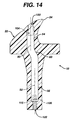
- the bearing component 22 in order that the first positioner 90 and the second positioner 92 may be removed from the cavity 114, and from the bearing component 22 when it is removed from the cavity 114 of the moulding die 62, the bearing component 22 includes a first bearing component opening 120 located in line and above the first recess 104 of the reinforcing rod 36.
- the bearing component 22 further includes a second bearing component opening 122 extending outwardly from the second recess 106 of the reinforcing rod 36.
- the first bearing component 120 and the second bearing component opening 122 provide for access to the reinforcing rod 36 from the outside of the bearing component 22.
- a knee may be provided with improved load carrying capacity in the anterior/posterior and medial/lateral directions for the spine and cam mechanism in situations in which the centre line of the insert, which engages the tibial tray and the superior spine portion, which rotationally engage the cam of the femoral component, are not in the same plane. In such situations where these planes are different, the kinematics of the knee may be improved.
- a tibial tray may be provided with a sufficiently strong spine to support the patient when in a locked knee, standing position.
- the non-linear support rod may be properly positioned within the tibial bearing insert.
- the support rod may be adjusted with respect to the tibial bearing insert during the manufacturing of the tibial bearing insert to optimize the load transfer mechanism through the spine.
Landscapes
- Chemical & Material Sciences (AREA)
- Engineering & Computer Science (AREA)
- Composite Materials (AREA)
- Mechanical Engineering (AREA)
- Prostheses (AREA)
- Moulding By Coating Moulds (AREA)
Applications Claiming Priority (4)
| Application Number | Priority Date | Filing Date | Title |
|---|---|---|---|
| US30209701P | 2001-06-29 | 2001-06-29 | |
| US302097P | 2001-06-29 | ||
| US10/154,732 US6821470B2 (en) | 2001-06-29 | 2002-05-24 | Joint prosthesis molding method |
| US154732 | 2002-05-24 |
Publications (3)
| Publication Number | Publication Date |
|---|---|
| EP1270187A2 true EP1270187A2 (de) | 2003-01-02 |
| EP1270187A3 EP1270187A3 (de) | 2004-02-11 |
| EP1270187B1 EP1270187B1 (de) | 2006-12-13 |
Family
ID=26851722
Family Applications (1)
| Application Number | Title | Priority Date | Filing Date |
|---|---|---|---|
| EP02254370A Expired - Lifetime EP1270187B1 (de) | 2001-06-29 | 2002-06-24 | Formverfahren für eine Gelenkprothese und Form zur Durchführung desselben |
Country Status (8)
| Country | Link |
|---|---|
| US (1) | US6821470B2 (de) |
| EP (1) | EP1270187B1 (de) |
| JP (1) | JP4233824B2 (de) |
| AT (1) | ATE347989T1 (de) |
| AU (1) | AU785208B2 (de) |
| DE (1) | DE60216668T2 (de) |
| DK (1) | DK1270187T3 (de) |
| ES (1) | ES2277613T3 (de) |
Cited By (2)
| Publication number | Priority date | Publication date | Assignee | Title |
|---|---|---|---|---|
| US6821470B2 (en) | 2001-06-29 | 2004-11-23 | Depuy Products, Inc. | Joint prosthesis molding method |
| US6962607B2 (en) | 2001-06-30 | 2005-11-08 | Depuy Products, Inc. | Joint replacement prosthesis component with non linear insert |
Families Citing this family (18)
| Publication number | Priority date | Publication date | Assignee | Title |
|---|---|---|---|---|
| AU2004206826B8 (en) | 2003-01-16 | 2009-03-26 | Cambridge Polymer Group, Inc. | Methods for making oxidation resistant polymeric material |
| US7351367B2 (en) * | 2003-04-11 | 2008-04-01 | Bionix Prosthetic Solutions, Inc. | Adapter bracket for prostheses, method and apparatus for forming prosthetic device with transfer of proper alignment |
| CA2719033C (en) * | 2007-12-07 | 2014-07-08 | Zimmer Orthopaedic Surgical Products, Inc. | Spacer mold and methods therefor |
| US8435241B2 (en) * | 2007-12-20 | 2013-05-07 | Depuy Products, Inc. | Keel punch impactor with connection device |
| CA2742050C (en) | 2008-10-29 | 2014-11-25 | Scott M. Sporer | Spacer molds with releasable securement |
| US8926619B2 (en) | 2011-06-30 | 2015-01-06 | Depuy (Ireland) | Method of surgically preparing a tibia for implantation of a prosthetic component |
| US8852197B2 (en) | 2011-06-30 | 2014-10-07 | Depuy (Ireland) | Surgical instrument assemblies for use in surgically preparing a tibia for implantation of a prosthetic component |
| US8951301B2 (en) | 2011-06-30 | 2015-02-10 | Depuy (Ireland) | Method of using a trialing system for a knee prosthesis |
| US8968412B2 (en) | 2011-06-30 | 2015-03-03 | Depuy (Ireland) | Trialing system for a knee prosthesis and method of use |
| USD666713S1 (en) * | 2011-06-30 | 2012-09-04 | Depuy Products, Inc. | Tibial keel punch |
| US8986390B2 (en) | 2011-06-30 | 2015-03-24 | Depuy (Ireland) | Method of trialing a knee prosthesis |
| US8939986B2 (en) | 2011-06-30 | 2015-01-27 | Depuy (Ireland) | Surgical instruments for use in surgically preparing a tibia for implantation of a prosthetic component |
| US9861491B2 (en) | 2014-04-30 | 2018-01-09 | Depuy Ireland Unlimited Company | Tibial trial system for a knee prosthesis |
| US10195056B2 (en) | 2015-10-19 | 2019-02-05 | Depuy Ireland Unlimited Company | Method for preparing a patient's tibia to receive an implant |
| US10537445B2 (en) | 2015-10-19 | 2020-01-21 | Depuy Ireland Unlimited Company | Surgical instruments for preparing a patient's tibia to receive an implant |
| US10022794B1 (en) | 2017-01-13 | 2018-07-17 | General Electric Company | Additive manufacturing using a mobile build volume |
| US20180200962A1 (en) | 2017-01-13 | 2018-07-19 | General Electric Company | Additive manufacturing using a dynamically grown build envelope |
| US10478893B1 (en) * | 2017-01-13 | 2019-11-19 | General Electric Company | Additive manufacturing using a selective recoater |
Citations (2)
| Publication number | Priority date | Publication date | Assignee | Title |
|---|---|---|---|---|
| US4298992A (en) | 1980-01-21 | 1981-11-10 | New York Society For The Relief Of The Ruptured And Crippled | Posteriorly stabilized total knee joint prosthesis |
| US5007933A (en) | 1989-01-31 | 1991-04-16 | Osteonics Corp. | Modular knee prosthesis system |
Family Cites Families (41)
| Publication number | Priority date | Publication date | Assignee | Title |
|---|---|---|---|---|
| US4501031A (en) * | 1981-01-22 | 1985-02-26 | Zimmer, Inc. | Metal and plastic composite tibial component for knee joint |
| US4997445A (en) * | 1989-12-08 | 1991-03-05 | Zimmer, Inc. | Metal-backed prosthetic implant with enhanced bonding of polyethylene portion to metal base |
| US5139521A (en) * | 1990-01-27 | 1992-08-18 | Ingrid Schelhas | Knee prosthesis |
| US5358527A (en) * | 1991-03-22 | 1994-10-25 | Forte Mark R | Total knee prosthesis with resurfacing and posterior stabilization capability |
| US5330534A (en) * | 1992-02-10 | 1994-07-19 | Biomet, Inc. | Knee joint prosthesis with interchangeable components |
| US5282866A (en) * | 1992-02-12 | 1994-02-01 | Osteonics Corp. | Prosthetic knee tibial component with axially ribbed keel and apparatus for effecting implant |
| US5176684A (en) * | 1992-02-20 | 1993-01-05 | Dow Corning Wright | Modular shaping and trial reduction guide for implantation of posterior-stabilized femoral prosthesis and method of using same |
| US5413604A (en) * | 1992-12-24 | 1995-05-09 | Osteonics Corp. | Prosthetic knee implant for an anterior cruciate ligament deficient total knee replacement |
| US5830396A (en) * | 1993-01-21 | 1998-11-03 | Biomet, Inc. | Method for processing thermoplastics, thermosets and elastomers |
| US5370699A (en) * | 1993-01-21 | 1994-12-06 | Orthomet, Inc. | Modular knee joint prosthesis |
| US5405396A (en) * | 1993-07-01 | 1995-04-11 | Zimmer, Inc. | Tibial prosthesis |
| US5944756A (en) * | 1994-02-22 | 1999-08-31 | Johnson & Johnson Professional, Inc. | Modular prosthesis with offset attachment mechanism |
| US5549686A (en) * | 1994-06-06 | 1996-08-27 | Zimmer, Inc. | Knee prosthesis having a tapered cam |
| DE4434806B4 (de) | 1994-09-29 | 2007-05-24 | Peter Brehm | Kniegelenksprothese |
| GB9420071D0 (en) * | 1994-10-05 | 1994-11-16 | Howmedica | Metal backing for inclusion in the manufacture of a prosthetic component |
| EP0724868B1 (de) | 1995-01-31 | 2001-06-27 | Sulzer Orthopädie AG | Gelenkprothese, insbesondere Kniegelenkprothese |
| US5702460A (en) * | 1995-02-15 | 1997-12-30 | Smith & Nephew, Inc. | Revision femoral trial prosthesis |
| US5609642A (en) * | 1995-02-15 | 1997-03-11 | Smith & Nephew Richards Inc. | Tibial trial prosthesis and bone preparation system |
| US5609643A (en) * | 1995-03-13 | 1997-03-11 | Johnson & Johnson Professional, Inc. | Knee joint prosthesis |
| US5577368A (en) * | 1995-04-03 | 1996-11-26 | Johnson & Johnson Professional, Inc. | Method for improving wear resistance of polymeric bioimplantable components |
| US5871546A (en) * | 1995-09-29 | 1999-02-16 | Johnson & Johnson Professional, Inc. | Femoral component condyle design for knee prosthesis |
| US5658344A (en) * | 1995-12-29 | 1997-08-19 | Johnson & Johnson Professional, Inc. | Tibial insert reinforcement pin |
| US5755808A (en) * | 1996-06-27 | 1998-05-26 | Joint Medical Products, Corporation | Connector plug for multi-component orthopedic implant |
| US6228900B1 (en) * | 1996-07-09 | 2001-05-08 | The Orthopaedic Hospital And University Of Southern California | Crosslinking of polyethylene for low wear using radiation and thermal treatments |
| US6004351A (en) * | 1996-09-14 | 1999-12-21 | Mizuho Ika Kogyo Kabushiki Kaisha | Prosthetic knee joint |
| US6125255A (en) * | 1996-09-23 | 2000-09-26 | Xerox Corporation | Magnet assembly with inserts and method of manufacturing |
| US6017975A (en) * | 1996-10-02 | 2000-01-25 | Saum; Kenneth Ashley | Process for medical implant of cross-linked ultrahigh molecular weight polyethylene having improved balance of wear properties and oxidation resistance |
| DE59707850D1 (de) * | 1997-01-10 | 2002-09-05 | Sulzer Orthopaedie Ag Baar | Tibiaplattform für ein künstliches Kniegelenk |
| FR2760352B3 (fr) | 1997-03-10 | 1999-04-16 | Philippe Berret | Prothese totale du genou |
| US5824103A (en) * | 1997-05-12 | 1998-10-20 | Howmedica Inc. | Tibial prosthesis |
| US6039764A (en) * | 1997-08-18 | 2000-03-21 | Arch Development Corporation | Prosthetic knee with adjusted center of internal/external rotation |
| US6123728A (en) * | 1997-09-17 | 2000-09-26 | Smith & Nephew, Inc. | Mobile bearing knee prosthesis |
| US6123729A (en) * | 1998-03-10 | 2000-09-26 | Bristol-Myers Squibb Company | Four compartment knee |
| US6660039B1 (en) * | 1998-05-20 | 2003-12-09 | Smith & Nephew, Inc. | Mobile bearing knee prosthesis |
| JP4503114B2 (ja) | 1998-06-10 | 2010-07-14 | デピュイ・オルソペディックス・インコーポレイテッド | 架橋成形したプラスチック支持体 |
| US6126692A (en) * | 1998-06-25 | 2000-10-03 | New York Society For The Relief Of The Ruptured And Crippled Maintaining The Hospital For Special Surgery | Retaining mechanism for a modular tibial component of a knee prosthesis |
| US6165223A (en) * | 1999-03-01 | 2000-12-26 | Biomet, Inc. | Floating bearing knee joint prosthesis with a fixed tibial post |
| US6413279B1 (en) * | 1999-03-01 | 2002-07-02 | Biomet, Inc. | Floating bearing knee joint prosthesis with a fixed tibial post |
| US6620198B2 (en) * | 1999-10-07 | 2003-09-16 | Exactech, Inc. | Composite bearing inserts for total knee joints |
| US6475241B2 (en) | 2000-03-13 | 2002-11-05 | Biomedical Engineering Trust I | Posterior stabilized knee replacement with bearing translation for knees with retained collateral ligaments |
| US6821470B2 (en) | 2001-06-29 | 2004-11-23 | Depuy Products, Inc. | Joint prosthesis molding method |
-
2002
- 2002-05-24 US US10/154,732 patent/US6821470B2/en not_active Expired - Lifetime
- 2002-06-24 DE DE60216668T patent/DE60216668T2/de not_active Expired - Lifetime
- 2002-06-24 ES ES02254370T patent/ES2277613T3/es not_active Expired - Lifetime
- 2002-06-24 AT AT02254370T patent/ATE347989T1/de active
- 2002-06-24 EP EP02254370A patent/EP1270187B1/de not_active Expired - Lifetime
- 2002-06-24 DK DK02254370T patent/DK1270187T3/da active
- 2002-06-26 AU AU50642/02A patent/AU785208B2/en not_active Expired
- 2002-07-01 JP JP2002192570A patent/JP4233824B2/ja not_active Expired - Lifetime
Patent Citations (2)
| Publication number | Priority date | Publication date | Assignee | Title |
|---|---|---|---|---|
| US4298992A (en) | 1980-01-21 | 1981-11-10 | New York Society For The Relief Of The Ruptured And Crippled | Posteriorly stabilized total knee joint prosthesis |
| US5007933A (en) | 1989-01-31 | 1991-04-16 | Osteonics Corp. | Modular knee prosthesis system |
Cited By (3)
| Publication number | Priority date | Publication date | Assignee | Title |
|---|---|---|---|---|
| US6821470B2 (en) | 2001-06-29 | 2004-11-23 | Depuy Products, Inc. | Joint prosthesis molding method |
| US6962607B2 (en) | 2001-06-30 | 2005-11-08 | Depuy Products, Inc. | Joint replacement prosthesis component with non linear insert |
| US8083802B2 (en) | 2001-06-30 | 2011-12-27 | Deput Products, Inc. | Prosthetic bearing with encapsulated reinforcement |
Also Published As
| Publication number | Publication date |
|---|---|
| DE60216668T2 (de) | 2007-09-27 |
| AU785208B2 (en) | 2006-11-02 |
| EP1270187B1 (de) | 2006-12-13 |
| EP1270187A3 (de) | 2004-02-11 |
| ES2277613T3 (es) | 2007-07-16 |
| DK1270187T3 (da) | 2007-03-26 |
| US20030006530A1 (en) | 2003-01-09 |
| AU5064202A (en) | 2003-01-02 |
| DE60216668D1 (de) | 2007-01-25 |
| ATE347989T1 (de) | 2007-01-15 |
| JP2003111780A (ja) | 2003-04-15 |
| JP4233824B2 (ja) | 2009-03-04 |
| US6821470B2 (en) | 2004-11-23 |
Similar Documents
| Publication | Publication Date | Title |
|---|---|---|
| EP1269940B1 (de) | Prothese für Gelenkersatz mit ungeradem Einsatz | |
| EP1270187B1 (de) | Formverfahren für eine Gelenkprothese und Form zur Durchführung desselben | |
| CA2542619C (en) | High flexion articular insert | |
| KR102399697B1 (ko) | 무릎 관절용 구속형 스페이서 장치 | |
| EP3400911B1 (de) | Tibiaplateau mit fixiermerkmalen | |
| CN107661161B (zh) | 全膝关节植入物假体组件和方法 | |
| US20170281354A1 (en) | Constrained Prosthesis For The Knee Joint | |
| WO2019145965A1 (en) | Distal femur total knee prosthesis with self limiting small angle tibial-femoral rotation | |
| AU785375B2 (en) | Joint replacement prosthesis component with non linear insert | |
| AU785369B2 (en) | Surface sterilizable joint replacement prosthesis component with insert | |
| Ronca et al. | Knee Joint Replacements | |
| AU2011221425A1 (en) | High flexion articular insert |
Legal Events
| Date | Code | Title | Description |
|---|---|---|---|
| PUAI | Public reference made under article 153(3) epc to a published international application that has entered the european phase |
Free format text: ORIGINAL CODE: 0009012 |
|
| AK | Designated contracting states |
Kind code of ref document: A2 Designated state(s): AT BE CH CY DE DK ES FI FR GB GR IE IT LI LU MC NL PT SE TR |
|
| AX | Request for extension of the european patent |
Free format text: AL;LT;LV;MK;RO;SI |
|
| PUAL | Search report despatched |
Free format text: ORIGINAL CODE: 0009013 |
|
| AK | Designated contracting states |
Kind code of ref document: A3 Designated state(s): AT BE CH CY DE DK ES FI FR GB GR IE IT LI LU MC NL PT SE TR |
|
| AX | Request for extension of the european patent |
Extension state: AL LT LV MK RO SI |
|
| RIC1 | Information provided on ipc code assigned before grant |
Ipc: 7B 29C 70/72 A Ipc: 7A 61F 2/38 B |
|
| 17P | Request for examination filed |
Effective date: 20040723 |
|
| AKX | Designation fees paid |
Designated state(s): AT BE CH CY DE DK ES FI FR GB GR IE IT LI LU MC NL PT SE TR |
|
| GRAP | Despatch of communication of intention to grant a patent |
Free format text: ORIGINAL CODE: EPIDOSNIGR1 |
|
| RTI1 | Title (correction) |
Free format text: JOINT PROSTHESIS MOULDING METHOD AND DIE FOR PERFORMING THE SAME |
|
| GRAS | Grant fee paid |
Free format text: ORIGINAL CODE: EPIDOSNIGR3 |
|
| GRAA | (expected) grant |
Free format text: ORIGINAL CODE: 0009210 |
|
| AK | Designated contracting states |
Kind code of ref document: B1 Designated state(s): AT BE CH CY DE DK ES FI FR GB GR IE IT LI LU MC NL PT SE TR |
|
| PG25 | Lapsed in a contracting state [announced via postgrant information from national office to epo] |
Ref country code: LI Free format text: LAPSE BECAUSE OF FAILURE TO SUBMIT A TRANSLATION OF THE DESCRIPTION OR TO PAY THE FEE WITHIN THE PRESCRIBED TIME-LIMIT Effective date: 20061213 Ref country code: CH Free format text: LAPSE BECAUSE OF FAILURE TO SUBMIT A TRANSLATION OF THE DESCRIPTION OR TO PAY THE FEE WITHIN THE PRESCRIBED TIME-LIMIT Effective date: 20061213 |
|
| REG | Reference to a national code |
Ref country code: GB Ref legal event code: FG4D |
|
| REG | Reference to a national code |
Ref country code: CH Ref legal event code: EP |
|
| REG | Reference to a national code |
Ref country code: IE Ref legal event code: FG4D |
|
| REF | Corresponds to: |
Ref document number: 60216668 Country of ref document: DE Date of ref document: 20070125 Kind code of ref document: P |
|
| REG | Reference to a national code |
Ref country code: DK Ref legal event code: T3 |
|
| REG | Reference to a national code |
Ref country code: SE Ref legal event code: TRGR |
|
| PG25 | Lapsed in a contracting state [announced via postgrant information from national office to epo] |
Ref country code: PT Free format text: LAPSE BECAUSE OF FAILURE TO SUBMIT A TRANSLATION OF THE DESCRIPTION OR TO PAY THE FEE WITHIN THE PRESCRIBED TIME-LIMIT Effective date: 20070514 |
|
| PGFP | Annual fee paid to national office [announced via postgrant information from national office to epo] |
Ref country code: MC Payment date: 20070529 Year of fee payment: 6 |
|
| ET | Fr: translation filed | ||
| REG | Reference to a national code |
Ref country code: CH Ref legal event code: PL |
|
| PGFP | Annual fee paid to national office [announced via postgrant information from national office to epo] |
Ref country code: LU Payment date: 20070705 Year of fee payment: 6 |
|
| REG | Reference to a national code |
Ref country code: ES Ref legal event code: FG2A Ref document number: 2277613 Country of ref document: ES Kind code of ref document: T3 |
|
| PLBE | No opposition filed within time limit |
Free format text: ORIGINAL CODE: 0009261 |
|
| STAA | Information on the status of an ep patent application or granted ep patent |
Free format text: STATUS: NO OPPOSITION FILED WITHIN TIME LIMIT |
|
| 26N | No opposition filed |
Effective date: 20070914 |
|
| PG25 | Lapsed in a contracting state [announced via postgrant information from national office to epo] |
Ref country code: GR Free format text: LAPSE BECAUSE OF FAILURE TO SUBMIT A TRANSLATION OF THE DESCRIPTION OR TO PAY THE FEE WITHIN THE PRESCRIBED TIME-LIMIT Effective date: 20070314 |
|
| PG25 | Lapsed in a contracting state [announced via postgrant information from national office to epo] |
Ref country code: MC Free format text: LAPSE BECAUSE OF NON-PAYMENT OF DUE FEES Effective date: 20080630 |
|
| PG25 | Lapsed in a contracting state [announced via postgrant information from national office to epo] |
Ref country code: CY Free format text: LAPSE BECAUSE OF FAILURE TO SUBMIT A TRANSLATION OF THE DESCRIPTION OR TO PAY THE FEE WITHIN THE PRESCRIBED TIME-LIMIT Effective date: 20061213 |
|
| PG25 | Lapsed in a contracting state [announced via postgrant information from national office to epo] |
Ref country code: TR Free format text: LAPSE BECAUSE OF FAILURE TO SUBMIT A TRANSLATION OF THE DESCRIPTION OR TO PAY THE FEE WITHIN THE PRESCRIBED TIME-LIMIT Effective date: 20061213 |
|
| PG25 | Lapsed in a contracting state [announced via postgrant information from national office to epo] |
Ref country code: LU Free format text: LAPSE BECAUSE OF NON-PAYMENT OF DUE FEES Effective date: 20080624 |
|
| PGFP | Annual fee paid to national office [announced via postgrant information from national office to epo] |
Ref country code: SE Payment date: 20150611 Year of fee payment: 14 Ref country code: ES Payment date: 20150512 Year of fee payment: 14 Ref country code: DK Payment date: 20150610 Year of fee payment: 14 Ref country code: FI Payment date: 20150609 Year of fee payment: 14 |
|
| PGFP | Annual fee paid to national office [announced via postgrant information from national office to epo] |
Ref country code: NL Payment date: 20150609 Year of fee payment: 14 Ref country code: AT Payment date: 20150527 Year of fee payment: 14 |
|
| REG | Reference to a national code |
Ref country code: FR Ref legal event code: PLFP Year of fee payment: 15 |
|
| REG | Reference to a national code |
Ref country code: DK Ref legal event code: EBP Effective date: 20160630 |
|
| PG25 | Lapsed in a contracting state [announced via postgrant information from national office to epo] |
Ref country code: FI Free format text: LAPSE BECAUSE OF NON-PAYMENT OF DUE FEES Effective date: 20160624 |
|
| REG | Reference to a national code |
Ref country code: SE Ref legal event code: EUG |
|
| REG | Reference to a national code |
Ref country code: NL Ref legal event code: MM Effective date: 20160701 |
|
| REG | Reference to a national code |
Ref country code: AT Ref legal event code: MM01 Ref document number: 347989 Country of ref document: AT Kind code of ref document: T Effective date: 20160624 |
|
| PG25 | Lapsed in a contracting state [announced via postgrant information from national office to epo] |
Ref country code: SE Free format text: LAPSE BECAUSE OF NON-PAYMENT OF DUE FEES Effective date: 20160625 |
|
| REG | Reference to a national code |
Ref country code: FR Ref legal event code: PLFP Year of fee payment: 16 |
|
| PG25 | Lapsed in a contracting state [announced via postgrant information from national office to epo] |
Ref country code: NL Free format text: LAPSE BECAUSE OF NON-PAYMENT OF DUE FEES Effective date: 20160701 Ref country code: AT Free format text: LAPSE BECAUSE OF NON-PAYMENT OF DUE FEES Effective date: 20160624 |
|
| PG25 | Lapsed in a contracting state [announced via postgrant information from national office to epo] |
Ref country code: DK Free format text: LAPSE BECAUSE OF NON-PAYMENT OF DUE FEES Effective date: 20160630 |
|
| REG | Reference to a national code |
Ref country code: FR Ref legal event code: PLFP Year of fee payment: 17 |
|
| PG25 | Lapsed in a contracting state [announced via postgrant information from national office to epo] |
Ref country code: ES Free format text: LAPSE BECAUSE OF NON-PAYMENT OF DUE FEES Effective date: 20160625 |
|
| REG | Reference to a national code |
Ref country code: ES Ref legal event code: FD2A Effective date: 20181130 |
|
| PGFP | Annual fee paid to national office [announced via postgrant information from national office to epo] |
Ref country code: FR Payment date: 20210513 Year of fee payment: 20 Ref country code: DE Payment date: 20210525 Year of fee payment: 20 Ref country code: IT Payment date: 20210511 Year of fee payment: 20 |
|
| PGFP | Annual fee paid to national office [announced via postgrant information from national office to epo] |
Ref country code: BE Payment date: 20210518 Year of fee payment: 20 Ref country code: IE Payment date: 20210610 Year of fee payment: 20 Ref country code: GB Payment date: 20210602 Year of fee payment: 20 |
|
| REG | Reference to a national code |
Ref country code: DE Ref legal event code: R071 Ref document number: 60216668 Country of ref document: DE |
|
| REG | Reference to a national code |
Ref country code: BE Ref legal event code: MK Effective date: 20220624 |
|
| REG | Reference to a national code |
Ref country code: GB Ref legal event code: PE20 Expiry date: 20220623 |
|
| PG25 | Lapsed in a contracting state [announced via postgrant information from national office to epo] |
Ref country code: GB Free format text: LAPSE BECAUSE OF EXPIRATION OF PROTECTION Effective date: 20220623 |
|
| REG | Reference to a national code |
Ref country code: IE Ref legal event code: MK9A |
|
| PG25 | Lapsed in a contracting state [announced via postgrant information from national office to epo] |
Ref country code: IE Free format text: LAPSE BECAUSE OF EXPIRATION OF PROTECTION Effective date: 20220624 |