EP1270286A2 - Dispositif pour diriger l'air, notamment pour un véhicule - Google Patents
Dispositif pour diriger l'air, notamment pour un véhicule Download PDFInfo
- Publication number
- EP1270286A2 EP1270286A2 EP02006728A EP02006728A EP1270286A2 EP 1270286 A2 EP1270286 A2 EP 1270286A2 EP 02006728 A EP02006728 A EP 02006728A EP 02006728 A EP02006728 A EP 02006728A EP 1270286 A2 EP1270286 A2 EP 1270286A2
- Authority
- EP
- European Patent Office
- Prior art keywords
- air guiding
- guiding device
- lamella
- air
- closed position
- Prior art date
- Legal status (The legal status is an assumption and is not a legal conclusion. Google has not performed a legal analysis and makes no representation as to the accuracy of the status listed.)
- Granted
Links
Images


Classifications
-
- B—PERFORMING OPERATIONS; TRANSPORTING
- B60—VEHICLES IN GENERAL
- B60H—ARRANGEMENTS OF HEATING, COOLING, VENTILATING OR OTHER AIR-TREATING DEVICES SPECIALLY ADAPTED FOR PASSENGER OR GOODS SPACES OF VEHICLES
- B60H1/00—Heating, cooling or ventilating devices
- B60H1/34—Nozzles; Air-diffusers
- B60H1/345—Nozzles; Air-diffusers with means for adjusting divergence, convergence or oscillation of air stream
Definitions
- the invention relates to a spoiler device, in particular of a vehicle, with at least two pivotable in different open positions, with each other by means of a driving device coupled lamellae, wherein at least two Lamellae to each other with respect to a respective one Slat pivot point opposite slat areas operatively connected to the driving device are, according to the preamble of claim 1.
- Air guiding devices of the type mentioned are already known.
- the US-A-5,591,079 a generic spoiler device, which a pivoting of slats in different opening positions allowed.
- Disadvantageously are such known louvers regarding the possible lamellar adjustment or -verschwenkung not satisfactory limited.
- louver proposed with the features of claim 1, which is characterized in that the slats by means of the entrainment device in a respective Closed position are pivotable. This is It is possible to set the slats between a maximum Opening position and a minimizing the air flow To swing closed position, so that maximum flexibility in terms of adjustability possible airflow exit directions and air partial flow intensities created become. It can thus be very different Flow profiles on the outlet side of the spoiler by means of a suitable movement achieve the driving device.
- the lamellae are preferably at the driving device freely rotatably articulated. This will a trouble-free and flexible Lamellenverschwenkung allows for the respective fins pivot point.
- At least one lamella is separate by means of the driving device in their Closed position swiveling.
- lamella-individual adjustability of the spoiler is it possible, for example, in a vehicle a particularly flexible adjustable To achieve ventilation.
- At least one lamella by means of the entrainment device from the closed position in a respect on a further sequence of movements of the driving device independent opening position and by means of the same back to the closed position pivotable.
- the lamella can by means of a temporary with selbiger in contact contact passing driver the movable entrainment device in the independent Open position and in the closed position be swiveling.
- a driver element is relatively easy to implement and enabled by making an investment contact with the corresponding slat in defined operating positions the entrainment a reliable Swiveling the same slat into the independent slat Opening position or in the Closed position.
- the self-opening position Slat is preferably parallel to one Haupt mantician the spoiler aligned.
- This lamella in the independent opening position virtually none Deflection of the air guiding device passing through Air.
- the spoiler is in an independent opening position located lamella with respect to the enforcement cross-section the spoiler centered arranged. This allows the setting of a symmetrical airflow profile at the outlet side the spoiler, such as the Training a converging or diverging Air flow.
- the driving device at least two slats with their at the air outlet side lying Ends zuzuschwbarbar to achieve a converging air outlet flow and / or each other swing away to create a divergent Air outlet flow. Leave here Both symmetric and non-symmetric Create air outlet profiles.
- the lamellae are preferably around their center rotatably mounted on a bracket and in suitable Lamellenend Schemeen on the driving device hinged.
- the driving device at least one first lamella in a first direction of rotation completely around the associated pivot point and at least a second lamella in a second direction of rotation, opposite to the first direction of rotation, until one defined turning point and then in the rotatable first direction of rotation. Because of that a sequence of movements of the driving device at least a second lamella in two mutually opposite Turning is pivoted, let different, even unbalanced Flow profiles on the outlet side of the spoiler to adjust.
- the Lamellenanschung on a respective, in or against the slat rotation direction realized lamellar projection above.
- the lamellar projections it is possible to have at least one lamella to position in their closed position while the remaining slats are different at the same time Opening positions can take.
- the entrainment means a corresponding coupling element on to the respective motion coupling a plurality of first fins and second Lamellae.
- the coupling elements are at their Slat articulation points in each case at least along a sector of a closed circular path guided.
- the Pusher element can be considered a linear, tumble Be formed rod.
- the pusher element can be designed as a stepped, be formed longitudinally movable rod. It can the longitudinally movable rod at least one guide longitudinal groove to the bar movement guide and for one respective lamella articulation point a corresponding Guide transverse groove for guiding a relative movement a lamellar connector in relation on the pole.
- Such an air guiding device allowed in relatively easier Way a flexible adjustment of the slats in converging or divergent or parallel Air openings generating opening positions as well as in a corresponding closed position.
- the carrier device has a plurality of mutually hinged pushers on each of which at least one blade is articulated. there are the pushers by means of an actuatable Drive element for Lamellenverschwenkung position movable. Since the lamellar articulation points respectively at least along a sector of a closed Circular path are also guided by means of a such entrainment a reliable and correct and flexible lamellar tilting possible.
- the Lamellenanschungs. can in different Distances to the associated sipes lie. Alternatively, it is also conceivable different slat shapes or sizes.
- alternative embodiment has the driving device two from each other spaced lamellae articulation elements on, each with an associated motion transmission element articulated, which by means of a drive system for Lamellenverschwenkung are movable.
- the motion transmission elements by means of a common Pusher element in the form of a rod set in motion become.
- the lamella articulation elements are in their lamella articulation points and in their articulation points for the motion transmission elements each at least along a sector a closed circular path.
- Such a thing trained air deflector also allowed a flexible lamellar adjustment.
- the motion transmission elements for Lamellenverschwenkung each rotatably with a associated gear of a gear drive are coupled together are.
- the lamella articulation elements one rack sector each which, with an associated gear in Engage with the gears with each other are coupled. Due to the coupling of the gears it's enough, just a gear, for example by means of a servomotor to drive a flexible To ensure slat adjustment.
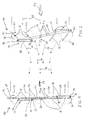
- Figures 1 to 7 show schematic side views a first embodiment of a generally designated 10 spoiler in different operating positions. It is in Figure 1, the spoiler 10 in the closed position shown while the figures 2 to 7 several, continuously adjustable opening positions represent the spoiler 10.
- the Air guiding device 10 can in particular in a Vehicle used.
- a driving device 12 which is a pushing element 42 in the form of a rectilinear, wobble pole and two with the same articulated coupling elements 38 has.
- a driving device 12 which is a pushing element 42 in the form of a rectilinear, wobble pole and two with the same articulated coupling elements 38 has.
- the coupling elements 38 are respectively two lamellae 14 in corresponding lamellar articulation points 34 hinged.
- Lamellenanlenkung at a respective, in or opposite the direction of the lamella (direction of rotation 28 of the two upper coupled slats 14 and Direction of rotation 30 of the two lower coupled Slats 14) projecting lamellar projection 36 realized.
- the lamella articulation points 34 are in this embodiment in Lamellenend Schemeen provided, wherein in the open position (FIGS 2 to 7), the lamella articulation points 34 of two upper, mutually coupled slats 14 in Reference to the corresponding plate pivot point 16 in a respective opposite slat area is located as the lamella articulation points 34 of the two lower, mutually coupled slats 14.
- the coupling elements 38 are at their Lamellenanlenkungsticianen 34 each at least along one Sector of a closed circular path 40 out.
- the driving device 12 are starting from the operating position of Figure 1, the upper two fins 14 according to the direction of rotation 28th pivoted about their respective pivot 16 while at the same time the lower two slats 14 in corresponding manner in the direction of rotation 30, the Direction of rotation 28 is opposite, pivoted become.
- a rotation of the blade 20 (middle Lamella 14) from its by a stop 44th defined closed position (vertical position according to Figure 1) in the direction of rotation 28 in a by a another stop 44 defined opening position ( Figures 2 to 7).
- Operating position of the fins 14 is thus a Air inlet flow (arrows 25) by means of such the spoiler 10 deflected that a in the Essentially converging air outlet flow (Arrows 26) is obtained.
- FIG. 4 shows a diverging air outlet flow 26 generated.
- FIG. 5 shows one by means of a further rotation the lamellae pairs according to arrow 28 or Arrow 30 adjustable operating position of the slats 14, wherein in this operating position the upper, slats coupled together in the closed position are positioned while the lower pair of slats in a substantially divergent one Air outlet flow (arrows 27) generating Operating position has taken.
- operating position is a reversal of direction of the lower pair of lamella, so that now both pairs of slats according to the arrows 28, the means to be turned in the same direction.
- this Operating position is thus the respective Lamella articulation point 34 of the lower, with each other coupled slats 14 in a defined Turning point 32.
- a subsequent Rotation of the upper and lower pairs of lamellae according to the arrows 28 are operating positions according to Figures 6 and 7 and air outlet flows Set according to the arrows 27.
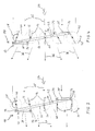
- FIGS 8 and 9 show a second, alternative Embodiment of a generally designated 10 Air guiding device 10.
- the air guiding device 10 has a driving device 12 in Shape of a step-shaped, longitudinally movable rod on.
- the according to double arrow 46 longitudinally movable rod 42 includes two guide longitudinal grooves 48 into which for rod movement guide a respective guide element a holder, not shown the spoiler 10 protrudes and selbiger is received longitudinally displaceable. Further contains the rod 42 for a respective articulation point 34 a corresponding guide transverse groove 50 for guidance a relative movement of a lamella connecting element with respect to the rod 42.
- the slats 14 of a respective pair of slats are at lamella articulation points 34 operatively connected to the rod 42, wherein the lamella articulation points 34 in different Distances to the associated sipes 16 lie.
- the Lamellenanlenkungscan 34 respectively along a sector of a closed circular path 40 led.
- FIG. 10 shows a schematic representation of a third embodiment of a generally designated 10 Spoiler device.
- the takeaway device 12 of this embodiment includes a Plurality of mutually hinged pushers 52, at each of which at least one blade 14 hinged is.
- the pushers 52 are in the form of rectilinear rods formed and by means of a actuatable drive element 54, the corresponding Double arrow 56 is pivotable, for Lamellenverschwenkung lagebewegbar. Again, there are the lamellar articulation points 34 at different intervals to the associated disk pivot points 16. Otherwise, the operation of the spoiler corresponds 10 according to FIG. 10 that of FIG Air guiding device according to the second embodiment ( Figure 9).
- FIG. 11 shows a fourth exemplary embodiment a generally designated 10 spoiler.
- the driving device 12 has two spaced apart lamellar linkage elements 58, each with an associated motion transfer element 60 in the form of a lever articulated are connected.
- the motion transmission elements 60 are by means of a double arrow 64 pivotable drive system 62 for Lamellenverschwenkung movable. This is a with the motion transmission elements 60 operatively connected common thrust element 66 in the form of a Rod provided.
- the lamellar linking elements 58 are in their Lamellenanschungsticianen 34 and in their articulation points 68 for the motion transmission elements 60 each at least along a sector of a closed circular path 40 out.
- This louver 10 allows a flexible setting of different air outlet profiles, for example, a divergent one Air outlet profile according to arrows 26.
- the other Operation of this spoiler 10 corresponds essentially those of those described above Embodiments.
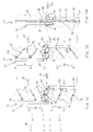
- Figures 12 to 14 show a schematic representation a fifth alternative embodiment an air guiding device 10, wherein in contrast not to the embodiment of FIG 11 a pushing element (rod 66), but a gear drive is provided.
- the motion transmission elements 60 for lamella adjustment respectively rotatably with an associated gear 70 of the gear drive connected, wherein the gears 70 with each other are coupled.
- One of the gears 70 is for example, with a servomotor, not shown operatively connected to generate a gearwheel rotation according to double arrow 72, by means of which a lamellar adjustment according to the figures 12, 13, 14 can be achieved.
- the air guiding device 10 according to FIGS. 12 to 14 corresponds with regard to FIG their constructive structure and their mode of operation essentially that of the spoiler 10 according to FIG. 11.
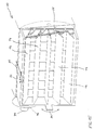
- FIG. 15 shows a schematic perspective view a spoiler 10 according to the Embodiment of Figures 1 to 7.
- the spoiler device 10 indicates the adjustment of the slats 14 both a servomotor 74 and a manual Adjustment 76 on.
- the slats 14 For this purpose, they are rotatable on a holding device 78 stored.
- the air guiding device 10 contains an adjustment 80, which corresponds to double arrow 82 is displaceable and a corresponding Rotation of rear, vertically arranged slats causes a corresponding vertical axis.
- the Adjustment 80 thus serves for lateral Direction change of the air flow (in the figure 15 a change of direction to the left or to right).
- a twist of the whole Air guiding device 10 according to double arrow 84 possible.
- the air guiding device 10 according to FIG 15 is thus characterized by a particularly flexible Adjustability of the air flow and the Air flow directions and the air passage profile out.
- the lamellar articulation elements 58 each having a rack sector, which engage with an associated gear, the gears being coupled together and by means of a servomotor are driven. It is too possible, instead of a rack sector, respectively provide toothed belts instead of a toothed rack, which engage with suitable gears.
- the device 10 according to the invention allows thus the use of a variety of different Drive systems for slat adjustment.
- an inventive Air deflector possible, not just one Direction change of an air jet, for example in a vehicle but at the same time also a targeted widening or narrowing of the Air jet to achieve. It can be beyond that Train effects in the vehicle interior are avoided because in a diffuse outflow of air from the Air deflector despite higher air volume no direct, as perceived by passengers as unpleasant Blowing occurs. In particular, it is possible a smooth closing of the spoiler to enable. Due to the flexible adjustability different air flow profiles at the outlet side of the spoiler is it possible to have a quick and effective cooling in a vehicle interior.
Landscapes
- Physics & Mathematics (AREA)
- Thermal Sciences (AREA)
- Engineering & Computer Science (AREA)
- Mechanical Engineering (AREA)
- Air-Flow Control Members (AREA)
- Specific Sealing Or Ventilating Devices For Doors And Windows (AREA)
Applications Claiming Priority (2)
| Application Number | Priority Date | Filing Date | Title |
|---|---|---|---|
| DE10130951 | 2001-06-27 | ||
| DE2001130951 DE10130951A1 (de) | 2001-06-27 | 2001-06-27 | Luftleitvorrichtung, insbesondere eines Fahrzeugs |
Publications (3)
| Publication Number | Publication Date |
|---|---|
| EP1270286A2 true EP1270286A2 (fr) | 2003-01-02 |
| EP1270286A3 EP1270286A3 (fr) | 2003-11-05 |
| EP1270286B1 EP1270286B1 (fr) | 2006-05-17 |
Family
ID=7689613
Family Applications (1)
| Application Number | Title | Priority Date | Filing Date |
|---|---|---|---|
| EP20020006728 Expired - Lifetime EP1270286B1 (fr) | 2001-06-27 | 2002-03-23 | Dispositif pour diriger l'air, notamment pour un véhicule |
Country Status (3)
| Country | Link |
|---|---|
| EP (1) | EP1270286B1 (fr) |
| DE (2) | DE10130951A1 (fr) |
| ES (1) | ES2262723T3 (fr) |
Cited By (6)
| Publication number | Priority date | Publication date | Assignee | Title |
|---|---|---|---|---|
| EP2046591A4 (fr) * | 2006-07-27 | 2010-04-21 | Collins & Aikman Prod Co | Fenetre d'aeration fournissant une diffusion |
| JP2017105401A (ja) * | 2015-12-11 | 2017-06-15 | トヨタ自動車株式会社 | 車両用レジスタ |
| CN108290476A (zh) * | 2015-11-30 | 2018-07-17 | 株式会社利富高 | 风向调整装置 |
| EP3409524A1 (fr) * | 2017-06-02 | 2018-12-05 | Flex-N-Gate Germany GmbH | Dispositif de contrôle du flux d'air dans un bloc moteur de véhicule automobile |
| CN110341439A (zh) * | 2019-07-09 | 2019-10-18 | 武汉舜宇模具有限责任公司 | 一种出风口导风结构及其安装方法 |
| CN112339529A (zh) * | 2019-08-09 | 2021-02-09 | 伊利诺斯工具制品有限公司 | 车辆通风结构中的空气导向叶片的操纵联接杆 |
Families Citing this family (10)
| Publication number | Priority date | Publication date | Assignee | Title |
|---|---|---|---|---|
| DE102006001798B4 (de) * | 2006-01-12 | 2018-05-09 | Mahle International Gmbh | Luftausströmer und Belüftungssystem mit einem Luftausströmer |
| DE102007019682A1 (de) * | 2007-04-24 | 2008-10-30 | Behr Gmbh & Co. Kg | Komfortdüse |
| DE102008016238A1 (de) * | 2008-03-27 | 2009-10-01 | Behr Gmbh & Co. Kg | Lüftdüse |
| DE102010014944B4 (de) * | 2010-04-14 | 2016-09-15 | Audi Ag | Vorrichtung zur Betätigung einer mechanischen Einrichtung |
| ES2774464T3 (es) | 2015-07-31 | 2020-07-21 | Weidplas Gmbh | Conjunto de trampillas de ventilación para un vehículo |
| DE102016214186A1 (de) | 2016-08-01 | 2018-02-01 | Volkswagen Aktiengesellschaft | Luftausströmer und Fahrzeug mit einem derartigen Luftausströmer |
| US10752088B2 (en) | 2016-12-09 | 2020-08-25 | Tesla, Inc. | Infotainment system with air-vent control |
| DE102018119639A1 (de) | 2018-08-13 | 2020-02-13 | Illinois Tool Works Inc. | Luftausströmer für ein Fahrzeug |
| DE102021125427A1 (de) | 2021-09-30 | 2023-03-30 | Illinois Tool Works Inc. | Luftausströmer für ein fahrzeug |
| DE102022105546A1 (de) | 2022-03-09 | 2023-09-14 | Dr. Ing. H.C. F. Porsche Aktiengesellschaft | Luftleitvorrichtung einer Kraftfahrzeugkarosserie eines Kraftfahrzeugs |
Citations (1)
| Publication number | Priority date | Publication date | Assignee | Title |
|---|---|---|---|---|
| US5591079A (en) | 1994-08-19 | 1997-01-07 | Honda Giken Kogyo Kabushiki Kaisha | Ventilation louver assembly, and methods of constructing and utilizing same |
Family Cites Families (9)
| Publication number | Priority date | Publication date | Assignee | Title |
|---|---|---|---|---|
| US3017899A (en) * | 1958-07-11 | 1962-01-23 | Elgen Mfg Corp | Swivel units and damper assemblies using same |
| US3084715A (en) * | 1959-12-31 | 1963-04-09 | Harry J Scharres | Damper assembly and blade construction |
| US3267962A (en) * | 1963-03-13 | 1966-08-23 | Elgen Mfg Corp | Damper assemblies |
| DE3628449A1 (de) * | 1986-08-21 | 1988-02-25 | Happich Gmbh Gebr | Luftleitvorrichtung |
| DE8816559U1 (de) * | 1988-09-26 | 1990-01-25 | Siemens AG, 1000 Berlin und 8000 München | Luftauslaß für Innenräume, insbesondere für den Innenraum eines Kraftfahrzeuges |
| DE4315220C1 (de) * | 1993-05-07 | 1994-05-05 | Bayerische Motoren Werke Ag | Luftausströmorgan für einen Fahrzeug-Innenraum |
| DE29817513U1 (de) * | 1998-10-01 | 1998-12-17 | OLHO-TECHNIK Oleff + Hoffmann oHG, 32584 Löhne | Lüftungsdüse |
| DE19910774C2 (de) * | 1999-03-11 | 2002-11-07 | Schneider Franz Kunststoffwerk | Fahrzeug-Frischluftdüseneinrichtung |
| DE19935338A1 (de) * | 1999-07-28 | 2001-02-01 | Volkswagen Ag | Luftausströmer mit Lamellen |
-
2001
- 2001-06-27 DE DE2001130951 patent/DE10130951A1/de not_active Withdrawn
-
2002
- 2002-03-23 DE DE50206780T patent/DE50206780D1/de not_active Expired - Lifetime
- 2002-03-23 ES ES02006728T patent/ES2262723T3/es not_active Expired - Lifetime
- 2002-03-23 EP EP20020006728 patent/EP1270286B1/fr not_active Expired - Lifetime
Patent Citations (1)
| Publication number | Priority date | Publication date | Assignee | Title |
|---|---|---|---|---|
| US5591079A (en) | 1994-08-19 | 1997-01-07 | Honda Giken Kogyo Kabushiki Kaisha | Ventilation louver assembly, and methods of constructing and utilizing same |
Cited By (10)
| Publication number | Priority date | Publication date | Assignee | Title |
|---|---|---|---|---|
| EP2046591A4 (fr) * | 2006-07-27 | 2010-04-21 | Collins & Aikman Prod Co | Fenetre d'aeration fournissant une diffusion |
| US7997964B2 (en) | 2006-07-27 | 2011-08-16 | International Automotive Components Group North America, Inc. | Air vent providing diffusion |
| CN108290476A (zh) * | 2015-11-30 | 2018-07-17 | 株式会社利富高 | 风向调整装置 |
| US10807442B2 (en) | 2015-11-30 | 2020-10-20 | Nifco Inc. | Wind direction adjustment device |
| CN108290476B (zh) * | 2015-11-30 | 2021-07-13 | 株式会社利富高 | 风向调整装置 |
| JP2017105401A (ja) * | 2015-12-11 | 2017-06-15 | トヨタ自動車株式会社 | 車両用レジスタ |
| EP3409524A1 (fr) * | 2017-06-02 | 2018-12-05 | Flex-N-Gate Germany GmbH | Dispositif de contrôle du flux d'air dans un bloc moteur de véhicule automobile |
| US10900409B2 (en) | 2017-06-02 | 2021-01-26 | Flex-N-Gate Germany Gmbh | Air flow control device for an engine block in a motor vehicle |
| CN110341439A (zh) * | 2019-07-09 | 2019-10-18 | 武汉舜宇模具有限责任公司 | 一种出风口导风结构及其安装方法 |
| CN112339529A (zh) * | 2019-08-09 | 2021-02-09 | 伊利诺斯工具制品有限公司 | 车辆通风结构中的空气导向叶片的操纵联接杆 |
Also Published As
| Publication number | Publication date |
|---|---|
| DE50206780D1 (de) | 2006-06-22 |
| EP1270286A3 (fr) | 2003-11-05 |
| ES2262723T3 (es) | 2006-12-01 |
| DE10130951A1 (de) | 2003-01-23 |
| EP1270286B1 (fr) | 2006-05-17 |
Similar Documents
| Publication | Publication Date | Title |
|---|---|---|
| EP2760685B1 (fr) | Diffuseur d'air d'un module de ventilation et de chauffage de véhicules automobiles, pouvant changer de position entre une position de focalisation et une position de diffusion | |
| EP0888916B1 (fr) | Système avec lamelles pour dispositifs d'aération pour régler la ventilation, notamment pour l'aération de véhicules à moteur | |
| EP3063026B1 (fr) | Diffuseur d'air | |
| EP3294579B1 (fr) | Dispositif de régulation d'un flux d'air | |
| DE4433698C1 (de) | Luftverteilungsvorrichtung | |
| DE19943822B4 (de) | Strömungsleitanordnung, insbesondere Ausströmgrill für Lüftungs- und Klimaanlagen von Kraftfahrzeugen | |
| EP1270286B1 (fr) | Dispositif pour diriger l'air, notamment pour un véhicule | |
| EP3530506B1 (fr) | Dispositif d'écoulement d'air | |
| DE202017102616U1 (de) | Luftausströmer zur Verwendung in einem Fahrzeug | |
| DE102012015519A1 (de) | Luftleitvorrichtung für eine Luftausströmvorrichtung eines Fahrzeugs | |
| DE102005027746A1 (de) | Luftausströmer für den Fahrgastraum eines Fahrzeuges | |
| DE10063189B4 (de) | Belüftungsvorrichtung | |
| DE102020131095A1 (de) | Lüftungseinrichtung | |
| EP1520738A1 (fr) | Aerateur à lamelles, en particulier pour climatisation de véhicule | |
| EP1457371B1 (fr) | Buse d'air, en particulier pour véhicules automobiles | |
| DE19711679B4 (de) | Vorrichtung und Verfahren zur Regelung einer Luftströmung | |
| DE102019116668A1 (de) | Ausströmdüse eines Kraftfahrzeugs | |
| EP0988165B1 (fr) | Buse de regulation d'ecoulement d'air pour l'aeration de l'habitacle d'un vehicule | |
| DE102007037273A1 (de) | Luftdüse zur Belüftung eines Fahrzeuginnenraums | |
| DE60016116T2 (de) | Lüftungsgitter, insbesondere für Kraftfahrzeuge | |
| DE102016122138A1 (de) | Luftausströmer | |
| DE69406326T2 (de) | Vorhang mit Strömungsregelung | |
| DE60208642T2 (de) | Fahrzeug-Klimaanlage mit flexiblem, plattenartigem Stellglied zur Regelung eines Luftstroms | |
| DE10135330A1 (de) | Antriebseinrichtung für Klappen zur Steuerung der Durchströmung der Luftleitkanäle einer Kraftfahrzeug-Heizungs- oder Klimaanlage | |
| DE102010035079A1 (de) | Luftausströmvorrichtung für ein Fahrzeug |
Legal Events
| Date | Code | Title | Description |
|---|---|---|---|
| PUAI | Public reference made under article 153(3) epc to a published international application that has entered the european phase |
Free format text: ORIGINAL CODE: 0009012 |
|
| AK | Designated contracting states |
Kind code of ref document: A2 Designated state(s): AT BE CH CY DE DK ES FI FR GB GR IE IT LI LU MC NL PT SE TR |
|
| AX | Request for extension of the european patent |
Free format text: AL;LT;LV;MK;RO;SI |
|
| PUAL | Search report despatched |
Free format text: ORIGINAL CODE: 0009013 |
|
| AK | Designated contracting states |
Kind code of ref document: A3 Designated state(s): AT BE CH CY DE DK ES FI FR GB GR IE IT LI LU MC NL PT SE TR |
|
| AX | Request for extension of the european patent |
Extension state: AL LT LV MK RO SI |
|
| 17P | Request for examination filed |
Effective date: 20040506 |
|
| AKX | Designation fees paid |
Designated state(s): DE ES FR IT |
|
| 17Q | First examination report despatched |
Effective date: 20040702 |
|
| RAP1 | Party data changed (applicant data changed or rights of an application transferred) |
Owner name: BEHR GMBH & CO. KG |
|
| GRAP | Despatch of communication of intention to grant a patent |
Free format text: ORIGINAL CODE: EPIDOSNIGR1 |
|
| GRAS | Grant fee paid |
Free format text: ORIGINAL CODE: EPIDOSNIGR3 |
|
| GRAA | (expected) grant |
Free format text: ORIGINAL CODE: 0009210 |
|
| AK | Designated contracting states |
Kind code of ref document: B1 Designated state(s): DE ES FR IT |
|
| PG25 | Lapsed in a contracting state [announced via postgrant information from national office to epo] |
Ref country code: IT Free format text: LAPSE BECAUSE OF FAILURE TO SUBMIT A TRANSLATION OF THE DESCRIPTION OR TO PAY THE FEE WITHIN THE PRESCRIBED TIME-LIMIT;WARNING: LAPSES OF ITALIAN PATENTS WITH EFFECTIVE DATE BEFORE 2007 MAY HAVE OCCURRED AT ANY TIME BEFORE 2007. THE CORRECT EFFECTIVE DATE MAY BE DIFFERENT FROM THE ONE RECORDED. Effective date: 20060517 |
|
| REF | Corresponds to: |
Ref document number: 50206780 Country of ref document: DE Date of ref document: 20060622 Kind code of ref document: P |
|
| REG | Reference to a national code |
Ref country code: ES Ref legal event code: FG2A Ref document number: 2262723 Country of ref document: ES Kind code of ref document: T3 |
|
| ET | Fr: translation filed | ||
| PLBE | No opposition filed within time limit |
Free format text: ORIGINAL CODE: 0009261 |
|
| STAA | Information on the status of an ep patent application or granted ep patent |
Free format text: STATUS: NO OPPOSITION FILED WITHIN TIME LIMIT |
|
| 26N | No opposition filed |
Effective date: 20070220 |
|
| PGFP | Annual fee paid to national office [announced via postgrant information from national office to epo] |
Ref country code: ES Payment date: 20080328 Year of fee payment: 7 |
|
| PGFP | Annual fee paid to national office [announced via postgrant information from national office to epo] |
Ref country code: IT Payment date: 20080318 Year of fee payment: 7 |
|
| PGFP | Annual fee paid to national office [announced via postgrant information from national office to epo] |
Ref country code: FR Payment date: 20080319 Year of fee payment: 7 |
|
| REG | Reference to a national code |
Ref country code: FR Ref legal event code: ST Effective date: 20091130 |
|
| PG25 | Lapsed in a contracting state [announced via postgrant information from national office to epo] |
Ref country code: FR Free format text: LAPSE BECAUSE OF NON-PAYMENT OF DUE FEES Effective date: 20091123 |
|
| REG | Reference to a national code |
Ref country code: ES Ref legal event code: FD2A Effective date: 20090324 |
|
| PG25 | Lapsed in a contracting state [announced via postgrant information from national office to epo] |
Ref country code: ES Free format text: LAPSE BECAUSE OF NON-PAYMENT OF DUE FEES Effective date: 20090324 |
|
| PG25 | Lapsed in a contracting state [announced via postgrant information from national office to epo] |
Ref country code: IT Free format text: LAPSE BECAUSE OF NON-PAYMENT OF DUE FEES Effective date: 20090323 |
|
| REG | Reference to a national code |
Ref country code: DE Ref legal event code: R082 Ref document number: 50206780 Country of ref document: DE Representative=s name: GRAUEL, ANDREAS, DIPL.-PHYS. DR. RER. NAT., DE |
|
| REG | Reference to a national code |
Ref country code: DE Ref legal event code: R082 Ref document number: 50206780 Country of ref document: DE Representative=s name: GRAUEL, ANDREAS, DIPL.-PHYS. DR. RER. NAT., DE Effective date: 20150311 Ref country code: DE Ref legal event code: R081 Ref document number: 50206780 Country of ref document: DE Owner name: MAHLE INTERNATIONAL GMBH, DE Free format text: FORMER OWNER: BEHR GMBH & CO. KG, 70469 STUTTGART, DE Effective date: 20150311 |
|
| PGFP | Annual fee paid to national office [announced via postgrant information from national office to epo] |
Ref country code: DE Payment date: 20190404 Year of fee payment: 18 |
|
| REG | Reference to a national code |
Ref country code: DE Ref legal event code: R119 Ref document number: 50206780 Country of ref document: DE |
|
| PG25 | Lapsed in a contracting state [announced via postgrant information from national office to epo] |
Ref country code: DE Free format text: LAPSE BECAUSE OF NON-PAYMENT OF DUE FEES Effective date: 20201001 |