EP1270336A2 - Boíte de fusibles et de relais dans un véhicule à moteur - Google Patents
Boíte de fusibles et de relais dans un véhicule à moteur Download PDFInfo
- Publication number
- EP1270336A2 EP1270336A2 EP02013315A EP02013315A EP1270336A2 EP 1270336 A2 EP1270336 A2 EP 1270336A2 EP 02013315 A EP02013315 A EP 02013315A EP 02013315 A EP02013315 A EP 02013315A EP 1270336 A2 EP1270336 A2 EP 1270336A2
- Authority
- EP
- European Patent Office
- Prior art keywords
- fuse
- cover
- relay box
- switching device
- electrical circuit
- Prior art date
- Legal status (The legal status is an assumption and is not a legal conclusion. Google has not performed a legal analysis and makes no representation as to the accuracy of the status listed.)
- Withdrawn
Links
Images


Classifications
-
- B—PERFORMING OPERATIONS; TRANSPORTING
- B60—VEHICLES IN GENERAL
- B60R—VEHICLES, VEHICLE FITTINGS, OR VEHICLE PARTS, NOT OTHERWISE PROVIDED FOR
- B60R16/00—Electric or fluid circuits specially adapted for vehicles and not otherwise provided for; Arrangement of elements of electric or fluid circuits specially adapted for vehicles and not otherwise provided for
- B60R16/02—Electric or fluid circuits specially adapted for vehicles and not otherwise provided for; Arrangement of elements of electric or fluid circuits specially adapted for vehicles and not otherwise provided for electric constitutive elements
- B60R16/023—Electric or fluid circuits specially adapted for vehicles and not otherwise provided for; Arrangement of elements of electric or fluid circuits specially adapted for vehicles and not otherwise provided for electric constitutive elements for transmission of signals between vehicle parts or subsystems
- B60R16/0238—Electrical distribution centers
Definitions
- the invention relates to a fuse and relay box for use in a motor vehicle. More particularly, the invention relates to a fuse and relay box for use in a motor vehicle having a switching device that opens or closes a vehicle electrical system connection to an electrical circuit.
- the fuse box is typically arranged inside the motor vehicle or in the engine compartment in such a way that it is easily accessible and may be opened to change a blown fuse.
- a new fuse is plugged in under load.
- fuses provided with connectors in the form of blade contacts
- arcing arises when the new fuse is inserted that can cause welding of contacts between the fuse and a receiving holder.
- the welding of the contacts between the fuse and the receiving holder can make the receiving holder unusable. In the case of relay boxes in particular, this can result in high costs.
- a fuse and relay box for a vehicle having an insulating housing, an electrical circuit and a switching device.
- the insulating housing having a cover that moves between an open position and a closed position.
- the electrical circuit is contained in the insulating housing, connected to a vehicle electrical system connection and has electrical components.
- the switching device opens or closes the connection between the vehicle electrical system connection and the electrical circuit depending on whether the cover is in the open position or the closed position.
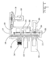
- Fig. 2 shows a fuse and relay box of a motor vehicle comprising an electrical circuit 5, an insulating housing 1 and a switching device 3.
- the electrical circuit 5 comprises a first printed circuit board 25 having a first pin trough 24 for a plug-in connector 23, a solder relay 22 and an element 21 with positive thermal coefficients (PTC).
- the first printed circuit board 25 is connected to a stamped grid stack 11.
- the stamped gird stock 11 is connected to a second printed circuit board 18 by a solder connection 16.
- a plug-in connector 12, a J-case fuse 13 and a mini fuse 14 with cross contacts 15 are arranged on the stamped grid stack 11.
- a second pin trough 19 for a printed circuit board (PCB) connector 20 is provided on the second printed circuit board 18.
- the second printed circuit board 18 is protected by a mechanical protection element 17.
- the electrical circuit 5 comprises electrical components which may be exchanged or plugged in by extraction and insertion, for example, the fuses 13 and the plug-in connector 12.
- the electrical circuit 5 also comprises fixed components that are not simply replaceable in the context of maintenance, for example, the solder relay 22.
- the electrical circuit 5 is illustrated with a a given combination of electrical components, the fuse and relay box may accommodate electrical circuits comprising any combination of electrical components. It is also not necessary for the fuse or the relay to be one of the electrical components.
- the housing 1 has an access cover 2 moveably mounted on a hinge 8.
- a limit stop 9 restricts the movement of the cover 2 to at least two open positions that are illustrated by dashed lines in Fig 2.
- the housing 1 conventionally consists of an electrically insulating material.
- the switching device 3 is connected with a motor vehicle electrical system via a battery supply line 6 and a motor vehicle electrical system connector 4. Shown in Figs 3 and 4, the switching device 3 has an input 35 and an output 34. A supply voltage of the vehicle electrical system is applied to the input 35 and may be connected with the electrical circuit 5 via the output 34, shown in Fig. 2.
- the switching device 3 has a switch housing 36, a contact bridge 33, a movable sensor element 31 and a restoring unit in the form of a spring 32.
- Fig. 4 shows the cover 2 in the closed position, whereby the cover 2 is positioned against the sensor element 31.
- the cover 2 acts on the sensor element 31 and the contact bridge 33 connected therewith to compress the spring 32 positioned against contacts (not shown) of the input 35 and the output 34 of the switching device 3.
- electrical connection between the electrical system connection 4 and the electrical circuit 5, shown in Fig. 2 is established.
- the spring 32 decompresses and acts on the sensor element 31 moving the sensor element 31 toward the position shown by the broken lines in Fig. 3.
- the positioning of the sensor element 31 is determined by the limit stop 37.
- the contact bridge 33 connected with the sensor element 31 is disconnected from the contacts (not shown) of the input 35 and the output 34 thereby disconnecting the electrical connection between the electrical system connection 4 and the electrical circuit 5. Because no voltage is applied to any of the electrical components of the electrical circuit 5, short-circuits caused by inadvertent contacting of conductive parts of the electrical circuit 5 are eliminated.
- Fig. 5 shows an alternative embodiment of the switching device of the fuse and relay box.
- the switching device 3 in Fig. 5 is coupled to a sensor element in the form of an ancillary switch 7, which may be arranged independently of the switching device 3.
- the ancillary switch 7 detects the open or closed position of the cover 3 and signals the position of the cover 2 to the switching device 3.
- the ancillary switch 7 may comprise, for example, a mechanical, electromechanical, inductive or optical type component.
- the ancillary switch 7 may detect the open or closed position of the cover 2 directly by contact with the cover 2 or by measuring the distance to the cover, or indirectly via the hinge 8.
- the ancillary switch 7 may accordingly be suitably arranged on or in the housing 1, on the electrical circuit 5 or the cover 2.
- connection to the electrical circuit 5 is connected or disconnected by the switching device 3.
- the electrical circuit 5 may also be designed so that only replaceable electrical components 13, 14 are disconnected from the motor vehicle electrical connection when the cover 2 is in an open position.
- a blown fuse 14 is detected from amongst a plurality of fuses 13, 14, selective disconnection of the affected fuses 14 or relevant areas in the electrical circuit 5 is also possible. In this way it is ensured that certain functions cannot be switched off in the motor vehicle, irrespective of whether the cover 2 is in the open position.
- the electrical circuit 5 may also be arranged on the cover 2 to simplify access to the electrical components.
- the switching device 3 may be arranged in the vicinity of the battery or on a supply line in the motor vehicle in order to isolate other electricity consuming devices in the motor vehicle from the electricity supply with one switching process.
- the switching device 3 could also be used by other electrical systems in the motor vehicle, for example, safety systems such as accident-detecting units, in order to be able to switch certain parts of the motor vehicle into a de-energised state.
- the switching device 3 may also be used to disconnect the battery during transportation of the vehicle.
- the cover may be replaced by any desired device that allows access to the fuse and relay box while protecting the fuse and relaty box from external influences.
- the cover could be a shutter or screen that may be removed completely or displaced for opening of the fuse and relay box.
- the walls of the fuse and relay box may be formed at least in part of bodywork parts or other parts of the motor vehicle. In this way, material and manufacturing costs for the fuse and relay box may be saved while achieving complete protection of the electrical circuit 5 against external mechanical influences.
Landscapes
- Engineering & Computer Science (AREA)
- Mechanical Engineering (AREA)
- Fuses (AREA)
- Switch Cases, Indication, And Locking (AREA)
- Mechanisms For Operating Contacts (AREA)
- Connection Or Junction Boxes (AREA)
Applications Claiming Priority (2)
| Application Number | Priority Date | Filing Date | Title |
|---|---|---|---|
| DE10130531 | 2001-06-25 | ||
| DE10130531 | 2001-06-25 |
Publications (2)
| Publication Number | Publication Date |
|---|---|
| EP1270336A2 true EP1270336A2 (fr) | 2003-01-02 |
| EP1270336A3 EP1270336A3 (fr) | 2004-05-19 |
Family
ID=7689333
Family Applications (1)
| Application Number | Title | Priority Date | Filing Date |
|---|---|---|---|
| EP02013315A Withdrawn EP1270336A3 (fr) | 2001-06-25 | 2002-06-18 | Boíte de fusibles et de relais dans un véhicule à moteur |
Country Status (4)
| Country | Link |
|---|---|
| US (1) | US20030022535A1 (fr) |
| EP (1) | EP1270336A3 (fr) |
| JP (1) | JP2003111240A (fr) |
| CA (1) | CA2389405A1 (fr) |
Cited By (1)
| Publication number | Priority date | Publication date | Assignee | Title |
|---|---|---|---|---|
| WO2012110138A1 (fr) * | 2011-02-16 | 2012-08-23 | Schaeffler Technologies AG & Co. KG | Dispositif de montage de commutateur d'interverrouillage, système haute tension pourvu d'un tel dispositif, et véhicule électrique ou hybride pourvu d'un dispositif de montage de commutateur d'interverrouillage et d'un système haute tension de ce type |
Families Citing this family (3)
| Publication number | Priority date | Publication date | Assignee | Title |
|---|---|---|---|---|
| KR101023885B1 (ko) * | 2008-11-27 | 2011-03-22 | 현대자동차주식회사 | 차량용 졍션 박스 |
| DE102012204792B4 (de) * | 2012-03-26 | 2022-10-20 | Schaeffler Technologies AG & Co. KG | Radnabenantrieb mit Interlockschalter an Felge |
| JP6893086B2 (ja) * | 2013-03-13 | 2021-06-23 | エーブリー デニソン コーポレイション | 接着特性の向上 |
Family Cites Families (13)
| Publication number | Priority date | Publication date | Assignee | Title |
|---|---|---|---|---|
| GB238963A (en) * | 1924-05-30 | 1925-08-31 | Reyrolle A & Co Ltd | Improvements in or relating to electric fuse boxes |
| GB463460A (en) * | 1936-01-03 | 1937-03-31 | Crabtree & Co Ltd J A | Improvements in, or relating to, electrical switch-fuse combinations |
| GB614681A (en) * | 1946-07-19 | 1948-12-20 | Arthur William Marshall Hartle | Improvements in and relating to electric junction and fuse boxes embodying switches |
| GB719849A (en) * | 1951-09-20 | 1954-12-08 | David Olof Hagglund | A combined electric fuse and contact breaker |
| US3940585A (en) * | 1974-05-13 | 1976-02-24 | Indak Manufacturing Corporation | Heavy duty push-button electrical switch |
| IT8121367U1 (it) * | 1981-04-02 | 1982-10-02 | Sace S P A Costr Elettromeccaniche | Interruttore elettrico |
| US4698727A (en) * | 1986-09-15 | 1987-10-06 | General Electric Company | Compact non-metallic load center enclosure |
| JPH0511331Y2 (fr) * | 1986-09-24 | 1993-03-19 | ||
| US5959271A (en) * | 1997-04-01 | 1999-09-28 | Metrol Co., Ltd. | Stopping device with a switch |
| US5949039A (en) * | 1997-10-20 | 1999-09-07 | Eastman Kodak Company | Service door interlock |
| US6494279B1 (en) * | 1998-06-11 | 2002-12-17 | Gnb Technologies, Inc. | Battery enclosure system for motive power in hazardous service environments |
| JP4226797B2 (ja) * | 2001-06-05 | 2009-02-18 | 住友電装株式会社 | 電気接続箱 |
| US6545861B1 (en) * | 2001-11-20 | 2003-04-08 | Fci Americas Technology, Inc. | High voltage distribution box with pre-molded lead frame |
-
2002
- 2002-06-04 US US10/162,032 patent/US20030022535A1/en not_active Abandoned
- 2002-06-05 CA CA002389405A patent/CA2389405A1/fr not_active Abandoned
- 2002-06-18 EP EP02013315A patent/EP1270336A3/fr not_active Withdrawn
- 2002-06-24 JP JP2002182354A patent/JP2003111240A/ja active Pending
Cited By (1)
| Publication number | Priority date | Publication date | Assignee | Title |
|---|---|---|---|---|
| WO2012110138A1 (fr) * | 2011-02-16 | 2012-08-23 | Schaeffler Technologies AG & Co. KG | Dispositif de montage de commutateur d'interverrouillage, système haute tension pourvu d'un tel dispositif, et véhicule électrique ou hybride pourvu d'un dispositif de montage de commutateur d'interverrouillage et d'un système haute tension de ce type |
Also Published As
| Publication number | Publication date |
|---|---|
| CA2389405A1 (fr) | 2002-12-25 |
| JP2003111240A (ja) | 2003-04-11 |
| EP1270336A3 (fr) | 2004-05-19 |
| US20030022535A1 (en) | 2003-01-30 |
Similar Documents
| Publication | Publication Date | Title |
|---|---|---|
| EP2465170B1 (fr) | Ensemble connecteur de fusible | |
| US4884050A (en) | Blade terminal tap fuse | |
| US7710236B2 (en) | Fuse systems with serviceable connections | |
| US6793510B2 (en) | Protecting device and method of shutting off a power supply | |
| EP1445839A1 (fr) | Systeme et procede permettant d'eviter la formation d'arcs electriques dans des connecteurs alimentant des charges de puissance et connecteur utilise | |
| JP5702314B2 (ja) | 切り替え可能なヒューズ付き配電ブロック | |
| EP1335471A2 (fr) | Relais à semi-conducteurs | |
| EP2993681B1 (fr) | Sectionneur mécanique avec protection de fusible intégrée | |
| CA2339394A1 (fr) | Fusible et porte-fusible | |
| KR20160134773A (ko) | 열적 안전 스위치 | |
| US20020182913A1 (en) | Electric connection box having a protecting function | |
| GB2333183A (en) | Battery disconnection system | |
| GB2117577A (en) | An electrical distributor segment for telephone exchange systems | |
| KR20060061813A (ko) | 자동차용 주파수 변환기 | |
| US6133645A (en) | Electronic device disconnect circuit | |
| US20030022535A1 (en) | Fuse and relay box in a motor vehicle | |
| US11636994B2 (en) | Attaching an isolated single stud fuse to an electrical device | |
| WO2006047231A2 (fr) | Relais relie a un fusible | |
| WO2024233472A1 (fr) | Module de sortie de puissance à haute tension pour un véhicule | |
| KR20110037217A (ko) | 고전압용 멀티 커넥터 | |
| US7355502B1 (en) | Direct relay connection to a fusible link | |
| EP4067174A1 (fr) | Conception de barre omnibus qui se termine avec un connecteur étanche | |
| US20070161276A1 (en) | Electrical entity with opening of the load current circuit in an explosion-vulnerable environment | |
| US20040079626A1 (en) | Smart/variable circuit breaker for automotive and other applications | |
| US4595842A (en) | Protection device for electronic components in vehicles |
Legal Events
| Date | Code | Title | Description |
|---|---|---|---|
| PUAI | Public reference made under article 153(3) epc to a published international application that has entered the european phase |
Free format text: ORIGINAL CODE: 0009012 |
|
| 17P | Request for examination filed |
Effective date: 20020618 |
|
| AK | Designated contracting states |
Kind code of ref document: A2 Designated state(s): AT BE CH CY DE DK ES FI FR GB GR IE IT LI LU MC NL PT SE TR |
|
| AX | Request for extension of the european patent |
Free format text: AL;LT;LV;MK;RO;SI |
|
| PUAL | Search report despatched |
Free format text: ORIGINAL CODE: 0009013 |
|
| AK | Designated contracting states |
Kind code of ref document: A3 Designated state(s): AT BE CH CY DE DK ES FI FR GB GR IE IT LI LU MC NL PT SE TR |
|
| AX | Request for extension of the european patent |
Extension state: AL LT LV MK RO SI |
|
| AKX | Designation fees paid |
Designated state(s): AT BE CH CY DE DK ES FI FR GB GR IE IT LI LU MC NL PT SE TR |
|
| 17Q | First examination report despatched |
Effective date: 20050204 |
|
| STAA | Information on the status of an ep patent application or granted ep patent |
Free format text: STATUS: THE APPLICATION IS DEEMED TO BE WITHDRAWN |
|
| 18D | Application deemed to be withdrawn |
Effective date: 20050615 |