EP1270382A2 - Agencement de bouclier pour le dessous d'un véhicule - Google Patents
Agencement de bouclier pour le dessous d'un véhicule Download PDFInfo
- Publication number
- EP1270382A2 EP1270382A2 EP02010790A EP02010790A EP1270382A2 EP 1270382 A2 EP1270382 A2 EP 1270382A2 EP 02010790 A EP02010790 A EP 02010790A EP 02010790 A EP02010790 A EP 02010790A EP 1270382 A2 EP1270382 A2 EP 1270382A2
- Authority
- EP
- European Patent Office
- Prior art keywords
- spring
- underside
- motor vehicle
- cladding
- spring element
- Prior art date
- Legal status (The legal status is an assumption and is not a legal conclusion. Google has not performed a legal analysis and makes no representation as to the accuracy of the status listed.)
- Granted
Links
Images


Classifications
-
- B—PERFORMING OPERATIONS; TRANSPORTING
- B62—LAND VEHICLES FOR TRAVELLING OTHERWISE THAN ON RAILS
- B62D—MOTOR VEHICLES; TRAILERS
- B62D25/00—Superstructure or monocoque structure sub-units; Parts or details thereof not otherwise provided for
- B62D25/20—Floors or bottom sub-units
- B62D25/2072—Floor protection, e.g. from corrosion or scratching
-
- B—PERFORMING OPERATIONS; TRANSPORTING
- B62—LAND VEHICLES FOR TRAVELLING OTHERWISE THAN ON RAILS
- B62D—MOTOR VEHICLES; TRAILERS
- B62D35/00—Vehicle bodies characterised by streamlining
- B62D35/02—Streamlining the undersurfaces
-
- Y—GENERAL TAGGING OF NEW TECHNOLOGICAL DEVELOPMENTS; GENERAL TAGGING OF CROSS-SECTIONAL TECHNOLOGIES SPANNING OVER SEVERAL SECTIONS OF THE IPC; TECHNICAL SUBJECTS COVERED BY FORMER USPC CROSS-REFERENCE ART COLLECTIONS [XRACs] AND DIGESTS
- Y02—TECHNOLOGIES OR APPLICATIONS FOR MITIGATION OR ADAPTATION AGAINST CLIMATE CHANGE
- Y02T—CLIMATE CHANGE MITIGATION TECHNOLOGIES RELATED TO TRANSPORTATION
- Y02T10/00—Road transport of goods or passengers
- Y02T10/80—Technologies aiming to reduce greenhouse gasses emissions common to all road transportation technologies
- Y02T10/88—Optimized components or subsystems, e.g. lighting, actively controlled glasses
Definitions
- the invention relates to a lining device for the underside of a Motor vehicle, according to the preamble of claim 1, and a motor vehicle with a Cladding device according to the preamble of claim 11.
- DE 32 39 946 A1 describes a generic covering device for the Underside of a motor vehicle known.
- This cladding device has a Trim part and for the trim part, a fastening device on the Underside, for example on an underbody of the vehicle, is held.
- the Fastening device has a plurality of spring elements, which are formed by tension springs are under tension on the underside of the vehicle and on the trim part be hooked in, with the tension direction of the tension spring running parallel to the underside.
- the cladding device can produce disturbing noises while the vehicle is traveling develop.
- the trim part when driving over a Obstacle by the attachment via the spring element in the direction of Dodge the underside of the vehicle, so that on the one hand there is a risk of dragging the Obstacle and on the other hand damage to the trim part is reduced becomes. If the road surface is soft and the vehicle sinks, there is also a targeted evasion of the trim part possible.
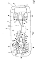
- Fig. 1 shows the underside 1 of a motor vehicle 2, which for example as Cars is trained.
- the motor vehicle 2 is in a preferred embodiment landforms. It comprises a front section 3, a middle section 4 and a rear section 5 the bottom 1, in particular on the middle part 4, has a so-called base group 6, which can extend to the front section 3 and the rear section 5 and an underbody Ub and has frame girders, of which sections only frame longitudinal girders Lt are shown.
- an exhaust system 7 is provided on the underside 1 Has muffler 8 and exhaust pipes 9. The front - seen in the direction of travel Fr. Exhaust pipes 9 lead to an internal combustion engine arranged in an engine compartment 10, which is not shown here.
- a transmission 11 is connected to the internal combustion engine flanged, which is attached at its free end to a transmission cross member Gt is attached to the bottom 1.
- the one or more cross members 13 In the area of the front section 3 is on the Bottom 1 attached to a subframe 12, the one or more cross members 13 and For example, has two side members 14, so that the subframe 12 - in plan view seen - is designed like a frame.
- the subframe 12 can be in one piece or be made in several parts. Chassis parts 15 are articulated to the subframe 12, which serve to accommodate wheels 16 of the front axle.
- a further subframe 17 is provided, which is arranged on the underside 1.
- chassis parts 18 To the rear subframe 17 chassis parts 18 are provided for wheels 19 which for Rear axle of the motor vehicle 2 belong.
- a cladding device 20 is arranged on the underside 1 of the vehicle has a trim part 21 and a fastening device 22 with which the Cover part 21 is held on the underside 1.
- the Covering part 21 covers engine compartment 10 from underside 1.
- the Covering part 21 extends, counter to the direction of travel Fr - to below the Transmission 11, preferably up to the transmission cross member Gt.
- the Covering part 21 tapers - seen in the direction of travel Fr - in its Width B and is thus to the opening contour of the engine compartment 10 and to the width of the Gear 11 adjusted.
- the width B is chosen so that a minimum distance is given to the exhaust system 7.
- the boundary edges Br des Trim part preferably to the course of the carrier of the subframe 12 customized.
- the trim part 21 between the side members 14 of the subframe 12 towards the underside 1 or underbody of the vehicle 2 is movable.
- the fastening device 22 for the trim part 21 has at least one Spring element 23 (Fig. 2), which between the bottom 1 and the trim part 21 is arranged.
- the spring element 23 is a bending spring 24, in particular Leaf spring, trained.
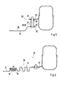
- one Fastening device 122 (Fig. 5), the spring element 23 by a compression spring 25, in particular helical spring formed.
- the spring forces of the spring element 23 act in Essentially approximately at right angles to the level of the underside 1, so that the trim part 21 lies at a distance from the underside 1 and counter to the force of the spring element 23 can dodge.
- the bending spring 24 extends transversely, in particular at right angles, to the direction of travel Fr and approximately parallel to the underside 1 and protrudes beyond the lateral boundary edges Br of the trim part 21.
- On The ends 27 and 28 projecting beyond the edges Br have the bending spring 24 in each case at least one curved spring region 29, 30 at its free end Fasteners or openings Db for the penetration of fasteners (not shown), so that the trim part 21 is attached to the underside 1 can be.
- the curved spring regions 29 and 30 overlap the longitudinal members 14 of subframe 12 between underside 1 and subframe 12, so that the free Ends 27 and 28 of the bending spring 24 can be attached to the underside 1.
- the spring element 23, in the exemplary embodiment according to FIG. 2, is the bending spring 24 attached approximately centrally in the area of the step transition 31 of the trim part 21, the thus tapers against the direction of travel Fr, preferably stepwise.
- the Fastening device 22 has, for example, further fastening means 32 which for example in the area of the front end 33 and rear end 34 on the Cover part 21 can be formed or attack it. For this you can Breakthroughs Db are also provided.
- the fasteners 32 preferably by rigid fasteners, such as for example, a screw or the like. Formed, reach through the openings Db and in the subframe 12 or the underside 1 are screwed in.
- the trim part 21 at its front end 33 by means of rigid Fastening means on the underside 1, preferably a carrier, for example Side member Lt or cross member, the frame or the floor assembly 6 is attached.
- a carrier for example Side member Lt or cross member
- the trim part 21 on the subframe 12, for example on one the cross member 13 are held.
- a second spring element 35 (FIG. 3) can be provided, which on the inside 26 of the Cover part 21 is present or is fixed there.
- the second spring element 35 is here formed, for example, as an approximately M-shaped leaf spring 36, which with its Base Ba is attached to the trim part 21.
- the free ends of the spring element 35 are fixed on the underside 1, in particular on the transmission cross member the fastening tabs 37 are provided for this purpose, at the free ends of the free Ends of the leaf spring 36 are attached. So that the trim part 21 to the Mounting tabs 37 can be moved past the corners of the Cover part 21 recesses 38 are provided.
- the Deformation element 41 consists, for example, of a deformable and / or compressible (foamed) material.
- Compression spring 25 is arranged through which a fastening screw 44 passes, the is fixed to the mounting bracket 37.
- the compression spring 25 is preferably supported on ring disks 45, which on the mutually facing surfaces of the Fastening tab 37 and the trim part 21 are.
- the fastening device 122 shown in FIG. 5 can also be on the middle one Area 46 of the trim part (FIG. 2) is provided in place of the bending spring 24 his.
- the mounting tabs 37 can be attached to the subframe 12.
- the compression springs 25 can also be located on the Support bottom 1, for example on the side members Lt of the frame or Bottom assembly 6.
- the bending spring 24 (Fig. 1) with its ends Support 27 and 28 on these side members Lt.
- a flexible intermediate piece 46 is provided, which with the rear end 34 of the trim part 21 and the fastening tab 37 is connected.
- the flexible element 46 can run in a meandering shape and on its straight line Ends with the trim part 21 and the fastening tab 37, in particular by Screws.
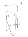
- a spring element 35 which is a leaf spring 48 realized and bent approximately V-shaped, with its free ends 49 and 50th on the one hand on the trim part 21 and on the other hand on the underside 1 or on the Gt crossmember fixed.
- the leaf spring 48 is oriented, for example, that their spring legs 51 and 52 lie approximately in or transverse to the direction of travel Fr.
- two leaf springs 48 are provided for the spring element 35, which in Vehicle transverse direction can lie side by side.
- the covering part 21 is thus such by means of the fastening device 22 or 122 attached to the underside 1 of the vehicle 2 towards the underside 1 can dodge if an obstacle is run over or the vehicle is in an area with soft surface sinks and thus the bottom 1 with this soft surface comes into contact. That which acts in particular as an aerodynamic fairing Cover part 21 is by the elastic suspension by means of Fastening device 22 and 122 protected from damage since it is in the direction of Bottom 1 or in the direction of the transmission 11 and that in the engine compartment 10 arranged engine can dodge.
- the trim device 20 includes a additional front trim part 53 (Fig. 1), which is in the direction of travel Fr before Cover part 21 is arranged on the underside 1. It can differ from a lower one Bumper or body end 54 up to the front end 33 of the trim part 21 extend.
- the front end 33 and the trim part preferably overlap 53 to a defined extent, so that with the fastening means 32 both Cover parts 21 and 53 are held.
- To connect trim part 53 with the bumper or body end 54 Conceivable is, however, the front trim part 53 with the fastening device 22 or 122 on the underside 1 and / or the subframe 12 and / or the end 54 Fasten.
- 53 for fastening the front trim part however, rigid fasteners such as screws are used.
- the fastening devices 22 and 122 described can also be used for other or other trim parts are used that are in other places on the bottom 1 can be attached.
- the trim part 21 can also be more Extend areas of the bottom 1.
- the fastening tabs 37 can otherwise can also be attached to the floor assembly 6.
- the trim parts 21 and 53 form an aerodynamic cover for the Underside 1.
- the front trim part 53 can be made of a solid Material, such as metal, be made and designed as underrun protection.
- the trim parts 21 and 53 can reduce the external vehicle noise have an inner surface facing the underside 1 with noise insulation.
Landscapes
- Engineering & Computer Science (AREA)
- Chemical & Material Sciences (AREA)
- Combustion & Propulsion (AREA)
- Transportation (AREA)
- Mechanical Engineering (AREA)
- Body Structure For Vehicles (AREA)
- Motor Or Generator Frames (AREA)
- Vehicle Interior And Exterior Ornaments, Soundproofing, And Insulation (AREA)
Applications Claiming Priority (2)
| Application Number | Priority Date | Filing Date | Title |
|---|---|---|---|
| DE10130358 | 2001-06-23 | ||
| DE10130358A DE10130358A1 (de) | 2001-06-23 | 2001-06-23 | Verkleidungsvorrichtung für die Unterseite eines Kraftfahrzeugs und Kraftfahrzeug |
Publications (3)
| Publication Number | Publication Date |
|---|---|
| EP1270382A2 true EP1270382A2 (fr) | 2003-01-02 |
| EP1270382A3 EP1270382A3 (fr) | 2004-01-02 |
| EP1270382B1 EP1270382B1 (fr) | 2008-01-30 |
Family
ID=7689218
Family Applications (1)
| Application Number | Title | Priority Date | Filing Date |
|---|---|---|---|
| EP02010790A Expired - Lifetime EP1270382B1 (fr) | 2001-06-23 | 2002-05-15 | Agencement de bouclier pour le dessous d'un véhicule |
Country Status (4)
| Country | Link |
|---|---|
| US (1) | US6726273B2 (fr) |
| EP (1) | EP1270382B1 (fr) |
| JP (1) | JP3756847B2 (fr) |
| DE (2) | DE10130358A1 (fr) |
Cited By (7)
| Publication number | Priority date | Publication date | Assignee | Title |
|---|---|---|---|---|
| EP1914151A1 (fr) * | 2006-10-18 | 2008-04-23 | Dr.Ing. h.c.F. Porsche Aktiengesellschaft | Soutien de collision dans la zone de tunnel d'un véhicule automobile |
| DE102014114092A1 (de) * | 2014-09-29 | 2016-03-31 | Dr. Ing. H.C. F. Porsche Aktiengesellschaft | Unterbodenverkleidung für ein Kraftfahrzeug |
| WO2017036583A1 (fr) * | 2015-09-02 | 2017-03-09 | Daimler Ag | Habillage du dessous de caisse d'un véhicule automobile, notamment d'un véhicule de tourisme |
| DE102016106569A1 (de) | 2016-04-11 | 2017-10-12 | Dr. Ing. H.C. F. Porsche Aktiengesellschaft | Unterbodenanordnung für ein Kraftfahrzeug |
| WO2020043450A1 (fr) * | 2018-08-30 | 2020-03-05 | Audi Ag | Composant d'habillage pour un composant d'essieu d'un véhicule |
| US20200070895A1 (en) * | 2018-08-31 | 2020-03-05 | Nissan North America, Inc. | Vehicle front-end assembly |
| FR3113023A1 (fr) | 2020-07-28 | 2022-02-04 | Renault S.A.S | Carénage comprenant des attaches flexibles |
Families Citing this family (32)
| Publication number | Priority date | Publication date | Assignee | Title |
|---|---|---|---|---|
| JP2003291860A (ja) * | 2002-04-05 | 2003-10-15 | Nippon Pop Rivets & Fasteners Ltd | 自動車の床裏のアンダーカバー取付装置 |
| DE10241883B4 (de) * | 2002-09-10 | 2012-06-21 | Andreas Stihl Ag & Co. | Handgeführtes Arbeitsgerät mit einem Befestigungsstift für einen Abgasschalldämpfer |
| US7055895B1 (en) * | 2004-06-04 | 2006-06-06 | John King | Protective plate assembly for land vehicle drive line and wheel differential |
| US7281597B2 (en) * | 2004-11-16 | 2007-10-16 | Ford Global Technologies, Llc | Fuel tank protector shield |
| US6962390B1 (en) * | 2004-11-23 | 2005-11-08 | General Motors Corporation | Hollow beams for incorporation in automotive vehicle frames |
| JP4697005B2 (ja) * | 2006-03-29 | 2011-06-08 | 三菱自動車工業株式会社 | 車体構造 |
| US7624835B2 (en) * | 2006-03-31 | 2009-12-01 | Honda Motor Company, Ltd. | Protective cover for the underside of a vehicle |
| JP4850573B2 (ja) * | 2006-04-24 | 2012-01-11 | ポップリベット・ファスナー株式会社 | アンダーカバー等の固定具及び取付装置 |
| US7506881B2 (en) * | 2006-08-30 | 2009-03-24 | Bfs Diversified Products Llc | Protective curtain for vehicle suspension components |
| DE102006041163A1 (de) * | 2006-09-01 | 2008-03-06 | Bayerische Motoren Werke Ag | Nachgiebige Abstützeinrichtung für ein Verkleidungsteil an der Unterseite eines Fahrzeugs |
| BRPI0823406B1 (pt) * | 2008-12-30 | 2018-12-18 | Volvo Lastvagnar Ab | disposição de motor para um veículo e veículo |
| US8028781B2 (en) * | 2009-04-21 | 2011-10-04 | Deere & Company | Flexible under-frame shield |
| FR2950852B1 (fr) * | 2009-10-06 | 2011-12-16 | Renault Sa | Dispositif de protection contre les chocs d'un organe de vehicule automobile monte sous caisse |
| NZ604962A (en) * | 2010-08-24 | 2014-06-27 | David Stuckey Invest Pty Ltd | Locking arrangement |
| MX2013006787A (es) * | 2011-02-17 | 2013-11-04 | Honda Motor Co Ltd | Cubiertas inferiores para corroceria de vehiculo. |
| DE102011018444A1 (de) * | 2011-04-21 | 2012-10-25 | Hs Genion Gmbh | Fahrzeug mit einem Unterboden |
| DE102011082060B4 (de) * | 2011-09-02 | 2023-08-31 | Bayerische Motoren Werke Aktiengesellschaft | Kraftfahrzeug mit einer Unterbodenverkleidung |
| DE102012018487A1 (de) * | 2012-09-17 | 2014-03-20 | GM Global Technology Operations LLC (n. d. Ges. d. Staates Delaware) | Unterbauverkleidung für ein Kraftfahrzeug |
| FR2997912B1 (fr) * | 2012-11-12 | 2016-04-01 | Renault Sas | Ecran aerodynamique inferieur de bouclier avant d'un vehicule automobile |
| US8839901B1 (en) | 2013-03-20 | 2014-09-23 | International Truck Intellectual Property Company, Llc | Transfer case skid shield |
| DE102013009256A1 (de) * | 2013-05-31 | 2014-12-04 | Audi Ag | Unterbodenverkleidung für ein Fahrzeug |
| JP6048682B2 (ja) * | 2014-03-27 | 2016-12-21 | マツダ株式会社 | 車両の前部車体構造 |
| JP6115524B2 (ja) * | 2014-07-16 | 2017-04-19 | マツダ株式会社 | 自動車の下部構造 |
| WO2016099435A1 (fr) * | 2014-12-15 | 2016-06-23 | Вадим Вячеславович БАШИЛИН | Carter de protection pour moteur d'automobile |
| JP6276334B2 (ja) | 2016-07-08 | 2018-02-07 | ヤマハモーターパワープロダクツ株式会社 | 車両 |
| DE102016214424A1 (de) * | 2016-08-04 | 2018-02-08 | Audi Ag | Achsanordnung für ein Fahrzeug |
| CN106741231A (zh) * | 2016-11-15 | 2017-05-31 | 朱晓义 | 一种汽车 |
| DE102017115206B4 (de) * | 2017-07-07 | 2022-01-05 | Dr. Ing. H.C. F. Porsche Aktiengesellschaft | Unterbodenverkleidung für ein Kraftfahrzeug |
| JP6946997B2 (ja) * | 2017-12-13 | 2021-10-13 | トヨタ自動車株式会社 | 車両用のオイルパンガード |
| US11945517B2 (en) * | 2022-02-16 | 2024-04-02 | Ford Global Technologies, Llc | Underbody panel with directed airflow |
| JP7361145B2 (ja) * | 2022-02-16 | 2023-10-13 | 本田技研工業株式会社 | 車両下部構造 |
| KR20240006907A (ko) * | 2022-07-07 | 2024-01-16 | 현대자동차주식회사 | 차량용 언더커버구조 |
Citations (1)
| Publication number | Priority date | Publication date | Assignee | Title |
|---|---|---|---|---|
| DE3239946A1 (de) | 1982-10-28 | 1984-05-03 | Daimler-Benz Ag, 7000 Stuttgart | Aerodynamische verkleidung fuer die unterseite von kraftwagen |
Family Cites Families (12)
| Publication number | Priority date | Publication date | Assignee | Title |
|---|---|---|---|---|
| US3279557A (en) * | 1964-04-15 | 1966-10-18 | Daniel W Halun | Protective cover for automobile underbody |
| US3454124A (en) * | 1967-08-02 | 1969-07-08 | Edward J Niedek | Motor vehicle drip absorption device with disposable element |
| US3776587A (en) * | 1972-02-14 | 1973-12-04 | K Oxlade | Surface vehicles with venturi attachment |
| US4445584A (en) * | 1978-04-12 | 1984-05-01 | Nissan Motor Co., Ltd. | Motor vehicle equipped with engine noise emission preventing device |
| JPS594818Y2 (ja) * | 1979-07-16 | 1984-02-13 | 本田技研工業株式会社 | 発熱部の車体への支持装置 |
| JPS5753925U (fr) * | 1980-09-16 | 1982-03-29 | ||
| US4655307A (en) * | 1985-05-06 | 1987-04-07 | Robert Lamoureux | Belly pan for four wheel all terrain vehicles |
| JPH0167183U (fr) * | 1987-10-27 | 1989-04-28 | ||
| JPH01171784U (fr) * | 1988-05-17 | 1989-12-05 | ||
| EP0888956B1 (fr) * | 1997-07-04 | 2002-08-14 | Volkswagen Aktiengesellschaft | Surface de dessous proche de l' essieu arrière pour véhicule automobile |
| GB2362360B (en) * | 1997-07-14 | 2002-01-09 | Land Rover Group Ltd | Motor vehicle undertray assemblies |
| JP3535047B2 (ja) * | 1999-07-16 | 2004-06-07 | 日産車体株式会社 | Ff車用アンダーカバー |
-
2001
- 2001-06-23 DE DE10130358A patent/DE10130358A1/de not_active Ceased
-
2002
- 2002-05-15 DE DE50211630T patent/DE50211630D1/de not_active Expired - Lifetime
- 2002-05-15 EP EP02010790A patent/EP1270382B1/fr not_active Expired - Lifetime
- 2002-06-04 JP JP2002162526A patent/JP3756847B2/ja not_active Expired - Fee Related
- 2002-06-21 US US10/175,895 patent/US6726273B2/en not_active Expired - Lifetime
Patent Citations (1)
| Publication number | Priority date | Publication date | Assignee | Title |
|---|---|---|---|---|
| DE3239946A1 (de) | 1982-10-28 | 1984-05-03 | Daimler-Benz Ag, 7000 Stuttgart | Aerodynamische verkleidung fuer die unterseite von kraftwagen |
Cited By (9)
| Publication number | Priority date | Publication date | Assignee | Title |
|---|---|---|---|---|
| EP1914151A1 (fr) * | 2006-10-18 | 2008-04-23 | Dr.Ing. h.c.F. Porsche Aktiengesellschaft | Soutien de collision dans la zone de tunnel d'un véhicule automobile |
| US8191670B2 (en) | 2006-10-18 | 2012-06-05 | Dr. Ing H.C.F. Porsche Aktiengesellschaft | Crash support in the tunnel region of a motor vehicle |
| DE102014114092A1 (de) * | 2014-09-29 | 2016-03-31 | Dr. Ing. H.C. F. Porsche Aktiengesellschaft | Unterbodenverkleidung für ein Kraftfahrzeug |
| WO2017036583A1 (fr) * | 2015-09-02 | 2017-03-09 | Daimler Ag | Habillage du dessous de caisse d'un véhicule automobile, notamment d'un véhicule de tourisme |
| DE102016106569A1 (de) | 2016-04-11 | 2017-10-12 | Dr. Ing. H.C. F. Porsche Aktiengesellschaft | Unterbodenanordnung für ein Kraftfahrzeug |
| WO2020043450A1 (fr) * | 2018-08-30 | 2020-03-05 | Audi Ag | Composant d'habillage pour un composant d'essieu d'un véhicule |
| US20200070895A1 (en) * | 2018-08-31 | 2020-03-05 | Nissan North America, Inc. | Vehicle front-end assembly |
| US10882568B2 (en) * | 2018-08-31 | 2021-01-05 | Nissan North America, Inc. | Vehicle front-end assembly |
| FR3113023A1 (fr) | 2020-07-28 | 2022-02-04 | Renault S.A.S | Carénage comprenant des attaches flexibles |
Also Published As
| Publication number | Publication date |
|---|---|
| DE10130358A1 (de) | 2003-01-09 |
| US6726273B2 (en) | 2004-04-27 |
| EP1270382A3 (fr) | 2004-01-02 |
| DE50211630D1 (de) | 2008-03-20 |
| EP1270382B1 (fr) | 2008-01-30 |
| JP2003011854A (ja) | 2003-01-15 |
| JP3756847B2 (ja) | 2006-03-15 |
| US20020195842A1 (en) | 2002-12-26 |
Similar Documents
| Publication | Publication Date | Title |
|---|---|---|
| EP1270382B1 (fr) | Agencement de bouclier pour le dessous d'un véhicule | |
| DE69808340T2 (de) | Kraftfahrzeug und dafür vorgesehene Bodenplatte zum Schutz des Motorblocks | |
| DE69705144T2 (de) | Verformbarer Aufhängungslenker für Kraftfahrzeuge | |
| DE19536460B4 (de) | Teilrahmen für ein Fahrzeug | |
| EP0941912B1 (fr) | Véhicule à moteur comportant un élément de renfort en forme de plaque | |
| DE69301923T2 (de) | Querteil für ein armaturenbrett für ein kraftfahrzeug | |
| DE4121263C2 (de) | Halterung für eine Hilfseinrichtung an einem Motor, insbesondere Kraftfahrzeugmotor | |
| EP0760327B1 (fr) | Structure d'un véhicule | |
| DE19732365B4 (de) | Schließbolzenanordnung für eine Heckklappe eines Steilheck-Fahrzeugs | |
| EP0291650B1 (fr) | Carénage aérodynamique pour le bas d'une automobile | |
| DE4035729A1 (de) | Dachtraeger fuer fahrzeuge | |
| EP3672818A1 (fr) | Pièce de recouvrement conçue pour un élément de train roulant d'un véhicule automobile | |
| DE102009003530B4 (de) | Befestigungssystem für einen Kraftfahrzeugspiegel | |
| DE4401023C1 (de) | Kraftfahrzeugvorbau | |
| DE4405904C1 (de) | Crashgünstige Aggregatlagerung | |
| DE102010033332A1 (de) | Unterbaustruktur für ein Kraftfahrzeug | |
| DE10036396B4 (de) | Fahrschemel-Modul für ein Kraftfahrzeug | |
| DE102019206517B4 (de) | Verkleidungsanordnung mit einem Fahrwerksteil in einer Fahrzeug-Radaufhängung | |
| DE10305652A1 (de) | Frontendbereich | |
| DE10347830B4 (de) | Anordnung einer Frontklappe an einem Fahrzeug | |
| EP1022211B1 (fr) | Véhicule aveec un chassis auxiliaire pour la suspension de roues | |
| DE102016204724B3 (de) | Anordnung eines Unterfahrschutzes an einem Vorderwagen eines Kraftfahrzeuges | |
| DE3035352A1 (de) | Vorderer kraftfahrzeug-endbereich | |
| DE102018222171B3 (de) | Anordnung einer Schutzstruktur für einen Montageträger in einem Vorderwagen eines Kraftfahrzeuges | |
| DE102009039807A1 (de) | Frontstruktur eines Kraftfahrzeugs |
Legal Events
| Date | Code | Title | Description |
|---|---|---|---|
| PUAI | Public reference made under article 153(3) epc to a published international application that has entered the european phase |
Free format text: ORIGINAL CODE: 0009012 |
|
| AK | Designated contracting states |
Kind code of ref document: A2 Designated state(s): AT BE CH CY DE DK ES FI FR GB GR IE IT LI LU MC NL PT SE TR |
|
| AX | Request for extension of the european patent |
Free format text: AL;LT;LV;MK;RO;SI |
|
| PUAL | Search report despatched |
Free format text: ORIGINAL CODE: 0009013 |
|
| AK | Designated contracting states |
Kind code of ref document: A3 Designated state(s): AT BE CH CY DE DK ES FI FR GB GR IE IT LI LU MC NL PT SE TR |
|
| AX | Request for extension of the european patent |
Extension state: AL LT LV MK RO SI |
|
| 17P | Request for examination filed |
Effective date: 20040702 |
|
| AKX | Designation fees paid |
Designated state(s): DE FR GB IT |
|
| GRAP | Despatch of communication of intention to grant a patent |
Free format text: ORIGINAL CODE: EPIDOSNIGR1 |
|
| GRAS | Grant fee paid |
Free format text: ORIGINAL CODE: EPIDOSNIGR3 |
|
| GRAA | (expected) grant |
Free format text: ORIGINAL CODE: 0009210 |
|
| AK | Designated contracting states |
Kind code of ref document: B1 Designated state(s): DE FR GB IT |
|
| REG | Reference to a national code |
Ref country code: GB Ref legal event code: FG4D Free format text: NOT ENGLISH |
|
| REF | Corresponds to: |
Ref document number: 50211630 Country of ref document: DE Date of ref document: 20080320 Kind code of ref document: P |
|
| GBT | Gb: translation of ep patent filed (gb section 77(6)(a)/1977) |
Effective date: 20080423 |
|
| RAP2 | Party data changed (patent owner data changed or rights of a patent transferred) |
Owner name: DR. ING. H.C. F. PORSCHE AKTIENGESELLSCHAFT |
|
| RAP2 | Party data changed (patent owner data changed or rights of a patent transferred) |
Owner name: DR. ING. H.C. F. PORSCHE AKTIENGESELLSCHAFT |
|
| ET | Fr: translation filed | ||
| PLBE | No opposition filed within time limit |
Free format text: ORIGINAL CODE: 0009261 |
|
| STAA | Information on the status of an ep patent application or granted ep patent |
Free format text: STATUS: NO OPPOSITION FILED WITHIN TIME LIMIT |
|
| 26N | No opposition filed |
Effective date: 20081031 |
|
| REG | Reference to a national code |
Ref country code: FR Ref legal event code: TP |
|
| REG | Reference to a national code |
Ref country code: FR Ref legal event code: CD |
|
| REG | Reference to a national code |
Ref country code: FR Ref legal event code: TP |
|
| REG | Reference to a national code |
Ref country code: GB Ref legal event code: 732E Free format text: REGISTERED BETWEEN 20110310 AND 20110316 |
|
| REG | Reference to a national code |
Ref country code: GB Ref legal event code: 732E Free format text: REGISTERED BETWEEN 20110331 AND 20110406 |
|
| REG | Reference to a national code |
Ref country code: FR Ref legal event code: PLFP Year of fee payment: 14 |
|
| REG | Reference to a national code |
Ref country code: FR Ref legal event code: PLFP Year of fee payment: 15 |
|
| PGFP | Annual fee paid to national office [announced via postgrant information from national office to epo] |
Ref country code: GB Payment date: 20160520 Year of fee payment: 15 |
|
| PGFP | Annual fee paid to national office [announced via postgrant information from national office to epo] |
Ref country code: IT Payment date: 20160524 Year of fee payment: 15 Ref country code: FR Payment date: 20160520 Year of fee payment: 15 |
|
| GBPC | Gb: european patent ceased through non-payment of renewal fee |
Effective date: 20170515 |
|
| REG | Reference to a national code |
Ref country code: FR Ref legal event code: ST Effective date: 20180131 |
|
| PG25 | Lapsed in a contracting state [announced via postgrant information from national office to epo] |
Ref country code: GB Free format text: LAPSE BECAUSE OF NON-PAYMENT OF DUE FEES Effective date: 20170515 |
|
| PG25 | Lapsed in a contracting state [announced via postgrant information from national office to epo] |
Ref country code: IT Free format text: LAPSE BECAUSE OF NON-PAYMENT OF DUE FEES Effective date: 20170515 Ref country code: FR Free format text: LAPSE BECAUSE OF NON-PAYMENT OF DUE FEES Effective date: 20170531 |
|
| PGFP | Annual fee paid to national office [announced via postgrant information from national office to epo] |
Ref country code: DE Payment date: 20210528 Year of fee payment: 20 |
|
| REG | Reference to a national code |
Ref country code: DE Ref legal event code: R071 Ref document number: 50211630 Country of ref document: DE |