EP1270392A2 - Moyeu de bicyclette pour disque de frein - Google Patents
Moyeu de bicyclette pour disque de frein Download PDFInfo
- Publication number
- EP1270392A2 EP1270392A2 EP02010868A EP02010868A EP1270392A2 EP 1270392 A2 EP1270392 A2 EP 1270392A2 EP 02010868 A EP02010868 A EP 02010868A EP 02010868 A EP02010868 A EP 02010868A EP 1270392 A2 EP1270392 A2 EP 1270392A2
- Authority
- EP
- European Patent Office
- Prior art keywords
- spoke
- attachment portion
- holes
- disc brake
- bicycle disc
- Prior art date
- Legal status (The legal status is an assumption and is not a legal conclusion. Google has not performed a legal analysis and makes no representation as to the accuracy of the status listed.)
- Granted
Links
Images






Classifications
-
- B—PERFORMING OPERATIONS; TRANSPORTING
- B60—VEHICLES IN GENERAL
- B60B—VEHICLE WHEELS; CASTORS; AXLES FOR WHEELS OR CASTORS; INCREASING WHEEL ADHESION
- B60B1/00—Spoked wheels; Spokes thereof
- B60B1/02—Wheels with wire or other tension spokes
- B60B1/04—Attaching spokes to rim or hub
- B60B1/041—Attaching spokes to rim or hub of bicycle wheels
-
- B—PERFORMING OPERATIONS; TRANSPORTING
- B60—VEHICLES IN GENERAL
- B60B—VEHICLE WHEELS; CASTORS; AXLES FOR WHEELS OR CASTORS; INCREASING WHEEL ADHESION
- B60B1/00—Spoked wheels; Spokes thereof
- B60B1/02—Wheels with wire or other tension spokes
- B60B1/04—Attaching spokes to rim or hub
- B60B1/042—Attaching spokes to hub
-
- B—PERFORMING OPERATIONS; TRANSPORTING
- B60—VEHICLES IN GENERAL
- B60B—VEHICLE WHEELS; CASTORS; AXLES FOR WHEELS OR CASTORS; INCREASING WHEEL ADHESION
- B60B1/00—Spoked wheels; Spokes thereof
- B60B1/02—Wheels with wire or other tension spokes
- B60B1/04—Attaching spokes to rim or hub
- B60B1/043—Attaching spokes to rim
- B60B1/044—Attaching spokes to rim by the use of spoke nipples
-
- B—PERFORMING OPERATIONS; TRANSPORTING
- B60—VEHICLES IN GENERAL
- B60B—VEHICLE WHEELS; CASTORS; AXLES FOR WHEELS OR CASTORS; INCREASING WHEEL ADHESION
- B60B21/00—Rims
- B60B21/02—Rims characterised by transverse section
- B60B21/04—Rims characterised by transverse section with substantially radial flanges
-
- B—PERFORMING OPERATIONS; TRANSPORTING
- B60—VEHICLES IN GENERAL
- B60B—VEHICLE WHEELS; CASTORS; AXLES FOR WHEELS OR CASTORS; INCREASING WHEEL ADHESION
- B60B27/00—Hubs
- B60B27/0005—Hubs with ball bearings
-
- B—PERFORMING OPERATIONS; TRANSPORTING
- B60—VEHICLES IN GENERAL
- B60B—VEHICLE WHEELS; CASTORS; AXLES FOR WHEELS OR CASTORS; INCREASING WHEEL ADHESION
- B60B27/00—Hubs
- B60B27/0047—Hubs characterised by functional integration of other elements
- B60B27/0052—Hubs characterised by functional integration of other elements the element being a brake disc
-
- B—PERFORMING OPERATIONS; TRANSPORTING
- B60—VEHICLES IN GENERAL
- B60B—VEHICLE WHEELS; CASTORS; AXLES FOR WHEELS OR CASTORS; INCREASING WHEEL ADHESION
- B60B27/00—Hubs
- B60B27/0078—Hubs characterised by the fixation of bearings
-
- B—PERFORMING OPERATIONS; TRANSPORTING
- B60—VEHICLES IN GENERAL
- B60B—VEHICLE WHEELS; CASTORS; AXLES FOR WHEELS OR CASTORS; INCREASING WHEEL ADHESION
- B60B27/00—Hubs
- B60B27/02—Hubs adapted to be rotatably arranged on axle
- B60B27/023—Hubs adapted to be rotatably arranged on axle specially adapted for bicycles
-
- F—MECHANICAL ENGINEERING; LIGHTING; HEATING; WEAPONS; BLASTING
- F16—ENGINEERING ELEMENTS AND UNITS; GENERAL MEASURES FOR PRODUCING AND MAINTAINING EFFECTIVE FUNCTIONING OF MACHINES OR INSTALLATIONS; THERMAL INSULATION IN GENERAL
- F16D—COUPLINGS FOR TRANSMITTING ROTATION; CLUTCHES; BRAKES
- F16D65/00—Parts or details
- F16D65/02—Braking members; Mounting thereof
- F16D65/12—Discs; Drums for disc brakes
- F16D65/123—Discs; Drums for disc brakes comprising an annular disc secured to a hub member; Discs characterised by means for mounting
-
- F—MECHANICAL ENGINEERING; LIGHTING; HEATING; WEAPONS; BLASTING
- F16—ENGINEERING ELEMENTS AND UNITS; GENERAL MEASURES FOR PRODUCING AND MAINTAINING EFFECTIVE FUNCTIONING OF MACHINES OR INSTALLATIONS; THERMAL INSULATION IN GENERAL
- F16D—COUPLINGS FOR TRANSMITTING ROTATION; CLUTCHES; BRAKES
- F16D65/00—Parts or details
- F16D65/02—Braking members; Mounting thereof
- F16D2065/13—Parts or details of discs or drums
- F16D2065/134—Connection
- F16D2065/1348—Connection resilient
-
- F—MECHANICAL ENGINEERING; LIGHTING; HEATING; WEAPONS; BLASTING
- F16—ENGINEERING ELEMENTS AND UNITS; GENERAL MEASURES FOR PRODUCING AND MAINTAINING EFFECTIVE FUNCTIONING OF MACHINES OR INSTALLATIONS; THERMAL INSULATION IN GENERAL
- F16D—COUPLINGS FOR TRANSMITTING ROTATION; CLUTCHES; BRAKES
- F16D65/00—Parts or details
- F16D65/02—Braking members; Mounting thereof
- F16D2065/13—Parts or details of discs or drums
- F16D2065/134—Connection
- F16D2065/1384—Connection to wheel hub
Definitions
- This invention generally relates to a bicycle disc brake hub. More specifically, the present invention relates a bicycle disc brake hub with an integral rotor attachment portion or flange.
- Bicycling is becoming an increasingly popular form of recreation as well as a means of transportation. Moreover, bicycling has become a very popular competitive sport. Whether the bicycle is used for recreation, transportation or competition, the bicycle industry is constantly improving their components. Recently, the braking systems for bicycles have included the use of disc brakes. The use of disc brakes has resulted in modifications to the bicycle hub of the bicycle wheel so that a brake rotor can be mounted thereon.
- the most basic bicycle wheels have a hub, a plurality of spokes and an annular rim.
- the hub is attached to a part of the frame of the bicycle for relative rotation.
- the inner ends of the spokes are coupled to the hub and extend outwardly from the hub.
- the annular rim is coupled to the outer ends of the spokes and has an outer portion for supporting a pneumatic tire thereon.
- the spokes of the bicycle wheel are thin metal wire spokes.
- the ends of the hub are provided with a flange that is used to couple the spokes to the hub. In particular, holes are provided in the hub flanges.
- the wire spokes are usually bent on their inner end and provided with an enlarged head or flange that is formed in the shape of a nail head.
- the inner end is supported in one of the holes in one of the hub flanges.
- the outer ends of the spokes typically are provided with threads for engaging spoke nipples, which secure the outer ends of the wire spokes to the rim.
- the spoke nipples have flanges, which engage the interior surface of the rim.
- the nipples are installed in nipple holes formed in the rim.
- the spokes are inserted sideways through the holes in the hub flange until the enlarged head or flanges of the spokes engaging the areas surrounding the holes in the hub flange.
- the male threads on the ends of the spokes are threaded into the female threads of the spoke nipples installed in the openings of the rim.
- the hub When the hub is a disc brake hub, installation and/or replacement of the spokes can be difficult.
- one end of the hub usually has a brake rotor attachment portion.
- the brake rotor attachment portion is a plurality of blind bores that receive bolts to directly mount the disc brake rotor to the end of the hub.
- the disc brake rotor makes it difficult to insert the spokes in a sideways direction.
- the spoke attachment portion adjacent the brake rotor attachment portion is often made to be larger in diameter than the brake rotor attachment portion. This increases the weight of the disk brake hub as well as the cost to manufacture the disk brake hub.
- hubs that have blind bores for mounting a disc brake rotor are time consuming to form and often become damaged. When the blind bores become damaged, the entire hub must be replaced. Thus, these prior hubs are expensive to manufacture and replace.
- One object of the present invention is to provide a bicycle hub with an integrated brake rotor attachment portion disposed adjacent the first spoke attachment portion such spokes can easily be installed into first spoke holes of the first spoke attachment portion.
- Another object of the present invention is to provide a bicycle hub with an integrated brake rotor attachment portion disposed adjacent the first spoke attachment portion that is relatively lightweight.
- Another object of the present invention is to provide a bicycle hub with an integrated brake rotor attachment portion disposed adjacent the first spoke attachment portion that is relatively inexpensive to manufacture.
- a bicycle disc brake hub comprising a hub axle, a hub shell, a first spoke attachment portion, a second spoke attachment portion and a brake rotor attachment portion.
- the hub axle has a center axis extending in an axial direction between a first axle end and a second axle end.
- the hub shell has an interior passageway extending between first and second hub shell ends with the hub axle being rotatably supported in the interior passageway.
- the first spoke attachment portion has a plurality of first spoke holes extending axially between the first and second axially facing surfaces. The first spoke holes have center axes spaced a first radial distance from the center axis of the hub axle.
- the first spoke attachment portion is disposed at the first hub shell end with the second axially facing surface facing towards the second hub shell end.
- the second spoke attachment portion has a plurality of second spoke holes.
- the second spoke attachment portion is disposed at the second hub shell end.
- the brake rotor attachment portion has a plurality of axially extending rotor mounting holes with predetermined diameters and center axes spaced a second radial distance from the center axis of the hub axle.
- the brake rotor attachment portion is disposed adjacent the first spoke attachment portion with the first axially facing surface facing towards the brake rotor attachment portion.
- the first spoke attachment portion and the brake rotor attachment portion are arranged relative to each other to attach spokes to the first spoke holes through the rotor mounting holes of the brake rotor attachment portion.
- the first spoke holes are individually viewable in the axial direction from a location looking axially towards the brake rotor attachment portion.
- the first axially facing surface of the first spoke attachment portion and the first radial distance of the first spoke holes are less than the second radial distance plus half of the predetermined diameter of one of the rotor mounting holes.
- a bicycle disc brake hub comprising a hub axle, a hub shell, a first spoke attachment portion, a second spoke attachment portion and a brake rotor attachment portion.
- the hub axle has a center axis extending in an axial direction between a first axle end and a second axle end.
- the hub shell has an interior passageway extending between first and second hub shell ends with the hub axle being rotatably supported in the interior passageway.
- the first spoke attachment portion has a plurality of first spoke holes extending axially between the first and second axially facing surfaces. The first spoke attachment portion being disposed at the first hub shell end with the second axially facing surface facing towards the second hub shell end.
- the second spoke attachment portion has a plurality of second spoke holes, the second spoke attachment portion being disposed at the second hub shell end.
- the brake rotor attachment portion has a plurality of axially extending rotor mounting holes and an outer peripheral surface that lies within an imaginary circle circumscribing the outer peripheral surface.
- the brake rotor attachment portion is disposed adjacent the first spoke attachment portion with the first axially facing surface facing towards the brake rotor attachment portion.
- the first spoke holes is located radially inward of the imaginary circle circumscribing the outer peripheral surface of the brake rotor attachment portion.
- a bicycle disc brake hub comprising a hub axle, a hub shell, a first spoke attachment portion, a second spoke attachment portion and a brake rotor attachment portion.
- the hub axle has a center axis extending in an axial direction between a first axle end and a second axle end.
- the hub shell has an interior passageway extending between first and second hub shell ends with the hub axle being rotatably supported in the interior passageway.
- the first spoke attachment portion has a plurality of first spoke holes extending axially between the first and second axially facing surfaces.
- the first spoke attachment portion is disposed at the first hub shell end with the second axially facing surface facing towards the second hub shell end.
- the second spoke attachment portion has a plurality of second spoke holes.
- the second spoke attachment portion being disposed at the second hub shell end.
- the brake rotor attachment portion has a plurality of axially extending rotor mounting holes.
- the brake rotor attachment portion is disposed adjacent the first spoke attachment portion with the first axially facing surface facing towards the brake rotor attachment portion.
- the brake rotor attachment portion and the first spoke attachment portion have maximum outer diameters with the maximum outer diameter of the first spoke attachment portion being no greater than the maximum outer diameter of the brake rotor attachment portion.
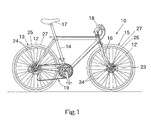
- a bicycle 10 is illustrated with rear and front disc brake hubs 12 and 12' in accordance with a first embodiment of the present invention as discussed below.
- the rear disc brake hub 12 rotatably couples a rear wheel 13 to a rear portion of a frame 14 of the bicycle 10, while the front disc brake hub 12' rotatably couples a front wheel 15 to a front fork 16 of the frame 14.
- the frame 14 also includes a seat 17 adjustably coupled to the frame 14, a handlebar 18 coupled to the front fork 16 for turning the front wheel 15 and a drive train 19 for propelling the bicycle 10.
- the bicycle 10 is also provided with rear and front disc brake assemblies 20 and 20'.
- the rear disc brake assembly 20 includes a caliper 21 operatively coupled to a brake lever 22 and a rear disc brake rotor 23 fixedly coupled to the rear disc brake hub 12 of the rear wheel 13.
- the front disc brake assembly 20' includes a caliper 21' operatively coupled to a brake lever 22' and a front disc brake rotor 23 (same as rear rotor) fixedly coupled to the front disc brake hub 12' of the front wheel 15.
- the rear and front disc brake hubs 12 and 12' of the and front wheels 13 and 15 have a plurality of spokes 24 extending outwardly therefrom.
- the outer ends of the spokes 24 are fixedly coupled to the rim 25 by spoke nipples 26.
- a tire 27 is located on the outer surface of each of the rims 25 in ac conventional manner.
- the disc brake rotors 23 are attached to the rear and front disc brake hubs 12 and 12' by bolts 28, as explained below.
- the spokes 24, the rims 25 and the spoke nipples 26 are all conventional parts that are used with the rear and front disc brake hubs 12 and 12' of the present invention.
- the unique design of the rear and front disc brake hubs 12 and 12' allows it to be used with conventional parts, e.g., conventional tangential spokes 24 and conventional rims 25. Accordingly, when the wheels 13 and 15 are assembled, the spokes 24 extend tangentially from imaginary circles centered on the center axes of rotations O and O' of the rear and front disc brake hubs 12 and 12', respectively.
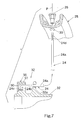
- spokes are spokes that have a straight section 24a and a bent end 24b with an enlarged head 24c such that straight section 24a extends at an angle of about 95° relative to the bent end 24b as seen in Figure 7.
- spokes are well known in the bicycle art. While the spokes 24 are illustrated as being tangentially arranged relative to the rear and front disc brake hubs 12 and 12', it will be apparent to those skilled in the art from this disclosure that other spoke arrangements are possible without departing from the present invention. For example, one end or both ends of the rear and front disc brake hubs 12 and 12' can have radially extending spokes.
- the spokes 24 of the illustrated embodiment each have an outer threaded end 24d that is located at the opposite end of the center straight section 24a from the bent end 24b (inner end portion) with the enlarged head 24c.
- the bent end 24b has a center axis that forms an angle of about 95° with the center axis of the straight section 24a.
- the bent ends 24b of the spokes 24 are designed to be received within the first and second spoke holes.
- the rim 25 can be any conventional rim that has a plurality of spoke holes 30 for receiving the spoke nipples 26 for attaching the outer threaded ends 24d of the spokes 24 thereto.
- the rims 25 for the rear and front disc brake hubs 12 and 12' are conventional steel or alloy rims having a U-shaped cross section with twenty-four spoke holes 30.
- the spoke holes 30 are equally spaced apart in a circumferential direction.
- the spoke holes 30 are preferably lie in a single plane P that divides the cross section in half as seen in Figure 7.
- rims with fewer or more spoke holes 30 can be used with a hub of the present invention, if needed and/or desired.
- the rims 25 can have thirty-two or thirty-six spoke holes instead of twenty-four spoke holes, if the rear and front disc brake hubs 12 and 12' are modified to have more spoke holes as explained below.
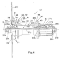
- the bicycle disc brake hub 12 basically comprising a hub axle 31, a hub shell 32, a first spoke attachment portion 33, a second spoke attachment portion 34 and a brake rotor attachment portion 35.
- the bicycle disc brake hub 12 is basically a conventional hub, except for the configuration of the hub shell 32, the first spoke attachment portion 33 and the brake rotor attachment portion 35.
- conventional parts of the bicycle disc brake hub 12 will not illustrated and/or discussed in detail herein.
- the hub axle 31 has a center axis O extending in an axial direction between a first axle end 31a and a second axle end 31b.
- the hub axle 31 has a center bore 31c such that a quick release mechanism (not shown) is coupled to the hub axle 31 in a conventional manner.
- the hub axle 31 rotatably supports the hub shell 32 by first and second bearing assemblies 36a and 36b.
- the second axle end 31b has a freewheel 37 operatively coupled between the hub axle 31 and the hub shell 32 in a conventional manner.
- the hub shell 32 is fixed with respect to the hub axle 31 in one rotational direction by the freewheel 37, while the freewheel 37 allows the hub shell 32 to freely rotate with respect to the hub axle 31 in the opposite rotational direction.
- the first and second ends 31a and 31b of the hub axle 31 are threaded for receiving a pair of nuts 39a and 39b that applies an axial force on the hub shell 32, the bearing assemblies 36a and 36b and the freewheel 37.
- the hub shell 32 is a tubular member that has an interior passageway 40 extending between first and second hub shell ends 32a and 32b with the hub axle 31 being rotatably supported in the interior passageway 40.
- the first and second bearing assemblies 36a and 36b rotatably mount the hub shell 32 within the interior passageway 40.
- the hub shell 32 also has a center tubular portion 32c located between the first and second hub shell ends 32a and 32b, which are integral formed with the center tubular portion 32c as a one-piece, unitary member.
- the first and second spoke attachment portions 33 and 34 and the brake rotor attachment portion 35 are integrally formed with the hub shell 32 as a one-piece, unitary member.
- the first hub shell end 32a has the first spoke attachment portion 33 and the brake rotor attachment portion 35 integrally mounted thereon
- the second hub shell end 32b has the second spoke attachment portion 34 integrally mounted thereon.
- the second hub shell end 32b has the freewheel 37 fixedly coupled thereto.
- the freewheel 37 is attached between the second hub shell end 32b and the second axle end 31b to allow the hub axle 31 to rotate freely relative to the hub shell 32 in one direction, but fixedly couples the hub axle 31 relative to the hub shell 32 in the opposite rotational direction.
- the bearing assemblies 36a and 36b rotatably support the hub shell 32 on the hub axle 31. Since the bearing assemblies 36a and 36b are well known in the bicycle art, they will not be discussed or illustrated in detail herein.
- the bearing assembly 36a basically includes a plurality of balls located between an inner race member and an outer race member in a conventional manner.
- the bearing assembly 36b basically includes a plurality of balls located between an inner race member and an outer race member in a conventional manner.
- Bicycle freewheels such as the freewheel 37
- the freewheel 37 is used to transmit a driving force from the chain to the rear bicycle wheel in one rotation direction only.
- the freewheel 37 allows the bicycle 10 to advance freely without any rotation of the pedals.
- the freewheel 37 is fastened to the rear hub 12 as integral part of the rear hub 12 in a conventional manner.
- the freewheel 37 basically includes an outer tubular part 37a, an inner tubular part 37b and a one-way clutch 37c.
- the inner tubular part 37b is installed radially inwardly of the outer tubular part 37a so that the inner tubular part 37b is free to rotate relative to the outer tubular part 37a.
- the one-way clutch 37c is installed between the outer tubular part 37a and inner tubular part 37b for transmitting the driving force from the outer tubular part 37a to the inner tubular part 37b in one rotational direction only.
- the outer tubular part 37a has a plurality of gears or sprockets (not shown) mounted thereon, while the inner tubular part 37b is fixedly mounted on the hub axle 31.
- the first spoke attachment portion 33 is preferably an annular spoke flange located at the first hub shell end 32a of the hub shell 32.
- the first spoke attachment portion 33 has a plurality of first spoke holes 43.
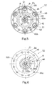
- the first spoke attachment portion 33 has twelve of the first spoke holes 43 equally spaced apart about an imaginary circle C 1 that is centered about the center axis O.
- the first spoke holes 43 are arranged to receiving the bent ends 24b of the spokes 24.
- the first spoke holes 43 have their center axes A parallel to the center axis O of the hub axle 31.
- the first spoke holes 43 lie on the imaginary circle C 1 that is centered on the center axis O of the hub axle 31.
- the first spoke attachment portion 33 has a first (outer) axially facing surface 41 and a second (inner) axially facing surface 42 with the first spoke holes 43 extending axially between the first (outer) axially facing surface 41 and the second (inner) axially facing surface 42.
- the first spoke attachment portion 33 is disposed at the first hub shell end 32a with the second axially facing surface 42 facing towards the second hub shell end 32b.
- the first spoke holes 43 have their center axes A spaced a first radial distance R 1 from the center axis O of the hub axle 31.
- each of the first spoke holes 43 has a transverse cross section with a semi circular section 43a and a notched section 43b that extends outwardly from the semi circular section 43a in a radial direction relative to its center axis A.
- This shape of the first spoke holes 43 allows for easy insertion of the spokes 24 into the first spoke holes 43 during assembly of the spokes 24 to the bicycle disc brake hub 12.
- the semi circular section 43a preferably extends at least about 180° and more preferably about 300° to securely retain the bent ends 24b of the spokes 24 therein.
- the notched section 43b preferably extends outwardly at least about half of the diameter of the semi circular section 43a from the circumference of the circle defining the second semi circular section 43a.
- the notched sections 43b of the first spoke holes 43 are oriented so that every other one of the notched sections 43b points towards the center axis O of the hub axle 31, while other notched sections 43b point in a circumferential direction.
- the second hub shell end 32b of the hub shell 32 is provided with a plurality of second spoke holes 44 for receiving the bent ends 24b of the spokes 24.
- the second hub shell end 32b is provided with twelve of the second spoke holes 44 equally spaced apart about the imaginary circle C 1 that is centered on the center axis O of the hub axle 31.
- Each of the spoke holes 44 is also designed to receive one of the bent ends 24b of the spokes 24.
- the rear hub 12 is designed to have twenty-four spokes extending outwardly therefrom in a generally tangential direction.
- the second spoke attachment portion 34 is preferably an annular spoke flange located at the second hub shell end 32b of the hub shell 32.
- the second spoke holes 44 have their center axes A parallel to the center axis O of the hub axle 31.
- the second spoke holes 44 lie on the imaginary circle C 1 centered on the center axis O of the hub axle 31.
- the second spoke attachment portion 34 has a first (outer) axially facing surface 45 and a second (inner) axially facing surface 46 with the second spoke holes 44 extending axially between the first (outer) axially facing surface 45 and the second (inner) axially facing surface 46.
- the second spoke attachment portion 34 is disposed at the second hub shell end 32b with the second axially facing surface 46 facing towards the first hub shell end 32a.
- the second spoke holes 44 have their center axes A spaced a radial distance R 1 from the center axis O of the hub axle 31.
- the center axes A of the second spoke holes 44 are circumferentially offset from the center axes A of the first spoke holes 43 such that the spoke holes 43 are located between the spoke holes 44.
- each of the second spoke holes 44 has a transverse cross section with a semi circular section 44a and a notched section 44b that extends outwardly from the semi circular section 44a in a radial direction relative to its center axis A.
- This shape of the second spoke holes 44 allows for easy insertion of the spokes 24 into the second spoke holes 44 during assembly of the spokes 24 to the bicycle disc brake hub 12.
- the semi circular section 44a preferably extends at least about 180° and more preferably about 300° to securely retain the bent ends 24b of the spokes 24 therein.
- the notched section 44b preferably extends outwardly at least about half of the diameter of the semi circular section 44a from the circumference of the circle defining the semi circular section 44a.
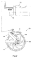
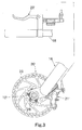
- the first and second spoke holes 43 and 44 are identical in cross section, but have different orientations of the notched sections 43b and 44b as seen in Figures 5 and 6.
- first and second spoke holes 43 and 44 are designed to be used with conventional tangential spokes 24.
- the spokes 24 can be radially arranged in either or both of the first and second spoke holes 43 and 44.
- the first and second spoke attachment portion 33 and 34 are substantially identical, except for the orientations of the notched sections 43b and 44b of the first and second spoke holes 43 and 44 as seen in Figures 5 and 6.
- the second spoke attachment portion 34 can be different from the first spoke attachment portion 33 such that the first and second spoke attachment portions 33 and 34 can have different types of spoking arrangements.
- the brake rotor attachment portion 35 is integrally formed with the first hub end 32a of the hub shell 32 as a one-piece, unitary member of the hub shell 32.
- the brake rotor attachment portion 35 has a plurality of axially extending rotor mounting holes or bores 50 with predetermined diameters D and center axes B spaced a second radial distance R 2 from the center axis O of the hub axle 31.
- the brake rotor attachment portion 35 is disposed adjacent the first spoke attachment portion 33 with the first axially facing surface 41 of the first spoke attachment portion 33 facing towards the brake rotor attachment portion 35.
- the brake rotor attachment portion 35 is formed with six attachment members or mounting flanges 51 with the mounting holes or bores 50 extending axially therethrough.
- the mounting holes 50 are preferably internally threaded.
- the disc brake rotor 23 is fixedly coupled the brake rotor attachment portion 35 by the bolts 28.
- the first spoke attachment portion 33 and the brake rotor attachment portion 35 are arranged relative to each other such that the first spoke holes 43 are individually viewable in the axial direction from a location looking axially towards the brake rotor attachment portion 35 and the first axially facing surface 41 of the first spoke attachment portion 33.
- the first spoke holes 43 are individually viewable in the axial direction through the rotor mounting holes 50 and between the mounting flanges 51. While six individual mounting flanges 51 are illustrated, it will be apparent to those skilled in the art from this disclosure that fewer or more attachment points can be utilized.
- the brake rotor attachment portion 35 can be a continuous flange with addition holes such that each of the first spoke holes 43 are individually viewable in the axial direction through the brake rotor attachment portion 35.
- the first spoke holes 43 lie on the imaginary circle C 1
- the mounting holes 50 lie on an imaginary circle C 2 that is smaller than the imaginary circle C 1 .
- the first radial distance R 1 of the first spoke holes 43 are less than the second radial distance R 2 plus half of the predetermined diameter D of one of the rotor mounting holes 51.
- This arrangement allows one of the first spoke holes 43 to be view through each of the rotor mounting holes 51.
- the annular spoke flange forming the first spoke attachment portion 33 has an outer diameter that is no greater than an effective outer diameter formed by the mounting flanges 51. In fact, this arrangement allows the outer diameter of the first spoke attachment portion 33 to be less than the effective outer diameter formed by the mounting flanges 51.
- the center axes A of the first spoke holes 43 are preferably offset from the center axes B of the corresponding ones of the rotor mounting holes 51.
- the center axes A of the first spoke holes 43 lie on the imaginary circle C 1 that is larger than the imaginary circle C 2 having the center axes B of the rotor mounting holes 51.
- the first radial distance R 1 of the center axes A of the first spoke holes 43 from the center axis O of the hub axle 31 is greater than the second radial distance R 2 of the center axes B of the rotor mounting holes 51 from the center axis of the hub axle 31.
- first radial distance R 1 of the center axes A of the first spoke holes 43 from the center axis O of the hub axle 31 can be less than the second radial distance R 2 of the center axes B of the rotor mounting holes 51 from the center axis of the hub axle 31 as seen in the front hub 12' of Figures 8-10.
- the front hub 12' is illustrated in accordance with the present invention.
- the front hub 12' is substantially identical to the rear hub 12, except that the front hub 12' does not have a freewheel and the spoke holes 43' and 44' lie on imaginary circles C 1 ' having smaller diameters than the imaginary circles C 1 formed by the spoke holes 43 and 44 of the rear hub 12.
- the bicycle disc brake hub 12' basically comprising a hub axle 31', a hub shell 32', a first spoke attachment portion 33', a second spoke attachment portion 34' and a brake rotor attachment portion 35'.
- the bicycle disc brake hub 12' is basically a conventional hub, except for the configuration of the hub shell 32', the first spoke attachment portion 33' and the brake rotor attachment portion 35'.
- conventional parts of the bicycle disc brake hub 12' will not illustrated and/or discussed in detail herein.
- the hub axle 31' has a center axis O' extending in an axial direction between a first axle end 31a' and a second axle end 31b'.
- the hub axle 31' has a center bore 31c' such that a quick release mechanism (not shown) is coupled to the hub axle 31' in a conventional manner.
- the hub axle 31' rotatably supports the hub shell 32' by first and second bearing assemblies 36a' and 36b'.
- the first and second ends 31a' and 31b' of the hub axle 31' are threaded for receiving a pair of nuts 39a' and 39b' that applies an axial force on the hub shell 32' and the bearing assemblies 36a' and 36b'.
- the hub shell 32' is a tubular member that has an interior passageway 40' extending between first and second hub shell ends 32a' and 32b' with the hub axle 31' being rotatably supported in the interior passageway 40'.
- the first and second bearing assemblies 36a' and 36b' rotatably mount the hub shell 32' within the interior passageway 40'.
- the hub shell 32' also has a center tubular portion 32c' located between the first and second hub shell ends 32a' and 32b', which are integral formed with the center tubular portion 32c' as a one-piece, unitary member.
- the first and second spoke attachment portions 33' and 34' and the brake rotor attachment portion 35' are integrally formed with the hub shell 32' as a one-piece, unitary member.
- the first hub shell end 38a' has the first spoke attachment portion 33' and the brake rotor attachment portion 35' integrally mounted thereon, while the second hub shell end 32b' has the second spoke attachment portion 34' integrally mounted thereon.
- the bearing assemblies 36a' and 36b' rotatably support the hub shell 32' on the hub axle 31'. Since the bearing assemblies 36a' and 36b' are well known in the bicycle art, they will not be discussed or illustrated in detail herein.
- the bearing assembly 36a' basically includes a plurality of balls located between an inner race member and an outer race member in a conventional manner.
- the bearing assembly 36b' basically includes a plurality of balls located between an inner race member and an outer race member in a conventional manner.
- the first spoke attachment portion 33' is preferably an annular spoke flange that is located at the first hub shell end 32a' of the hub shell 32'.
- the first spoke attachment portion 33' has a plurality of first spoke holes 43'.
- the first spoke attachment portion 33' has twelve of the first spoke holes 43' equally spaced apart about the imaginary circle C 1 '.
- the first spoke holes 43' are arranged to receiving the bent ends 24b' of the spokes 24'.
- the first spoke holes 43' have their center axes A' parallel to the center axis O' of the hub axle 31'.
- the first spoke holes 43' lie on the imaginary circle C 1 ' that is centered on the center axis O' of the hub axle 31'.
- the first spoke attachment portion 33' has a first (outer) axially facing surface 41' and a second (inner) axially facing surface 42' with the first spoke holes 43' extending axially between the first (outer) axially facing surface 41' and the second (inner) axially facing surface 42'.
- the first spoke attachment portion 33' is disposed at the first hub shell end 32a' with the second axially facing surface 42' facing towards the second hub shell end 32b'.
- the first spoke holes 43' have their center axes A' spaced a first radial distance R 1 ' from the center axis O' of the hub axle 31'.
- each of the first spoke holes 43' has a transverse cross section with a semi circular section 43a' and a notched section 43b' that extends outwardly from the semi circular section 43a' in a radial direction relative to its center axis A'.
- This shape of the first spoke holes 43' allows for easy insertion of the spokes 24' into the first spoke holes 43' during assembly of the spokes 24' to the bicycle disc brake hub 12'.
- the semi circular section 43a' preferably extends at least about 180° and more preferably about 300° to securely retain the bent ends 24b' of the spokes 24' therein.
- the notched section 43b' preferably extends outwardly at least about half of the diameter of the semi circular section 43a' from the circumference of the circle defining the second semi circular section 43a'.
- the notched sections 43b' of the first spoke holes 43' are oriented so that every other one of the notched sections 43b' points towards the center axis O' of the hub axle 31', while other notched sections 43b' point in a circumferential direction.
- the second hub shell end 32b' of the hub shell 32' is provided with a plurality of second spoke holes 44' for receiving the bent ends 24b' of the spokes 24'.
- the second hub shell end 32b' is provided with twelve of the second spoke holes 44' equally spaced apart about the imaginary circle C 1 ' that is centered on the center axis O' of the hub axle 31'.
- Each of the spoke holes 44' is also designed to receive one of the bent ends 24b' of the spokes 24'.
- the rear hub 12' is designed to have twenty-four spokes extending outwardly therefrom in a generally tangential direction.
- the second spoke attachment portion 34' is preferably an annular spoke flange located at the second hub shell end 32b' of the hub shell 32'.
- the second spoke holes 44' have their center axes A' parallel to the center axis O' of the hub axle 31'.
- the second spoke holes 44' lie on the imaginary circle C 1 ' that is centered on the center axis O' of the hub axle 31'.
- the second spoke attachment portion 34' has a first (outer) axially facing surface 45' and a second (inner) axially facing surface 46' with the second spoke holes 44' extending axially between the first (outer) axially facing surface 45' and the second (inner) axially facing surface 46'.
- the second spoke attachment portion 34' is disposed at the second hub shell end 32b' with the second axially facing surface 46' facing towards the first hub shell end 32a'.
- the second spoke holes 44' have their center axes A' spaced a radial distance R 1 ' from the center axis O' of the hub axle 31'.
- each of the second spoke holes 44' has a transverse cross section with a semi circular section 44a' and a notched section 44b' that extends outwardly from the semi circular section 44a' in a radial direction relative to its center axis A'.
- This shape of the second spoke holes 44' allows for easy insertion of the spokes 24' into the second spoke holes 44' during assembly of the spokes 24' to the bicycle disc brake hub 12'.
- the semi circular section 44a' preferably extends at least about 180° and more preferably about 300° to securely retain the bent ends 24b' of the spokes 24' therein.
- the notched section 44b' preferably extends outwardly at least about half of the diameter of the semi circular section 44a' from the circumference of the circle defining the semi circular section 44a'.
- first and second spoke holes 43' and 44' are designed to be used with conventional tangential spokes 24'.
- spokes 24' can be radially arranged.
- the first and second spoke attachment portion 33' and 34' are substantially identical.
- the second spoke attachment portion 34' can be different from the first spoke attachment portion 33' such that the first and second spoke attachment portions 33' and 34' can have different spoking arrangements.
- the brake rotor attachment portion 35' is integrally formed with the first hub end 32a' of the hub shell 32' as a one-piece, unitary member.
- the brake rotor attachment portion 35' has a plurality of axially extending rotor mounting holes or bores 50' with predetermined diameters D' and center axes B' spaced a second radial distance R 2 ' from the center axis O' of the hub axle 31'.
- the brake rotor attachment portion 35' is disposed adjacent the first spoke attachment portion 33' with the first axially facing surface 41' of the first spoke attachment portion 33' facing towards the brake rotor attachment portion 35'.
- the brake rotor attachment portion 35' is formed with six attachment members or mounting flanges 51' with the mounting holes or bores 50' extending axially therethrough.
- the mounting holes 50' are preferably internally threaded.
- the disc brake rotor 23 is fixedly coupled the brake rotor attachment portion 35' by the bolts 28.
- the first spoke attachment portion 33' and the brake rotor attachment portion 35' are arranged relative to each other such that the first spoke holes 43' are individually viewable in the axial direction from a location looking axially towards the brake rotor attachment portion 35' and the first axially facing surface 41' of the first spoke attachment portion 33'.
- the first spoke holes 43' are individually viewable in the axial direction through the rotor mounting holes 50' and between the mounting flanges 51'. While six individual mounting flanges 51' are illustrated, it will be apparent to those skilled in the art from this disclosure that fewer or more attachment points can be utilized.
- the brake rotor attachment portion 35' can be a continuous flange with addition holes such that each of the first spoke holes 43' are individually viewable in the axial direction through the brake rotor attachment portion 35'.
- the imaginary circle C 1 ' of the first spoke holes 43' is less than the imaginary circle C 2 ' of the rotor mounting holes 51'. Moreover, the first radial distance R 1 ' of the first spoke holes 43' are greater than the second radial distance R 2 ' minus half of the predetermined diameter D' of one of the rotor mounting holes 51'.
- This arrangement allows one of the first spoke holes 43' to be view through each of the rotor mounting holes 51'.
- the annular spoke flange forming the first spoke attachment portion 33' has an outer diameter that is no greater than an effective outer diameter formed by the mounting flanges 51'. In fact, this arrangement allows the outer diameter of the first spoke attachment portion 33' to be less than the effective outer diameter formed by the mounting flanges 51'.
- the center axes A' of the first spoke holes 43' are preferably offset from the center axes B' of the corresponding ones of the rotor mounting holes 51'.
- the center axes A' of the first spoke holes 43' lie on the imaginary circle C 1 ' that is smaller than the imaginary circle C 2 ' having the center axes B' of the rotor mounting holes 51'.
- the first radial distance R 1 ' of the center axes A' of the first spoke holes 43' from the center axis O' of the hub axle 31' is less than the second radial distance R 2 ' of the center axes B' of the rotor mounting holes 51' from the center axis of the hub axle 31'.
- the first radial distance R 1 ' of the center axes A of the first spoke holes 43' from the center axis O' of the hub axle 31' can be greater than the second radial distance R 2 ' of the center axes B' of the rotor mounting holes 51' from the center axis of the hub axle 31' as seen in the rear hub 12 of Figures 4-6.
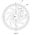
- the bicycle brake rotor 23 basically includes an annular braking ring 23a, a plurality (nine) of outwardly extending connecting arms 23b integrally formed with annular braking ring 23a, and an inner mounting portion 23c integrally formed with the connecting arms 23b. Accordingly, the bicycle brake rotor 23 is a one-piece, unitary member. Preferably, the bicycle brake rotor 23 is constructed of any suitable rigid material.
- the annular braking ring 23a is preferably vented with a plurality of holes.
- the annular braking ring 23a forms an outer braking portion of the bicycle brake rotor 23.
- the outer ends of the connecting arms 23b are equally spaced about the inner edge of the annular braking ring 23a.
- the connecting arms 23b form an intermediate connecting portion of the bicycle brake rotor 23 extending between the annular braking ring 23a and the inner mounting portion 23c. These connecting arms 23b extend tangentially from the inner mounting portion 23c. The connecting arms 23b have triangular openings located therebetween.
- the inner mounting portion 23c has a plurality (six) of axially extending attachment holes 23d.
- the attachment holes 23d have diameters of at least seven millimeters, preferably diameters of eight millimeters.
- the attachment holes 23d are equally spaced about the circumference of the inner mounting portion 23c.
- the inner mounting portion 23c also has a plurality of cutouts 23e, with one of the cutouts 23e located at the base of one of the inner ends of the connecting arms 23b.
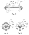
- FIG. 12-17 a pair of alternate bicycle disc brake hubs 112 and 112' are illustrated in accordance with second embodiments of the present invention. These alternate bicycle disc brake hubs 112 and 112' are designed to be used with the bicycle brake rotor 23 illustrated in Figure 11.
- the descriptions of the parts of the second embodiment that are identical to the parts of the first embodiment may be omitted for the sake of brevity.
- the parts of the second embodiment that have the same functions as the parts of the first embodiment will be given the same reference numerals as the parts of the first embodiment, but increased by one hundred.
- the rear disc brake hub 112 basically comprising a hub axle 131, a hub shell 132, a first spoke attachment portion 133 with a plurality of first spoke holes 143, a second spoke attachment portion 134 with a plurality of second spoke holes 144, and a brake rotor attachment portion 135.
- the rear hub 112 is substantially identical to the rear hub 12, except that the rear hub 112 has circularly shaped spoke holes 143 and 144 instead of spoke holes that are notched as in the first embodiment.
- the front disc brake hub 112' basically comprising a hub axle 131', a hub shell 132', a first spoke attachment portion 133' with a plurality of first spoke holes 143', a second spoke attachment portion 134' with a plurality of second spoke holes 144', and a brake rotor attachment portion 135'.
- the front hub 112' is substantially identical to the front hub 12', except that the front hub 112' has circularly shaped spoke holes 143' and 144' instead of spoke holes that are notched as in the first embodiment.
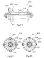
- FIG. 18-23 a pair of alternate bicycle disc brake hubs 212 and 212' are illustrated in accordance with third embodiments of the present invention. These alternate bicycle disc brake hubs 212 and 212' are designed to be used with the bicycle brake rotor 223 illustrated in Figure 24.
- the descriptions of the parts of the third embodiment that are identical to the parts of the first embodiment may be omitted for the sake of brevity.
- the parts of the third embodiment that have the same functions as the parts of the first embodiment will be given the same reference numerals as the parts of the first embodiment, but increased by two hundred.
- the rear disc brake hub 212 basically comprising a hub axle 231, a hub shell 232, a first spoke attachment portion 233 with a plurality of first spoke holes 243, a second spoke attachment portion 234 with a plurality of second spoke holes 244, and a brake rotor attachment portion 235.
- the rear hub 212 is substantially identical to the rear hub 12, except for the configuration of the first spoke attachment portion 233 and the brake rotor attachment portion 235.
- the first spoke attachment portion 233 of the rear hub 212 has sixteen circularly shaped spoke holes 243 and 244 instead of twelve spoke holes that are notched as in the first embodiment.
- the brake rotor attachment portion 235 only has four mounting flanges 251 instead of six mounting flanges 251 as in the first embodiment.
- the front disc brake hub 212' basically comprising a hub axle 231', a hub shell 232', a first spoke attachment portion 233' with a plurality of first spoke holes 243', a second spoke attachment portion 234' with a plurality of second spoke holes 244', and a brake rotor attachment portion 235'.
- the front hub 212' is substantially identical to the front hub 12', except for the configuration of the first spoke attachment portion 233' and the brake rotor attachment portion 235'.
- the first spoke attachment portion 233' of the front hub 212' has sixteen circularly shaped spoke holes 243' and 244' instead of twelve spoke holes that are notched as in the first embodiment.
- the brake rotor attachment portion 235' only has four mounting flanges 251' instead of six mounting flanges 251' as in the first embodiment.
- the bicycle brake rotor 223 basically includes an annular braking ring 223a, a plurality (nine) of outwardly extending connecting arms 223b integrally formed with annular braking ring 223a, and an inner mounting portion 223c integrally formed with the connecting arms 223b.
- the bicycle brake rotor 223 is a one-piece, unitary member.
- the bicycle brake rotor 223 is constructed of any suitable rigid material.
- the bicycle brake rotor 223 is basically identical to the bicycle brake rotor 23, except that the inner mounting portion 223c has four mounting axially extending attachment holes 223d instead of six attachment holes.
- the attachment holes 223d have diameters of at least seven millimeters, preferably diameters of eight millimeters.
- the attachment holes 223d are equally spaced about the circumference of the inner mounting portion 223c.
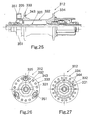
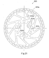
- FIG. 25-30 a pair of alternate bicycle disc brake hubs 312 and 312' are illustrated in accordance with fourth embodiments of the present invention. These alternate bicycle disc brake hubs 312 and 312' are designed to be used with the bicycle brake rotor 323 illustrated in Figure 31.
- the descriptions of the parts of the fourth embodiment that are identical to the parts of the first embodiment may be omitted for the sake of brevity.
- the parts of the fourth embodiment that have the same functions as the parts of the first embodiment will be given the same reference numerals as the parts of the first embodiment, but increased by three hundred.
- the rear disc brake hub 312 basically comprising a hub axle 331, a hub shell 332, a first spoke attachment portion 333 with a plurality of first spoke holes 343, a second spoke attachment portion 334 with a plurality of second spoke holes 344, and a brake rotor attachment portion 335.
- the rear hub 312 is substantially identical to the rear hub 12, except for the configuration of the first spoke attachment portion 333 and the brake rotor attachment portion 335.
- the first spoke attachment portion 333 of the rear hub 312 has eighteen circularly shaped spoke holes 343 and 344 instead of twelve spoke holes that are notched as in the first embodiment.
- the brake rotor attachment portion 335 only has three mounting flanges 351 instead of six mounting flanges 351 as in the first embodiment.
- the front disc brake hub 312' basically comprising a hub axle 331', a hub shell 332', a first spoke attachment portion 333' with a plurality of first spoke holes 343', a second spoke attachment portion 334' with a plurality of second spoke holes 344', and a brake rotor attachment portion 335'.
- the front hub 312' is substantially identical to the front hub 12', except for the configuration of the first spoke attachment portion 333' and the brake rotor attachment portion 335'.
- the first spoke attachment portion 333' of the front hub 312' has eighteen circularly shaped spoke holes 343' and 344' instead of twelve spoke holes that are notched as in the first embodiment.
- the brake rotor attachment portion 335' only has three mounting flanges 351' instead of six mounting flanges 351' as in the first embodiment.
- the bicycle brake rotor 323 basically includes an annular braking ring 323a, a plurality (nine) of outwardly extending connecting arms 323b integrally formed with annular braking ring 323a, and an inner mounting portion 323c integrally formed with the connecting arms 323b.
- the bicycle brake rotor 323 is a one-piece, unitary member.
- the bicycle brake rotor 323 is constructed of any suitable rigid material.
- the bicycle brake rotor 323 is basically identical to the bicycle brake rotor 23, except that the inner mounting portion 323c has three mounting axially extending attachment holes 323d instead of six attachment holes.
- the attachment holes 323d have diameters of at least seven millimeters, preferably diameters of eight millimeters.
- the attachment holes 323d are equally spaced about the circumference of the inner mounting portion 323c.
Landscapes
- Engineering & Computer Science (AREA)
- Mechanical Engineering (AREA)
- General Engineering & Computer Science (AREA)
- Braking Arrangements (AREA)
Applications Claiming Priority (2)
| Application Number | Priority Date | Filing Date | Title |
|---|---|---|---|
| US894875 | 2001-06-29 | ||
| US09/894,875 US6540306B2 (en) | 2001-06-29 | 2001-06-29 | Bicycle disc brake hub |
Publications (3)
| Publication Number | Publication Date |
|---|---|
| EP1270392A2 true EP1270392A2 (fr) | 2003-01-02 |
| EP1270392A3 EP1270392A3 (fr) | 2003-02-05 |
| EP1270392B1 EP1270392B1 (fr) | 2004-10-06 |
Family
ID=25403620
Family Applications (1)
| Application Number | Title | Priority Date | Filing Date |
|---|---|---|---|
| EP02010868A Expired - Lifetime EP1270392B1 (fr) | 2001-06-29 | 2002-05-15 | Moyeu de bicyclette pour disque de frein |
Country Status (7)
| Country | Link |
|---|---|
| US (1) | US6540306B2 (fr) |
| EP (1) | EP1270392B1 (fr) |
| JP (1) | JP3703781B2 (fr) |
| CN (1) | CN1247407C (fr) |
| CZ (1) | CZ20021930A3 (fr) |
| DE (1) | DE60201470T2 (fr) |
| TW (1) | TWI241262B (fr) |
Cited By (5)
| Publication number | Priority date | Publication date | Assignee | Title |
|---|---|---|---|---|
| EP1695842A2 (fr) | 2005-02-28 | 2006-08-30 | Shimano Inc. | Moyeu de bicyclette |
| US7413350B2 (en) * | 2004-02-20 | 2008-08-19 | Shimano Inc. | Bicycle hub |
| EP1894743A3 (fr) * | 2006-08-31 | 2009-04-29 | DT Swiss AG | Moyeu et roue de roulement, en particulier pour vélos |
| EP2078620A1 (fr) * | 2008-01-11 | 2009-07-15 | Chosen Co., Ltd. | Moyeu, particulièrement un moyeu arrière pour bicyclette |
| CN103133574A (zh) * | 2011-11-24 | 2013-06-05 | 株式会社岛野 | 自行车盘式制动器转子 |
Families Citing this family (16)
| Publication number | Priority date | Publication date | Assignee | Title |
|---|---|---|---|---|
| JP3732182B2 (ja) * | 2003-01-09 | 2006-01-05 | 株式会社シマノ | 自転車用ハブ |
| US6854569B2 (en) * | 2003-03-18 | 2005-02-15 | Kun Teng Industry Co., Ltd. | Brakable wheel hub device |
| JP2005030565A (ja) * | 2003-07-11 | 2005-02-03 | Shimano Inc | 自転車用ディスクロータ |
| US7140626B1 (en) | 2003-07-15 | 2006-11-28 | Keay Peter W | Running exercise bike |
| JP2005188704A (ja) * | 2003-12-26 | 2005-07-14 | Shimano Inc | ディスクブレーキロータアセンブリ |
| JP2005308059A (ja) * | 2004-04-20 | 2005-11-04 | Shimano Inc | 自転車用ディスクブレーキロータ組立体 |
| US20060219488A1 (en) * | 2005-03-29 | 2006-10-05 | Chun-Hsung Chen | Disc brake hub adapter structure |
| US20060284472A1 (en) * | 2005-06-16 | 2006-12-21 | Kun Teng Industry Co., Ltd. | Brakable wheel hub device |
| US7665584B2 (en) * | 2006-04-17 | 2010-02-23 | Shimano Inc. | Disc rotor retaining assembly |
| JP2007290606A (ja) * | 2006-04-26 | 2007-11-08 | Shimano Inc | 自転車用ハブ |
| JP2011201398A (ja) * | 2010-03-25 | 2011-10-13 | Honda Motor Co Ltd | 自動二輪車のホイール |
| DE202013011069U1 (de) | 2013-12-06 | 2014-01-17 | Dirk Klein | Sicherheitseinrichtung für eine Bremsscheibe eines Fahrrads und eine Scheibenbremse für ein Fahrrad |
| IT201700091932A1 (it) * | 2017-08-08 | 2019-02-08 | Campagnolo Srl | Mozzo di ruota per bicicletta e correlato assieme di mozzo |
| US10837509B2 (en) | 2018-07-20 | 2020-11-17 | Bendix Spicer Foundation Brake Llc | Brake disc mounting arrangement |
| US10704628B2 (en) | 2018-07-20 | 2020-07-07 | Bendix Spicer Foundation Brake Llc | Brake disc mounting arrangement |
| US10830295B2 (en) | 2018-07-20 | 2020-11-10 | Bendix Spicer Foundation Brake Llc | Brake disc mounting arrangement |
Family Cites Families (21)
| Publication number | Priority date | Publication date | Assignee | Title |
|---|---|---|---|---|
| US1975221A (en) * | 1929-07-15 | 1934-10-02 | Kelsey Hayes Wheel Corp | Wheel |
| US4170369A (en) * | 1978-01-23 | 1979-10-09 | Lauren Strutman | Bicycle wheel suspension, driving and braking assembly |
| US4634189A (en) * | 1982-06-28 | 1987-01-06 | Hamelin Industries, Inc. | Wheel hub including structure for attachment of accessories |
| US6428113B2 (en) * | 1991-12-24 | 2002-08-06 | Rolf Dietrich | Cycle and tensioned spoked wheel assembly |
| US5487592A (en) * | 1992-03-02 | 1996-01-30 | Rasmussen; Clark W. | Hub for bicycle wheels |
| US5489147A (en) * | 1993-12-30 | 1996-02-06 | Borsai; Laszlo G. | Hub for spoked wheel axle |
| US5626401A (en) * | 1994-05-17 | 1997-05-06 | Innovative Bicycle Components Company | Spoked wheel hub |
| US5647643A (en) * | 1995-03-01 | 1997-07-15 | Noble; Ryun Bates | Wheel hub |
| US5795036A (en) * | 1995-05-26 | 1998-08-18 | Campagnolo S.R.L. | Bicycle rear wheel |
| US6145938A (en) * | 1996-10-11 | 2000-11-14 | Dietrich; Rolf | Cycle, tensioned spoked wheel assembly and hub therefor |
| DE19724327B4 (de) * | 1997-06-10 | 2009-01-29 | Sram Deutschland Gmbh | Nabe für ein Speichenrad |
| US5950772A (en) | 1997-08-29 | 1999-09-14 | Hayes Brake, Inc. | Bicycle brake system having a flexible disk |
| US6244667B1 (en) * | 1998-08-25 | 2001-06-12 | Rolf Dietrich | Tensioned spoked bicycle wheel assembly and hub therefor |
| DE19915714A1 (de) | 1999-04-08 | 2000-10-12 | Sram De Gmbh | Nabe für Fahrräder |
| FR2794063B1 (fr) * | 1999-05-28 | 2001-07-27 | Mavic Sa | Moyeu de roue de bicyclette prevu pour etre equipe d'un disque de freinage |
| DE19926641C5 (de) | 1999-06-11 | 2010-04-08 | Sram Deutschland Gmbh | Nabe für ein Laufrad |
| US6354669B1 (en) * | 2000-01-31 | 2002-03-12 | Shimano Inc. | Bicycle hub for tangential spokes |
| US6352314B1 (en) * | 2000-01-31 | 2002-03-05 | Shimano Inc. | Bicycle hub for disc brake |
| US6318810B1 (en) * | 2000-03-06 | 2001-11-20 | Frank T. Miyake | Motorcycle modular carrier ring |
| US6336531B1 (en) * | 2000-03-15 | 2002-01-08 | Tzu-Chieh Chou | Braking disc assembly |
| US6431658B1 (en) * | 2000-03-17 | 2002-08-13 | Shimano Inc. | Bicycle hub |
-
2001
- 2001-06-29 US US09/894,875 patent/US6540306B2/en not_active Expired - Lifetime
-
2002
- 2002-04-22 TW TW091108237A patent/TWI241262B/zh not_active IP Right Cessation
- 2002-05-15 EP EP02010868A patent/EP1270392B1/fr not_active Expired - Lifetime
- 2002-05-15 DE DE60201470T patent/DE60201470T2/de not_active Expired - Lifetime
- 2002-05-23 CN CN02120329.6A patent/CN1247407C/zh not_active Expired - Fee Related
- 2002-06-04 CZ CZ20021930A patent/CZ20021930A3/cs unknown
- 2002-06-18 JP JP2002177313A patent/JP3703781B2/ja not_active Expired - Fee Related
Cited By (7)
| Publication number | Priority date | Publication date | Assignee | Title |
|---|---|---|---|---|
| US7413350B2 (en) * | 2004-02-20 | 2008-08-19 | Shimano Inc. | Bicycle hub |
| EP1695842A2 (fr) | 2005-02-28 | 2006-08-30 | Shimano Inc. | Moyeu de bicyclette |
| EP1695842A3 (fr) * | 2005-02-28 | 2007-09-12 | Shimano Inc. | Moyeu de bicyclette |
| EP1894743A3 (fr) * | 2006-08-31 | 2009-04-29 | DT Swiss AG | Moyeu et roue de roulement, en particulier pour vélos |
| EP2078620A1 (fr) * | 2008-01-11 | 2009-07-15 | Chosen Co., Ltd. | Moyeu, particulièrement un moyeu arrière pour bicyclette |
| CN103133574A (zh) * | 2011-11-24 | 2013-06-05 | 株式会社岛野 | 自行车盘式制动器转子 |
| CN103133574B (zh) * | 2011-11-24 | 2016-04-13 | 株式会社岛野 | 自行车盘式制动器转子 |
Also Published As
| Publication number | Publication date |
|---|---|
| CZ20021930A3 (cs) | 2003-08-13 |
| TWI241262B (en) | 2005-10-11 |
| EP1270392A3 (fr) | 2003-02-05 |
| JP2003063203A (ja) | 2003-03-05 |
| EP1270392B1 (fr) | 2004-10-06 |
| CN1393367A (zh) | 2003-01-29 |
| US6540306B2 (en) | 2003-04-01 |
| US20030000779A1 (en) | 2003-01-02 |
| JP3703781B2 (ja) | 2005-10-05 |
| DE60201470T2 (de) | 2006-03-09 |
| CN1247407C (zh) | 2006-03-29 |
| DE60201470D1 (de) | 2004-11-11 |
Similar Documents
| Publication | Publication Date | Title |
|---|---|---|
| EP1270392B1 (fr) | Moyeu de bicyclette pour disque de frein | |
| US6371252B1 (en) | Bicycle disc brake hub | |
| JP3545373B2 (ja) | 自転車用ハブアッセンブリ | |
| EP1213217B1 (fr) | Moyeu de bicyclette | |
| US6669306B1 (en) | Bicycle hub axle assembly | |
| US7066556B2 (en) | Bicycle hub | |
| US6409282B1 (en) | Bicycle hub | |
| US6886894B2 (en) | Bicycle hub axle | |
| US6352314B1 (en) | Bicycle hub for disc brake | |
| US6309028B1 (en) | Bicycle hub | |
| US6354669B1 (en) | Bicycle hub for tangential spokes | |
| US6485108B1 (en) | Bicycle hub | |
| US7374251B2 (en) | Connection of Spokes to hub and rim in bicycle wheel | |
| US6511133B1 (en) | Bicycle hub with spoke seal |
Legal Events
| Date | Code | Title | Description |
|---|---|---|---|
| PUAI | Public reference made under article 153(3) epc to a published international application that has entered the european phase |
Free format text: ORIGINAL CODE: 0009012 |
|
| PUAL | Search report despatched |
Free format text: ORIGINAL CODE: 0009013 |
|
| AK | Designated contracting states |
Kind code of ref document: A2 Designated state(s): AT BE CH CY DE DK ES FI FR GB GR IE IT LI LU MC NL PT SE TR |
|
| AX | Request for extension of the european patent |
Free format text: AL;LT;LV;MK;RO;SI |
|
| AK | Designated contracting states |
Designated state(s): AT BE CH CY DE DK ES FI FR GB GR IE IT LI LU MC NL PT SE TR |
|
| AX | Request for extension of the european patent |
Extension state: AL LT LV MK RO SI |
|
| 17P | Request for examination filed |
Effective date: 20030218 |
|
| 17Q | First examination report despatched |
Effective date: 20030506 |
|
| AKX | Designation fees paid |
Designated state(s): DE FR GB IE IT NL |
|
| GRAP | Despatch of communication of intention to grant a patent |
Free format text: ORIGINAL CODE: EPIDOSNIGR1 |
|
| GRAS | Grant fee paid |
Free format text: ORIGINAL CODE: EPIDOSNIGR3 |
|
| GRAA | (expected) grant |
Free format text: ORIGINAL CODE: 0009210 |
|
| AK | Designated contracting states |
Kind code of ref document: B1 Designated state(s): DE FR GB IE IT NL |
|
| REG | Reference to a national code |
Ref country code: GB Ref legal event code: FG4D |
|
| REG | Reference to a national code |
Ref country code: IE Ref legal event code: FG4D |
|
| REF | Corresponds to: |
Ref document number: 60201470 Country of ref document: DE Date of ref document: 20041111 Kind code of ref document: P |
|
| PGFP | Annual fee paid to national office [announced via postgrant information from national office to epo] |
Ref country code: IE Payment date: 20050524 Year of fee payment: 4 |
|
| PLBE | No opposition filed within time limit |
Free format text: ORIGINAL CODE: 0009261 |
|
| STAA | Information on the status of an ep patent application or granted ep patent |
Free format text: STATUS: NO OPPOSITION FILED WITHIN TIME LIMIT |
|
| 26N | No opposition filed |
Effective date: 20050707 |
|
| ET | Fr: translation filed | ||
| PG25 | Lapsed in a contracting state [announced via postgrant information from national office to epo] |
Ref country code: GB Free format text: LAPSE BECAUSE OF NON-PAYMENT OF DUE FEES Effective date: 20060515 Ref country code: IE Free format text: LAPSE BECAUSE OF NON-PAYMENT OF DUE FEES Effective date: 20060515 |
|
| GBPC | Gb: european patent ceased through non-payment of renewal fee |
Effective date: 20060515 |
|
| REG | Reference to a national code |
Ref country code: IE Ref legal event code: MM4A |
|
| PGFP | Annual fee paid to national office [announced via postgrant information from national office to epo] |
Ref country code: NL Payment date: 20080501 Year of fee payment: 7 |
|
| NLV4 | Nl: lapsed or anulled due to non-payment of the annual fee |
Effective date: 20091201 |
|
| PG25 | Lapsed in a contracting state [announced via postgrant information from national office to epo] |
Ref country code: NL Free format text: LAPSE BECAUSE OF NON-PAYMENT OF DUE FEES Effective date: 20091201 |
|
| REG | Reference to a national code |
Ref country code: FR Ref legal event code: ST Effective date: 20100129 |
|
| PG25 | Lapsed in a contracting state [announced via postgrant information from national office to epo] |
Ref country code: FR Free format text: LAPSE BECAUSE OF NON-PAYMENT OF DUE FEES Effective date: 20090602 |
|
| PGFP | Annual fee paid to national office [announced via postgrant information from national office to epo] |
Ref country code: FR Payment date: 20080514 Year of fee payment: 7 |
|
| PGFP | Annual fee paid to national office [announced via postgrant information from national office to epo] |
Ref country code: IT Payment date: 20140520 Year of fee payment: 13 |
|
| PG25 | Lapsed in a contracting state [announced via postgrant information from national office to epo] |
Ref country code: IT Free format text: LAPSE BECAUSE OF NON-PAYMENT OF DUE FEES Effective date: 20150515 |
|
| PGFP | Annual fee paid to national office [announced via postgrant information from national office to epo] |
Ref country code: DE Payment date: 20170509 Year of fee payment: 16 |
|
| REG | Reference to a national code |
Ref country code: DE Ref legal event code: R119 Ref document number: 60201470 Country of ref document: DE |
|
| PG25 | Lapsed in a contracting state [announced via postgrant information from national office to epo] |
Ref country code: DE Free format text: LAPSE BECAUSE OF NON-PAYMENT OF DUE FEES Effective date: 20181201 |