EP1270400A2 - Dispositif de mât avec une unité flottante pour un sous-marin - Google Patents
Dispositif de mât avec une unité flottante pour un sous-marin Download PDFInfo
- Publication number
- EP1270400A2 EP1270400A2 EP02009925A EP02009925A EP1270400A2 EP 1270400 A2 EP1270400 A2 EP 1270400A2 EP 02009925 A EP02009925 A EP 02009925A EP 02009925 A EP02009925 A EP 02009925A EP 1270400 A2 EP1270400 A2 EP 1270400A2
- Authority
- EP
- European Patent Office
- Prior art keywords
- mast
- unit
- submarine
- coupling means
- mast device
- Prior art date
- Legal status (The legal status is an assumption and is not a legal conclusion. Google has not performed a legal analysis and makes no representation as to the accuracy of the status listed.)
- Granted
Links
- 230000008878 coupling Effects 0.000 claims abstract description 28
- 238000010168 coupling process Methods 0.000 claims abstract description 28
- 238000005859 coupling reaction Methods 0.000 claims abstract description 28
- 229920000049 Carbon (fiber) Polymers 0.000 claims abstract description 4
- 239000004917 carbon fiber Substances 0.000 claims abstract description 4
- VNWKTOKETHGBQD-UHFFFAOYSA-N methane Chemical compound C VNWKTOKETHGBQD-UHFFFAOYSA-N 0.000 claims abstract description 4
- 238000007667 floating Methods 0.000 claims description 18
- 230000015572 biosynthetic process Effects 0.000 claims description 2
- 230000008054 signal transmission Effects 0.000 claims description 2
- 239000007787 solid Substances 0.000 claims description 2
- 230000009182 swimming Effects 0.000 claims description 2
- 230000000087 stabilizing effect Effects 0.000 claims 1
- 230000009189 diving Effects 0.000 abstract 1
- XLYOFNOQVPJJNP-UHFFFAOYSA-N water Substances O XLYOFNOQVPJJNP-UHFFFAOYSA-N 0.000 description 17
- 239000007822 coupling agent Substances 0.000 description 3
- 238000000034 method Methods 0.000 description 3
- 230000033001 locomotion Effects 0.000 description 2
- 238000004519 manufacturing process Methods 0.000 description 2
- 230000003287 optical effect Effects 0.000 description 2
- 230000002411 adverse Effects 0.000 description 1
- 230000005540 biological transmission Effects 0.000 description 1
- 238000004891 communication Methods 0.000 description 1
- 239000002131 composite material Substances 0.000 description 1
- 238000010276 construction Methods 0.000 description 1
- 230000003247 decreasing effect Effects 0.000 description 1
- 230000002996 emotional effect Effects 0.000 description 1
- 239000000835 fiber Substances 0.000 description 1
- 239000006260 foam Substances 0.000 description 1
- 238000009434 installation Methods 0.000 description 1
- 239000000463 material Substances 0.000 description 1
- 239000003381 stabilizer Substances 0.000 description 1
Images


Classifications
-
- H—ELECTRICITY
- H01—ELECTRIC ELEMENTS
- H01Q—ANTENNAS, i.e. RADIO AERIALS
- H01Q1/00—Details of, or arrangements associated with, antennas
- H01Q1/27—Adaptation for use in or on movable bodies
- H01Q1/34—Adaptation for use in or on ships, submarines, buoys or torpedoes
-
- B—PERFORMING OPERATIONS; TRANSPORTING
- B63—SHIPS OR OTHER WATERBORNE VESSELS; RELATED EQUIPMENT
- B63G—OFFENSIVE OR DEFENSIVE ARRANGEMENTS ON VESSELS; MINE-LAYING; MINE-SWEEPING; SUBMARINES; AIRCRAFT CARRIERS
- B63G8/00—Underwater vessels, e.g. submarines; Equipment specially adapted therefor
- B63G8/38—Arrangement of visual or electronic watch equipment, e.g. of periscopes, of radar
-
- H—ELECTRICITY
- H01—ELECTRIC ELEMENTS
- H01Q—ANTENNAS, i.e. RADIO AERIALS
- H01Q1/00—Details of, or arrangements associated with, antennas
- H01Q1/12—Supports; Mounting means
-
- B—PERFORMING OPERATIONS; TRANSPORTING
- B63—SHIPS OR OTHER WATERBORNE VESSELS; RELATED EQUIPMENT
- B63B—SHIPS OR OTHER WATERBORNE VESSELS; EQUIPMENT FOR SHIPPING
- B63B22/00—Buoys
- B63B22/18—Buoys having means to control attitude or position, e.g. reaction surfaces or tether
-
- B—PERFORMING OPERATIONS; TRANSPORTING
- B63—SHIPS OR OTHER WATERBORNE VESSELS; RELATED EQUIPMENT
- B63B—SHIPS OR OTHER WATERBORNE VESSELS; EQUIPMENT FOR SHIPPING
- B63B2203/00—Communication means
Definitions
- the invention is based on a mast device for a submarine according to the preamble of claim 1.
- Such a known mast device for submarines consists in that at the top of the mast that is vertical in a guide device is movable, information means that are connected to the control center inside the Submarines are in electrical communication, for transmission and receiving information are provided.
- the Information means are firmly connected to the top of the mast and can be extended a certain distance, so that they stick out of the mast. Shall information be sent and / or received, the submarine moves to observation depth, which corresponds to the height of the extended mast, so that the information resources are above the water surface.
- a buoyant unit in the form of a buoy to provide which has an optical observation device.
- This Buoy is detachably attached to the hull of the submarine, remains with him on a rope, which also provides information signals Command post directs when connected to the buoy from the submarine has been replaced and due to their own buoyancy on the water surface has arrived.
- the submarine is equipped with a winch to the Being able to retract the buoy after it has ended.
- the provision an information buoy allows the submarine to face Submarines with information masts carrying masts can take a deeper observation dive position to make observations to be able to make above the water surface.
- adversely with these known buoy constructions is that the main body of the submarine for the installation or inclusion of the Floatable buoy is also specially designed, what with appropriate Manufacturing costs and a large space requirement is.
- the object of the invention is to introduce a mast device to continue training in such a way that they are in comparison to their extended state a greater observation depth of the submarine for the exchange of information above the water surface allowed.
- the design of the mast device according to the invention makes it possible to that the submarine also has one, i.e. H. deeper observation depth can take, which is larger than that which the bare extension distance of the mast device corresponds.
- Another advantage consists of a separate floating information unit in addition to the mast device, which gives the further advantage results in no special room or space on or in the submarine must be provided for a floating information unit and thus also the manufacturing costs for a separate information unit and the formation of a space for their positioning in the fed Condition not applicable.
- Another advantage of the invention Fattening device is that its information unit is also conventional Way for sending and / or receiving information can be used above the water surface, d. H. that the Mast is extended around its usual extension, the buoyant Unity with the information resources, however, on the top of the mast remains.
- the floatable unit with the help of a seat training in the upper Mast area and with the help of the coupling means positionally secure in the Area of the top of the mast.
- the mast device relieved a removable mast wall part Release and reposition the floatable unit from or has at the top of the mast.
- the mast wall part is preferably laterally designed to be pivotable, e.g. B. with the help of a piston-cylinder unit.
- the coupling means consists of which connects the floatable unit with the mast, from one Rope, e.g. B. a wire rope or a carbon fiber rope.
- the coupling agent can also use, for example, electrical signal lines for signal transmission contain.
- the coupling means is by means of a Winch let out of the mast and retracted.
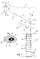
- 1 comprises the mast device, generally designated 1 a mast 2 which can be moved vertically in a conventional manner, a guide device 3 for the mast, a buoyant unit 4 with conventional Information means 5 for sending and / or receiving of information of all kinds above the water surface, a flexible Coupling means 7, preferably in the form of a wire rope or Carbon fiber rope, with which signal lines for electrical signals to and can be combined by the information means 5, as well as a winch 8 for releasing and retracting the coupling agent to the floatable unit 4 to rise to the water surface 6 or move in from there.
- the winch 8 can be outside the guide device 3, e.g. B. provided next to her, or in the mast (Fig. 9) his. According to FIG.
- the mast 2 has a streamlined cross-sectional profile and is by means of a piston-cylinder unit (not shown) in conventionally vertically movable so that it from the tower 9 of the Submarines, the upper edge of which is indicated with 9a can be.
- the guide device 3 is, for example, in the form of a Shaft trained, the z. B in a known manner from fiber composite material will be produced.
- the shaft-shaped guide device 3 can be reinforced with ribs 3a.
- the guide device 3, the alternative can also be designed in the form of columns, extends essentially to the upper edge 9a of the tower 9.
- the mast 2 is completely in the shaft-shaped guide device 3 retractable so that it in this State also does not protrude above the upper edge 9a of the tower 9.
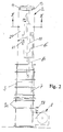
- the floatable unit 4 which is not fixed to the top of the mast connected, comprises an elongated, vertical in the floating state Floating bodies standing in the water, causing a buoyancy 10, which has a platform 11 at its upper end, which when retracted Unit 4 sits on the top of mast 2 and this Top closes.
- the information means 5, for example radar means, Radio means and / or optical devices are known in housed a housing 12 which is in the operating position Unit 4 is located above the platform 11.
- the housing 12 penetrates the platform 11 is approximately in the middle and is connected to the floating body 10 firmly connected.
- the float 10 is the Unit 4 is preferably detachably connected to the platform 11.
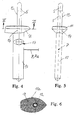
- the platform 11 thus has a passage 14 through which the housing 12 with the information means 5 through emotional.
- the vertical movement of the float 10 with the housing 12 of the Floatable unit 4 within the mast 2 is carried out by means of a Receiving device 15, which receives the buoyancy body 10 and detected, the receiving device 15 by means of a piston-cylinder unit 16 is vertically movable.
- the floating body 10 aerodynamically designed in cross-section to ensure a quiet swimming position to reach unit 4.
- the coupling means 7 takes up approximately half the height of the float 10 on this.
- the circumferential course 11a of the platform 11 is adapted to the flow profile of the mast 2 (Fig. 3).
- a seat design is provided in the area of the upper end of the mast 2, which in addition to the seat 13 comprises two further seats 18 and 19, to position the floatable unit 4 securely in the mast, when it is retracted. In this state it is made flexible by means of the Coupling means 7 and the seats 13, 18 and 19 secure position held.
- a mast wall part 20 is removable at the top of the mast and designed to be resettable again, preferably laterally pivotable, as clearly shown in Fig. 1.
- the lateral pivoting of the mast wall part 20 can be done by means of a piston-cylinder unit 21.
- the length of the pivotable mast wall part corresponds advantageously the height of the float 10 of the floatable unit 4.
- Im Cross section includes the mast wall part 20 about half the circumference of the Mast top end, as Fig. 3 clearly shows.
- a deflection roller 22 for the flexible Coupling means 7 are provided in the area of the remaining Fixed part 2a of the top of the mast. It is understandable that if that Coupling means 7 is released, the unit 4 slightly different from the Can remove seats 18 and 13 and thus from the top of the mast, if the mast wall part 20 is pivoted away. Conversely, the unit can be without Difficulty positioned again at the end of the mast on the seats 13, 18, 19 when the coupling means 7 is drawn in.
- the floatable Unit 4 which with the usual information means 5 for sending and / or receiving information, connection-free on The top of the mast is held when it is retracted located. It is only for the unit 4 to rise to the water surface 6 required to pivot the mast wall part 20 and that To release coupling means 7. Because of their own buoyancy the floatable unit 4 then moves up to the water surface 6. According to the desired observation depth for the submarine, the coupling means 7 from the Mast 2 let out.
- the mast device 2 can be provided with a capping device 23 be able to cut the coupling means 7 in an emergency.
- other positions also come in the mast device 1 in question.
- FIG. 7 shows the pulling-in process for the floatable unit 4.
- Fig. 7 A is the unit 4 on the water surface 6.
- the winch 8 becomes the rope-shaped coupling means 7 and thus the unit 4 retracted (Fig. 7 B).
- the coupling agent has been drawn in the mast wall part 20 is attached to the fixed mast top end 2a pivoted so that the unit 4 is in the correct position and connection-free sits on the top of the mast (Fig. 7 C).
- the housing 12 with the information means 5 floating bodies 10 further drawn in with the aid of the receiving device 15, such that the housing 12 no longer protrudes from the platform 11 (FIG. 7 D).
- the mast 2 is hydraulically into the shaft-shaped guide device 3 retracted so that the mast is no longer out of the tower 9 of the submarine protrudes, as can clearly be seen from FIG. 7E.
- the floatable unit 4 reach the water surface 6 is done in reverse order.
- the Unit 4 adjacent section 7a of flexible coupling means 7 provided with at least one buoyancy means 23.
- This buoyant can be made from a hollow body or from a solid body from a buoyant Material, e.g. B. foam exist.
- one of the float 10 of the unit 4 has a certain distance, as shown in FIG. 8, can also be done in this way that the section 7a with a plurality of cylindrical or spherical buoyancy bodies is provided, which are perforated centrally and are lined up on section 7a.
- a rod-shaped buoyancy body with a central through hole section 7a can be retracted.
- the buoyancy of each buoyancy body 23 is set so that section 7a of the coupling means 7 sets substantially horizontally when the submarine is in Drive is located, so that the floating unit 4 has a stabilized vertical position occupies.
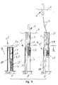
- FIG. 9 A second embodiment of the mast device according to the invention is shown in Fig. 9 and generally designated 25.
- This embodiment is simplified compared to embodiment 1.
- the floatable unit 4 has a cylindrical shape overall on, whose lower region is designed as a float 26, while the upper part of which is designed as a waterproof housing 27, in which the aforementioned information means 5 are included.
- a winch 28 is provided in the mast 2, on which the flexible Coupling means 7 is wound.
- a capping device 29 is provided, which is arranged in the mast 2 is.
- the mast 2 is in the usual way by means of a piston-cylinder unit 29 vertically movable in the shaft-shaped guide device 3, such that the mast 2 to its upper end position outside the Tower 9 of the submarine can be driven.
- the mast 2 is in the area of its upper end with a tubular receptacle 30 designed for the cylindrical, floatable unit 4.
- Fig. 9 is an extension process for the floatable unit 4 of the mast device 25 shown.
- 9A shows the mast device 25 inclusive their buoyant unit 4 in fully retracted Status.
- the mast 2 and / or the floating unit 4 are standing compared to the upper edge 9a of the tower 9 not upwards.
- Fig. 9 B shows the mast 2 in the extended state, such that the The top of the mast protrudes slightly from the water surface 6.
- the buoyant unit 4 is partially extended in such a way that it is still in with its lower end the mast 2 is located. Even in this operating position of the unit 4 can Information is sent and received.
- the observation depth of the submarine is essential in this case determined by the extended mast 2.
- FIG. 9C shows the case that the submarine in a compared to the case of Fig. 9 B essential deeper observation depth. In this case it is Coupling means 7 further unwound from the winch 28 and protrudes the top of the mast 2 by the desired length, whereby the unit floats on the water surface 6 in vertical position.
- 9B and 9C it is clear that the one described above Mast device both in the conventional operating position (Fig. 9 B) and in an operating position with a considerably greater depth of observation of the submarine (Fig. 9 C) can be used. Both apply also for the embodiment 1 according to FIGS. 1 to 8.
- the coupling means 7 a total length that is essentially the maximum desired Observation depth of the submarine corresponds.
Landscapes
- Engineering & Computer Science (AREA)
- Radar, Positioning & Navigation (AREA)
- Mechanical Engineering (AREA)
- Aviation & Aerospace Engineering (AREA)
- Testing Or Calibration Of Command Recording Devices (AREA)
- Electric Cable Installation (AREA)
- Arrangements For Transmission Of Measured Signals (AREA)
- Laying Of Electric Cables Or Lines Outside (AREA)
Applications Claiming Priority (2)
| Application Number | Priority Date | Filing Date | Title |
|---|---|---|---|
| DE10129696A DE10129696A1 (de) | 2001-06-22 | 2001-06-22 | Mastvorrichtung für ein Unterseeboot |
| DE10129696 | 2001-06-22 |
Publications (3)
| Publication Number | Publication Date |
|---|---|
| EP1270400A2 true EP1270400A2 (fr) | 2003-01-02 |
| EP1270400A3 EP1270400A3 (fr) | 2003-06-04 |
| EP1270400B1 EP1270400B1 (fr) | 2004-11-03 |
Family
ID=7688804
Family Applications (1)
| Application Number | Title | Priority Date | Filing Date |
|---|---|---|---|
| EP02009925A Expired - Lifetime EP1270400B1 (fr) | 2001-06-22 | 2002-05-03 | Dispositif de mât avec une unité flottante pour un sous-marin |
Country Status (3)
| Country | Link |
|---|---|
| US (2) | US6907839B2 (fr) |
| EP (1) | EP1270400B1 (fr) |
| DE (2) | DE10129696A1 (fr) |
Cited By (6)
| Publication number | Priority date | Publication date | Assignee | Title |
|---|---|---|---|---|
| DE102005012900B3 (de) * | 2005-03-21 | 2006-04-20 | Grundmann, Klaus | Verfahren und Vorrichtung zur von einer Unterwassereinheit aus geführten visuellen und elektronischen Beobachtung |
| EP1897800A1 (fr) | 2006-08-30 | 2008-03-12 | Howaldtswerke-Deutsche Werft GmbH | Dispositif pour lever, maintenir et/ou charger une balise de communication dirigée par câble |
| WO2010144625A1 (fr) | 2009-06-12 | 2010-12-16 | Race Roger E | Système et procédé d'antenne remorquée |
| WO2011003379A1 (fr) * | 2009-07-08 | 2011-01-13 | Gabler Maschinenbau Gmbh | Dispositif dintroduction et de retrait dun corps remorqué relié par un câble permettant d'introduire le corps dans un sous-marin à létat immergé et de le retirer de ce sous-marin |
| EP1935779A3 (fr) * | 2006-12-22 | 2014-06-04 | ThyssenKrupp Marine Systems GmbH | Submersible |
| EP2792593A1 (fr) * | 2013-04-18 | 2014-10-22 | Dcns | Ensemble perfectionné d'un mât télescopique et d'un dispositif de support d'un équipement, pour un véhicule sous-marin |
Families Citing this family (22)
| Publication number | Priority date | Publication date | Assignee | Title |
|---|---|---|---|---|
| DE10337479A1 (de) * | 2003-08-14 | 2005-03-10 | Gabler Gmbh Maschbau | Kolbenstange, Zylindereinheit mit einer solchen Kolbenstange und Verfahren zu deren Herstellung |
| US6845728B1 (en) * | 2003-10-06 | 2005-01-25 | The United States Of America As Represented By The Secretary Of The Navy | Towable submarine mast simulator |
| US7165504B1 (en) * | 2004-12-20 | 2007-01-23 | The United States Of America As Represented By The Secretary Of The Navy. | Antenna linear extension and retraction apparatus for a submersible device, and method of use |
| US8383959B2 (en) * | 2005-04-18 | 2013-02-26 | Stephen Burns Kessler | Metamaterial spheric alignment mechanism |
| US20100227552A1 (en) * | 2005-06-15 | 2010-09-09 | Mark Volanthen | Underwater radio antenna |
| US20100227551A1 (en) * | 2005-06-15 | 2010-09-09 | Mark Volanthen | Buoy supported underwater radio antenna |
| US7512036B2 (en) | 2005-08-16 | 2009-03-31 | Ocean Server Technology, Inc. | Underwater acoustic positioning system and method |
| DE102005059825A1 (de) * | 2005-12-14 | 2007-02-01 | Carl Zeiss Optronics Gmbh | Mastvorrichtung für ein Unterseeboot |
| EP1989569A2 (fr) * | 2006-02-23 | 2008-11-12 | Ocean Server Technology, Inc. | Système et procédé de détermination de la position d'un véhicule sous-marin |
| US7429957B1 (en) * | 2007-02-20 | 2008-09-30 | The United States Of America As Represented By The Secretary Of The Navy | Wideband floating wire antenna using a double negative meta-material |
| US7559288B2 (en) * | 2007-07-30 | 2009-07-14 | The United States Of America As Represented By The Secretary Of The Navy | Recoverable optical fiber tethered buoy assembly |
| GB0803834D0 (en) * | 2008-02-29 | 2008-04-09 | Strachan & Henshaw Ltd | Buoy |
| DE102010010601B4 (de) | 2010-03-08 | 2012-03-15 | Howaldtswerke-Deutsche Werft Gmbh | Bojenschleppantenne |
| DE102011009283A1 (de) * | 2011-01-24 | 2012-07-26 | Gabler Maschinenbau Gmbh | Antenne für ein Unterseeboot |
| US8601970B1 (en) * | 2011-06-13 | 2013-12-10 | The United States Of America As Represented By The Secretary Of The Navy | Tethered buoy housing and deployment assembly |
| FR2977232B1 (fr) * | 2011-07-01 | 2014-10-17 | Dcns | Structure perfectionnee de support et de guidage de mat hissable de vehicule sous-marin |
| ITBO20120200A1 (it) * | 2012-04-13 | 2013-10-14 | Calzoni Srl | Apparato di sollevamento per dispositivi di interfaccia con l'ambiente esterno in un sommergibile e sommergibile comprendente detto apparato |
| DE102012209082A1 (de) * | 2012-05-30 | 2013-12-05 | Gabler Maschinenbau Gmbh | Ausfahrgerät für ein Unterseeboot |
| JP6108445B2 (ja) * | 2013-03-13 | 2017-04-05 | 戸田建設株式会社 | 浮体式洋上風力発電設備 |
| FR3016338A1 (fr) * | 2014-01-14 | 2015-07-17 | Bmti | Dispositif de deploiement d'un long cable de communication pour bouee larguee depuis un sas de sous-marin |
| US10656267B2 (en) | 2015-09-08 | 2020-05-19 | Oceanserver Technology, Inc. | Underwater acoustic tracking and two way messaging system |
| US11539119B1 (en) * | 2019-07-02 | 2022-12-27 | Hrl Laboratories, Llc | Slanted top loaded monopole for VLF generation |
Citations (2)
| Publication number | Priority date | Publication date | Assignee | Title |
|---|---|---|---|---|
| DE758461C (de) | 1942-06-27 | 1945-01-11 | Carl Sandvoss | Beobachtungseinrichtung fuer Unterseeboote |
| DE2837134A1 (de) | 1978-08-25 | 1980-03-06 | Licentia Gmbh | Anordnung fuer unterwasserfahrzeuge zur erkennung, identifizierung und sichtbarmachung von ueberwasserfahrzeugen und/oder flugkoerpern |
Family Cites Families (19)
| Publication number | Priority date | Publication date | Assignee | Title |
|---|---|---|---|---|
| US1746547A (en) * | 1928-02-11 | 1930-02-11 | John L Mckay | Rescue appliance for submarines |
| US2273497A (en) * | 1940-02-03 | 1942-02-17 | Rivera Benito | Signal pontoon for submarines |
| US3034471A (en) * | 1959-08-25 | 1962-05-15 | Vare Ind | Method of nesting an underwater towed vehicle |
| US3788255A (en) * | 1960-04-26 | 1974-01-29 | Us Navy | Expendable submarine receiving antenna |
| US3158865A (en) * | 1961-03-28 | 1964-11-24 | Thompson Ramo Wooldridge Inc | Submarine mounted telescoping antenna |
| US3073273A (en) * | 1961-11-27 | 1963-01-15 | John E Raistakka | Emergency air device for submarines |
| US4227479A (en) * | 1962-08-07 | 1980-10-14 | The United States Of America As Represented By The Secretary Of The Navy | Submarine communications system |
| US3500429A (en) * | 1966-09-08 | 1970-03-10 | Itt | Telescoping antenna system with translatable payout reel |
| US3972047A (en) * | 1975-08-25 | 1976-07-27 | International Telephone And Telegraph Corporation | Floating cable antenna system |
| US3972046A (en) * | 1975-08-25 | 1976-07-27 | International Telephone And Telegraph Corporation | Antenna arrangement for a submerged submarine |
| US4304189A (en) * | 1979-10-25 | 1981-12-08 | The United States Of America As Represented By The Secretary Of The Navy | Telescopic launch and retrieval chute |
| FR2518491A1 (fr) * | 1981-12-22 | 1983-06-24 | Eca | Procede et dispositif d'observation et/ou de communication aeriennes pour sous-marin en plongee |
| DE3614225A1 (de) | 1986-04-26 | 1987-10-29 | Gabler Gmbh Maschbau | Antennenanlage fuer insbesondere u-boote |
| IT1255794B (it) * | 1992-08-05 | 1995-11-16 | Aurelio Ortelli | Dispostivo desmodromico di attuazione del movimento di rotazione di un portello con bloccaggio di sicurezza dello stesso in posizione di apertura |
| US5447115A (en) * | 1994-06-30 | 1995-09-05 | The United States Of America As Represented By The Secretary Of The Navy | Underwater vehicle recovery system |
| US5517202A (en) * | 1994-12-30 | 1996-05-14 | The United States Of America As Represented By The Secretary Of The Navy | Minimal washover, inline high frequency buoyant antenna |
| FR2748448B1 (fr) * | 1996-05-09 | 1998-06-12 | France Etat | Dispositif mecanique de hissage et d'affalage d'un mat rotatif |
| US6058874A (en) * | 1998-06-26 | 2000-05-09 | The United States Of America As Represented By The Secretary Of The Navy | Radio frequency communications for underwater vehicle |
| US6661180B2 (en) * | 2001-03-22 | 2003-12-09 | Semiconductor Energy Laboratory Co., Ltd. | Light emitting device, driving method for the same and electronic apparatus |
-
2001
- 2001-06-22 DE DE10129696A patent/DE10129696A1/de not_active Withdrawn
-
2002
- 2002-05-03 DE DE50201435T patent/DE50201435D1/de not_active Expired - Lifetime
- 2002-05-03 EP EP02009925A patent/EP1270400B1/fr not_active Expired - Lifetime
- 2002-06-20 US US10/176,229 patent/US6907839B2/en not_active Expired - Fee Related
-
2004
- 2004-06-10 US US10/866,324 patent/US7000561B2/en not_active Expired - Fee Related
Patent Citations (2)
| Publication number | Priority date | Publication date | Assignee | Title |
|---|---|---|---|---|
| DE758461C (de) | 1942-06-27 | 1945-01-11 | Carl Sandvoss | Beobachtungseinrichtung fuer Unterseeboote |
| DE2837134A1 (de) | 1978-08-25 | 1980-03-06 | Licentia Gmbh | Anordnung fuer unterwasserfahrzeuge zur erkennung, identifizierung und sichtbarmachung von ueberwasserfahrzeugen und/oder flugkoerpern |
Cited By (10)
| Publication number | Priority date | Publication date | Assignee | Title |
|---|---|---|---|---|
| DE102005012900B3 (de) * | 2005-03-21 | 2006-04-20 | Grundmann, Klaus | Verfahren und Vorrichtung zur von einer Unterwassereinheit aus geführten visuellen und elektronischen Beobachtung |
| EP1897800A1 (fr) | 2006-08-30 | 2008-03-12 | Howaldtswerke-Deutsche Werft GmbH | Dispositif pour lever, maintenir et/ou charger une balise de communication dirigée par câble |
| EP1935779A3 (fr) * | 2006-12-22 | 2014-06-04 | ThyssenKrupp Marine Systems GmbH | Submersible |
| WO2010144625A1 (fr) | 2009-06-12 | 2010-12-16 | Race Roger E | Système et procédé d'antenne remorquée |
| EP2441116A4 (fr) * | 2009-06-12 | 2012-11-07 | Rolls Royce Naval Marine Inc | Système et procédé d'antenne remorquée |
| US8813669B2 (en) | 2009-06-12 | 2014-08-26 | Rolls-Royce Marine North America, Inc. | Towed antenna system and method |
| EP3244485A1 (fr) * | 2009-06-12 | 2017-11-15 | Rolls-Royce Marine North America, Inc. | Système et procédé d'antenne remorquée |
| WO2011003379A1 (fr) * | 2009-07-08 | 2011-01-13 | Gabler Maschinenbau Gmbh | Dispositif dintroduction et de retrait dun corps remorqué relié par un câble permettant d'introduire le corps dans un sous-marin à létat immergé et de le retirer de ce sous-marin |
| EP2792593A1 (fr) * | 2013-04-18 | 2014-10-22 | Dcns | Ensemble perfectionné d'un mât télescopique et d'un dispositif de support d'un équipement, pour un véhicule sous-marin |
| FR3004696A1 (fr) * | 2013-04-18 | 2014-10-24 | Dcns | Ensemble perfectionne d'un mat telescopique et d'un dispositif de support d'un equipement, pour un vehicule sous-marin |
Also Published As
| Publication number | Publication date |
|---|---|
| US6907839B2 (en) | 2005-06-21 |
| EP1270400A3 (fr) | 2003-06-04 |
| EP1270400B1 (fr) | 2004-11-03 |
| DE50201435D1 (de) | 2004-12-09 |
| DE10129696A1 (de) | 2003-01-02 |
| US7000561B2 (en) | 2006-02-21 |
| US20050279272A1 (en) | 2005-12-22 |
| US20030000448A1 (en) | 2003-01-02 |
Similar Documents
| Publication | Publication Date | Title |
|---|---|---|
| EP1270400B1 (fr) | Dispositif de mât avec une unité flottante pour un sous-marin | |
| DE60005060T3 (de) | Davit | |
| DE60012003T2 (de) | Schwimmende offshore-konstruktion und schwimmkörper | |
| DE60101279T2 (de) | Selbstangetriebenes Gerät zum Greifen, Festmachen und Bewegen eines Unterwasserfahrzeuges oder ähnliches | |
| DE2037918C3 (de) | Schwimmereinrichtung für eine Wurfangel | |
| DE10045911B4 (de) | Vorrichtung zum Bergen eines Unterwasserfahrzeugs | |
| EP1462360B1 (fr) | Dispositif schnorkel pour un sous-marin | |
| DE2523961C2 (de) | Ankereinrichtung zur Verankerung eines Schwimmkörpers in einem tiefen Gewässer | |
| DE3614225C2 (fr) | ||
| EP0499106B1 (fr) | Procédé et dispositif de filer et de haler de l'ombilicale d'un dispositif sous-marin | |
| EP1507311A1 (fr) | Dispositif de largage pour une antenne remarquée ou une cable remarqée | |
| DE10218847B4 (de) | Mastvorrichtung für ein U-Boot | |
| DE3213864C2 (fr) | ||
| DE3737342A1 (de) | U-boot mit wenigstens einer einrichtung zum informationsaustausch | |
| DE69000831T2 (de) | Schwimmende grenzschicht. | |
| DE2752754B2 (de) | Fischereischiff | |
| EP0032223A1 (fr) | Corps fixé à un voilier servant de quille ou de dérive | |
| DE8601572U1 (de) | Transportables Kabinentauchfahrzeug | |
| DE3543253A1 (de) | Steuereinrichtung fuer ein geschlepptes unterwasserobjekt | |
| DE8525953U1 (de) | Segel | |
| DE3149618A1 (de) | Wasserfahrzeug | |
| DE1246202B (de) | Spill | |
| DE2163727C3 (de) | U nterwasserarbeitsf ahrzeug | |
| DE2945625A1 (de) | Verfahren zum schleppen grosser schwimmender massen, insbesondere auf see | |
| DE9313796U1 (de) | Angelzusatzgerät |
Legal Events
| Date | Code | Title | Description |
|---|---|---|---|
| PUAI | Public reference made under article 153(3) epc to a published international application that has entered the european phase |
Free format text: ORIGINAL CODE: 0009012 |
|
| AK | Designated contracting states |
Kind code of ref document: A2 Designated state(s): AT BE CH CY DE DK ES FI FR GB GR IE IT LI LU MC NL PT SE TR |
|
| AX | Request for extension of the european patent |
Free format text: AL;LT;LV;MK;RO;SI |
|
| PUAL | Search report despatched |
Free format text: ORIGINAL CODE: 0009013 |
|
| AK | Designated contracting states |
Designated state(s): AT BE CH CY DE DK ES FI FR GB GR IE IT LI LU MC NL PT SE TR |
|
| AX | Request for extension of the european patent |
Extension state: AL LT LV MK RO SI |
|
| 17P | Request for examination filed |
Effective date: 20030925 |
|
| 17Q | First examination report despatched |
Effective date: 20031128 |
|
| AKX | Designation fees paid |
Designated state(s): DE FR GB IT SE |
|
| GRAP | Despatch of communication of intention to grant a patent |
Free format text: ORIGINAL CODE: EPIDOSNIGR1 |
|
| GRAS | Grant fee paid |
Free format text: ORIGINAL CODE: EPIDOSNIGR3 |
|
| GRAA | (expected) grant |
Free format text: ORIGINAL CODE: 0009210 |
|
| AK | Designated contracting states |
Kind code of ref document: B1 Designated state(s): DE FR GB IT SE |
|
| REG | Reference to a national code |
Ref country code: GB Ref legal event code: FG4D Free format text: NOT ENGLISH |
|
| REF | Corresponds to: |
Ref document number: 50201435 Country of ref document: DE Date of ref document: 20041209 Kind code of ref document: P |
|
| REG | Reference to a national code |
Ref country code: IE Ref legal event code: FG4D Free format text: GERMAN |
|
| REG | Reference to a national code |
Ref country code: SE Ref legal event code: TRGR |
|
| GBT | Gb: translation of ep patent filed (gb section 77(6)(a)/1977) |
Effective date: 20050222 |
|
| REG | Reference to a national code |
Ref country code: IE Ref legal event code: FD4D |
|
| PLBE | No opposition filed within time limit |
Free format text: ORIGINAL CODE: 0009261 |
|
| STAA | Information on the status of an ep patent application or granted ep patent |
Free format text: STATUS: NO OPPOSITION FILED WITHIN TIME LIMIT |
|
| 26N | No opposition filed |
Effective date: 20050804 |
|
| ET | Fr: translation filed | ||
| REG | Reference to a national code |
Ref country code: FR Ref legal event code: PLFP Year of fee payment: 14 |
|
| PGFP | Annual fee paid to national office [announced via postgrant information from national office to epo] |
Ref country code: FR Payment date: 20150324 Year of fee payment: 14 |
|
| PGFP | Annual fee paid to national office [announced via postgrant information from national office to epo] |
Ref country code: GB Payment date: 20150415 Year of fee payment: 14 Ref country code: SE Payment date: 20150521 Year of fee payment: 14 |
|
| GBPC | Gb: european patent ceased through non-payment of renewal fee |
Effective date: 20160503 |
|
| PG25 | Lapsed in a contracting state [announced via postgrant information from national office to epo] |
Ref country code: SE Free format text: LAPSE BECAUSE OF NON-PAYMENT OF DUE FEES Effective date: 20160504 |
|
| REG | Reference to a national code |
Ref country code: FR Ref legal event code: ST Effective date: 20170131 |
|
| PG25 | Lapsed in a contracting state [announced via postgrant information from national office to epo] |
Ref country code: FR Free format text: LAPSE BECAUSE OF NON-PAYMENT OF DUE FEES Effective date: 20160531 |
|
| PG25 | Lapsed in a contracting state [announced via postgrant information from national office to epo] |
Ref country code: GB Free format text: LAPSE BECAUSE OF NON-PAYMENT OF DUE FEES Effective date: 20160503 |
|
| PGFP | Annual fee paid to national office [announced via postgrant information from national office to epo] |
Ref country code: IT Payment date: 20190521 Year of fee payment: 18 Ref country code: DE Payment date: 20190527 Year of fee payment: 18 |
|
| REG | Reference to a national code |
Ref country code: DE Ref legal event code: R119 Ref document number: 50201435 Country of ref document: DE |
|
| PG25 | Lapsed in a contracting state [announced via postgrant information from national office to epo] |
Ref country code: DE Free format text: LAPSE BECAUSE OF NON-PAYMENT OF DUE FEES Effective date: 20201201 |
|
| PG25 | Lapsed in a contracting state [announced via postgrant information from national office to epo] |
Ref country code: IT Free format text: LAPSE BECAUSE OF NON-PAYMENT OF DUE FEES Effective date: 20200503 |