EP1270436A1 - Stabilisierelement für zylindrisches Versandrohr - Google Patents
Stabilisierelement für zylindrisches Versandrohr Download PDFInfo
- Publication number
- EP1270436A1 EP1270436A1 EP02012283A EP02012283A EP1270436A1 EP 1270436 A1 EP1270436 A1 EP 1270436A1 EP 02012283 A EP02012283 A EP 02012283A EP 02012283 A EP02012283 A EP 02012283A EP 1270436 A1 EP1270436 A1 EP 1270436A1
- Authority
- EP
- European Patent Office
- Prior art keywords
- shipping tube
- shipping
- tube
- wrapper
- adhesive
- Prior art date
- Legal status (The legal status is an assumption and is not a legal conclusion. Google has not performed a legal analysis and makes no representation as to the accuracy of the status listed.)
- Granted
Links
- 230000003019 stabilising effect Effects 0.000 title 1
- 239000000853 adhesive Substances 0.000 claims abstract description 28
- 230000001070 adhesive effect Effects 0.000 claims abstract description 28
- 230000000087 stabilizing effect Effects 0.000 claims abstract description 13
- 239000012790 adhesive layer Substances 0.000 claims abstract description 12
- 230000002093 peripheral effect Effects 0.000 claims description 4
- 239000002390 adhesive tape Substances 0.000 claims description 3
- 239000010410 layer Substances 0.000 claims description 2
- IHQKEDIOMGYHEB-UHFFFAOYSA-M sodium dimethylarsinate Chemical class [Na+].C[As](C)([O-])=O IHQKEDIOMGYHEB-UHFFFAOYSA-M 0.000 claims 1
- 238000001514 detection method Methods 0.000 description 2
- 230000000903 blocking effect Effects 0.000 description 1
- 230000000694 effects Effects 0.000 description 1
- 239000003292 glue Substances 0.000 description 1
- 230000037431 insertion Effects 0.000 description 1
- 238000003780 insertion Methods 0.000 description 1
- 238000007689 inspection Methods 0.000 description 1
- 239000000463 material Substances 0.000 description 1
- 210000001331 nose Anatomy 0.000 description 1
- 238000004806 packaging method and process Methods 0.000 description 1
- 238000004080 punching Methods 0.000 description 1
- 238000005096 rolling process Methods 0.000 description 1
Images


Classifications
-
- B—PERFORMING OPERATIONS; TRANSPORTING
- B65—CONVEYING; PACKING; STORING; HANDLING THIN OR FILAMENTARY MATERIAL
- B65D—CONTAINERS FOR STORAGE OR TRANSPORT OF ARTICLES OR MATERIALS, e.g. BAGS, BARRELS, BOTTLES, BOXES, CANS, CARTONS, CRATES, DRUMS, JARS, TANKS, HOPPERS, FORWARDING CONTAINERS; ACCESSORIES, CLOSURES, OR FITTINGS THEREFOR; PACKAGING ELEMENTS; PACKAGES
- B65D3/00—Rigid or semi-rigid containers having bodies or peripheral walls of curved or partially-curved cross-section made by winding or bending paper without folding along defined lines
- B65D3/28—Other details of walls
-
- B—PERFORMING OPERATIONS; TRANSPORTING
- B65—CONVEYING; PACKING; STORING; HANDLING THIN OR FILAMENTARY MATERIAL
- B65D—CONTAINERS FOR STORAGE OR TRANSPORT OF ARTICLES OR MATERIALS, e.g. BAGS, BARRELS, BOTTLES, BOXES, CANS, CARTONS, CRATES, DRUMS, JARS, TANKS, HOPPERS, FORWARDING CONTAINERS; ACCESSORIES, CLOSURES, OR FITTINGS THEREFOR; PACKAGING ELEMENTS; PACKAGES
- B65D3/00—Rigid or semi-rigid containers having bodies or peripheral walls of curved or partially-curved cross-section made by winding or bending paper without folding along defined lines
- B65D3/02—Rigid or semi-rigid containers having bodies or peripheral walls of curved or partially-curved cross-section made by winding or bending paper without folding along defined lines characterised by shape
- B65D3/04—Rigid or semi-rigid containers having bodies or peripheral walls of curved or partially-curved cross-section made by winding or bending paper without folding along defined lines characterised by shape essentially cylindrical
-
- B—PERFORMING OPERATIONS; TRANSPORTING
- B65—CONVEYING; PACKING; STORING; HANDLING THIN OR FILAMENTARY MATERIAL
- B65D—CONTAINERS FOR STORAGE OR TRANSPORT OF ARTICLES OR MATERIALS, e.g. BAGS, BARRELS, BOTTLES, BOXES, CANS, CARTONS, CRATES, DRUMS, JARS, TANKS, HOPPERS, FORWARDING CONTAINERS; ACCESSORIES, CLOSURES, OR FITTINGS THEREFOR; PACKAGING ELEMENTS; PACKAGES
- B65D59/00—Plugs, sleeves, caps, or like rigid or semi-rigid elements for protecting parts of articles or for bundling articles, e.g. protectors for screw-threads, end caps for tubes or for bundling rod-shaped articles
- B65D59/04—Sleeves, e.g. postal tubes
-
- B—PERFORMING OPERATIONS; TRANSPORTING
- B65—CONVEYING; PACKING; STORING; HANDLING THIN OR FILAMENTARY MATERIAL
- B65D—CONTAINERS FOR STORAGE OR TRANSPORT OF ARTICLES OR MATERIALS, e.g. BAGS, BARRELS, BOTTLES, BOXES, CANS, CARTONS, CRATES, DRUMS, JARS, TANKS, HOPPERS, FORWARDING CONTAINERS; ACCESSORIES, CLOSURES, OR FITTINGS THEREFOR; PACKAGING ELEMENTS; PACKAGES
- B65D61/00—External frames or supports adapted to be assembled around, or applied to, articles
Definitions
- the invention relates to a stabilizing element for a cylindrical shipping tube according to the preamble of claim 1.
- Cylindrical shipping tubes have the property of rolling when they are handled.
- a cylindrical shipping tube is particularly important for mailing Problems, not only because it has no defined position, and therefore one electronic sorting and inspection system has difficulty holding the shipping tube during to bring the transport into a defined position so that the reading of the Information is guaranteed, but because of the safe reading of the Information also requires a flat surface that is required to apply a Shipping information is suitable.
- the object of the invention is to use shipping rolls in a conventional cylindrical shape to provide or train a device intended for shipping, in which the position of the shipping roll is stabilized in every position and always the correct assignment a predetermined position of the shipping roller with respect to a detection device is guaranteed in a sorting system or the like.
- such a stabilizing element is according to one aspect of the Invention designed so that the cylindrical shipping tube from one side open symmetrical cuboid wrapper is enclosed on all sides, and that the Envelope at least at one end with the shipping tube through a Adhesive connection is connected.
- Adhesive connection is also on the opposite A corresponding adhesive connection is provided at the end, so that the wrapper is symmetrical.
- the length of the wrapper is less than the length of the shipping tube that protrudes from the wrapper at both ends.
- the wrapper encloses the shipping tube on all sides so that the four sides of the Envelope in four areas, each offset by 90 °, with the shipping tube in Plant. At these points the respective end of the wrapper has one strip-shaped flange, which acts as a connection to the shipping tube is used.
- the respective tab on the shipping tube adhesive bottom e.g. put an adhesive closure, so that the tabs go right through with the peripheral surface of the shipping tube Pressing can be connected.
- the tabs can be used without an adhesive fastener are formed, and there is a circumferential tape around the outside of the tabs and the immediately adjacent peripheral surface of the Shipping tube wrapped in the places between the tabs so that the Adhesive connection is made via the adhesive strip that holds the tabs on the shipping tube sets.
- a strong rubber band or a cord can be used when adhesive connections for the special application should be undesirable and if the tape is applied so that it is not in axial Can slip outwards.
- Such an embodiment of a stabilizing element is for shipping tubes suitable, the diameter of which is sufficiently large to be on a side surface of the Envelope to attach a sticker plan that shows the information and data picks up by the detection device of a sorting system for transport must be checked.
- the cylindrical tube is one enclosed on both sides, cuboidal envelopes or an envelope and the Wrapper (or the shell) has an adhesive layer on the inside of its bottom that is glued to the underside of the shipping roll. So that will achieved that the cylindrical shipping tube receives an outer cuboid shape, so that the the shipping information stickers are arranged on a flat surface is and the recognition circuit of the sorting system is the information of the sticker can read out clearly. It is also achieved that the cylindrical Shipping tube itself is set in the wrapper and wrapper and shipping tube do not separate from each other during transport.
- the adhesive strip on the Bottom surface of the wrapper blank applied, covered by a release film, when inserting the cylindrical shipping tube into the wrapper, the cover layer peeled off and the shipping tube on the strip of adhesive that extends over the entire Length of the wrapper base can extend, pressed and fixed.
- the dimensions of the envelope are designed so that the narrow side of the cuboid Is designed according to the diameter of the shipping roll, and that the dimension of the broad side of the cuboid of the dimension of the sticker corresponds to the address, routing and fee information required for shipping and the like.
- the broad side of the cuboidal envelope must according to the regulations of Post in dimensions so that the sticker is on a plan Surface is glued or fastened so that the wrapper for receiving a cylindrical shipping tube with a relatively small diameter not with square, but is formed with a rectangular cross section, wherein the larger dimension of the rectangular cross section of the sticker dimension is interpreted accordingly.
- a Empty space created by the swivel flaps at the front and rear ends is closed, the flaps being dimensioned from the blank are punched that the free end of the swing flaps with the circumference of the cylinder barrel is engaged and forms a lock.
- the positioning of the shipping tube in the rectangular envelope continues improved that the swivel flaps protruding on their side edges Have tabs that engage slots in the side walls of the cuboid when the flaps are pivoted down until the free edge of the flap is on the Shipping tube sits on.
- the slots receiving the noses are expediently in the side walls of the cuboid at a small angle ⁇ to the vertical tilted back, and the flap is used to snap the lugs into the slots by one Angle of 90 ° + ⁇ swiveled.
- Such an arrangement can at the front and be provided at the rear end of the cuboid and the shipping tube, so that the The swivel flap is locked on the shipping tube at two points and thus one secure fixing of the shipping tube is achieved.
- the Flap is preferably curved. This curvature is the circumferential curvature of the shipping tube adjusted so that the free end of the swivel flap Shipping tube encloses on a portion of the circumference and the movement of the Shipping tube locks in the axial direction.
- Such a blocking effect between cuboid wrapper and shipping tube can alternatively also be achieved in that the free end of the swivel flaps, that comes into contact with the shipping tube, designed as an adhesive connection is so that for shipping the swivel flap with the shipping tube through a Adhesive line or a flange attached to the swivel flap with adhesive surface as Securing element is connected.
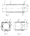
- the cylindrical shipping tube 1 is in the cuboid stabilizing element 2 with a square cross section so that the four inner surfaces of the stabilizing element 2 offset by 90 ° on the top of the shipping tube 1 issue.
- the side surfaces point in the direction strip-shaped tabs 3, 4, 5, 6 extending along the longitudinal axis at least on one, but preferably at both ends.
- the tabs 3, 4, 5 and 6 are on hers Provide underside with an adhesive connector, which is directly on the outer surface of the Shipping tube 1 is set.
- the adhesive connector is preferably an adhesive that adheres to the peripheral surface of the shipping tube 1 is pressed and thus an adhesive connection with him.
- This embodiment is shown in Fig. 1, the adhesive layer, e.g. in the form of an adhesive layer, shown at 7, 8, which is a firm connection between shipping tube 1 and stabilizing element 2.
- an adhesive strip 9 is shown, which in Circumferential direction is wound and the tabs 3, 4, 5, 6 and the tabs Adjacent locations of the shipping tube in the circumferential direction and then in enclose axial direction, so that it is also a safe and non-slip Connection between shipping tube and stabilizing element is achieved.
- the shipping tube 10 is a conventional packaging container made of cardboard or the like, which picks up rolled material and protects it from damage during shipping protects.
- the shipping tube 10 is surrounded by a rectangular envelope 11 enclosed, which is a one-piece cardboard blank and from a bottom 12, Side walls 13, 14, top wall 15 and front and rear swivel flap 16, 17 exists.
- the distance between the side walls 16, 17 corresponds to the diameter of the Shipping tube 10 so that the shipping tube 10 from the side walls and the Bottom wall of the wrapper is set.
- front and rear swing flaps 16, 17 formed, the pivot lines of the form the front and rear end of the top wall 15.
- the swivel flaps 16, 17 have lugs or the like.
- the lugs 18, 19 are Punching on the blank, which are formed in the plane of the swivel flaps and when pivoting the swivel flaps down into the slots 20, 21 of the Snap the side panels into place.
- the free outer edge of the swivel flaps 16, 17 is in each case part-circular Rounding or recess 22 provided, the curvature of the curvature the outer surface of the shipping tube 10 is adapted so that the engagement between Swing flap and shipping tube over part of the circumference of the shipping tube takes place and thus a locking intervention between the two is achieved.
- an adhesive layer 23 strip or dot
- This release film is removed when the shipping tube 10 in the Envelope 11 is introduced.
- the shipping tube 10 is after insertion to the Bottom and thus pressed against the central adhesive layer 23.
- This adhesive layer 23 can be in the form of a continuous adhesive strip or in the form of partial strips or Glue points should be formed.
- the free edge 25 of the Swing flap 16, 17, an adhesive layer 26 may be provided to increase the Locking effect between swivel flap and shipping tube an adhesive connection results.
- the adhesive layer 26 itself can form a linear adhesive connection; however, the arrangement can also be such that on the free edge of the Swing flap 16, 17 is punched a tab with an adhesive layer is provided, which instead of locking via lugs and slots the shipping tube 10 improved.
- a sticker is indicated in Fig. 5, which for shipping or transport and contains data and information required by the shipping company.
Landscapes
- Engineering & Computer Science (AREA)
- Mechanical Engineering (AREA)
- Packaging Of Annular Or Rod-Shaped Articles, Wearing Apparel, Cassettes, Or The Like (AREA)
- Character Discrimination (AREA)
- Lining Or Joining Of Plastics Or The Like (AREA)
- Shaping By String And By Release Of Stress In Plastics And The Like (AREA)
- Cable Accessories (AREA)
Abstract
Description
- Fig. 1
- ein quaderförmiges Stabilisierelement mit zylindrischem Versandrohr, in Seitenansicht,
- Fig. 2
- eine Frontansicht der Darstellung nach Fig. 1,
- Fig. 3
- eine Variante der Verbindung zwischen Stabilisierelement und Versandrohr,
- Fig. 4
- eine weitere Ausführungsform des erfindungsgemäßen Versandrohres mit Stabilisierelement, in Seitenansicht,
- Fig. 5
- eine Vorderansicht der Darstellung nach Fig. 4, teilweise im Schnitt, und
- Fig. 6
- einen Zuschnitt des quaderförmigen Umhüllers mit geänderten Abmessungen.
Claims (12)
- Zylindrisches Versandrohr mit einem Stabilisierelement, das die Position des Versandrohres einer Erkennungsvorrichtung in einer Sortieranlage zum Auslesen der den Versand betreffenden Informationen (Adressen-, Leit- und Gebühren-Informationen) eindeutig zuordnet, dadurch gekennzeichnet, dass das zylindrische Versandrohr (1) von einem beidseitig offenen quaderförmigen Umhüller (2) allseitig umschlossen ist, und dass der Umhüller (2) mit dem Versandrohr (1) durch eine Klebeverbindung (7, 8; 9) verbunden ist.
- Versandrohr nach Anspruch 1, dadurch gekennzeichnet, dass der Umhüller (2) mindestens an einem Verbindungsende mit dem Versandrohr (1) mittig von jeder der Seitenwände ausgehende Laschen (3, 4, 5, 6) aufweist, die mit der Umfangsfläche des Versandrohres (1) durch Klebeverbindung (7, 8; 9) befestigt sind.
- Versandrohr nach Anspruch 2, dadurch gekennzeichnet, dass die Laschen (3, 4, 5, 6) auf ihrer dem Versandrohr (1) zugewandten Seite einen Kleberauftrag (7, 8) mit einer Abziehschicht aufweisen, die vor der Herstellung der Klebeverbindung mit dem Versandrohr (1) entfernt wird, wobei die Laschen mit der Klebeschicht an das Versandrohr angedrückt werden.
- Versandrohr nach Anspruch 1 oder 2, dadurch gekennzeichnet, dass die auf den vier Seiten des Umhüllers (2) vorgesehenen Laschen (3, 4, 5, 6) mit Hilfe eines die Laschen verbindenden Klebebandes (9) mit dem Versandrohr (1) verbunden sind.
- Zylindrisches Versandrohr nach Anspruch 1, dadurch gekennzeichnet, dass das zylindrische Versandrohr (10) von einem an beiden Enden offenen, quaderförmigen Umhüller (11) bzw. einer Hülle umschlossen ist, und dass der Umhüller (11) auf der Innenseite seiner Bodenfläche (12) eine Klebeschicht (23) aufweist, die mit der Unterseite der Versandrohr (10) eine Klebeverbindung ausbildet.
- Versandrohr nach Anspruch 5, dadurch gekennzeichnet, dass die Dimension der Schmalseiten (12, 15) des quaderförmigen Umhüllers (11) dem Durchmesser der Versandrolle (10) angepasst ist, und dass die Dimension der Breitseiten (13, 14) des quaderförmigen Umhüllers (11) der Dimension des Aufklebers (27) auf dem Stabilisierelement entspricht, der die Adressen- bzw. Leit- und Gebühren-Informationen für den Versand enthält.
- Versandrohr nach Anspruch 5 oder 6, dadurch gekennzeichnet, dass die schmale Deckseite (16) des quaderförmigen Umhüllers (11) an beiden Endabschnitten als Schwenkklappe (16, 17) ausgebildet ist, die nach unten klappbar ist und gegen die Oberkante des Versandrohres (10) anliegt sowie das Versandrohr (10) arretiert.
- Versandrohr nach Anspruch 7, dadurch gekennzeichnet, dass die Schwenkklappen (16, 17) an ihren Seitenrändern vorstehende Nasen (18, 19) aufweisen, die in Schlitze (20, 21) in den Seitenwänden (13, 14) des quaderförmigen Umhüllers (11) eingreifen und die so positioniert sind, dass der Eingriff der Nasen in die Schlitze bei nach unten geschwenkter und auf dem Versandrohr aufstehender Klappe stattfindet.
- Versandrohr nach Anspruch 7 oder 8, dadurch gekennzeichnet, dass die Klappe (16, 17) an ihrem freien Rand teilkreisförmig (22) der Umfangskrümmung des Versandrohres (10) angepasst ausgebildet ist.
- Versandrohr nach einem der Ansprüche 5 - 9, dadurch gekennzeichnet, dass vorderes und hinteres Ende des Umhüllers (11) mit gleichen Klappen (16, 17) ausgebildet sind.
- Versandrohr nach einem der Ansprüche 5 - 7, 9, 10, dadurch gekennzeichnet, dass die freie Kante der Klappe eine zusätzliche Klebeverbindung (24) mit der Oberseite des Versandrohres (10) aufweist.
- Versandrohr nach Anspruch 8, dadurch gekennzeichnet, dass die Schlitze (20, 21) in einem kleinen Winkel (α) zur Vertikalen gegen die Mitte des Umhüllers (11) geneigt sind, und die Klappe zum Einrasten der Nasen in die Schlitze um einen Winkel von 90° + α nach unten geschwenkt wird.
Applications Claiming Priority (4)
| Application Number | Priority Date | Filing Date | Title |
|---|---|---|---|
| DE20109914U | 2001-06-18 | ||
| DE20109913U DE20109913U1 (de) | 2001-06-18 | 2001-06-18 | Stabilisierelement für zylindrisches Versandrohr |
| DE20109913U | 2001-06-18 | ||
| DE20109914U DE20109914U1 (de) | 2001-06-18 | 2001-06-18 | Zylindrisches Versandrohr mit Stabilisierungselement |
Publications (2)
| Publication Number | Publication Date |
|---|---|
| EP1270436A1 true EP1270436A1 (de) | 2003-01-02 |
| EP1270436B1 EP1270436B1 (de) | 2008-10-01 |
Family
ID=26057041
Family Applications (1)
| Application Number | Title | Priority Date | Filing Date |
|---|---|---|---|
| EP02012283A Expired - Lifetime EP1270436B1 (de) | 2001-06-18 | 2002-06-05 | Zylindrisches Versandrohr mit Stabilisierelement |
Country Status (3)
| Country | Link |
|---|---|
| EP (1) | EP1270436B1 (de) |
| AT (1) | ATE409657T1 (de) |
| DE (1) | DE50212824D1 (de) |
Cited By (1)
| Publication number | Priority date | Publication date | Assignee | Title |
|---|---|---|---|---|
| CN112638791A (zh) * | 2018-09-21 | 2021-04-09 | 住友化学株式会社 | 圆筒状溅射靶的捆包体的制造方法及捆包体 |
Citations (5)
| Publication number | Priority date | Publication date | Assignee | Title |
|---|---|---|---|---|
| GB832302A (en) * | 1957-02-25 | 1960-04-06 | Robert Samuel Shelly | Multi-tube structures for example for containers and method of making same |
| WO1982003062A1 (en) * | 1981-03-03 | 1982-09-16 | Sandberg Jonny Bengt | A holder for keeping rolled sheets |
| DE29504869U1 (de) * | 1995-03-22 | 1995-06-01 | Müller, Erich, 93086 Wörth | Verdrehsicherung für Rundrohre, Rollen o.dgl. für den Postversand |
| DE20105528U1 (de) * | 2001-03-28 | 2001-06-13 | Müller, Dietrich, 94356 Kirchroth | Zylindrisches Versandrohr mit Umhüller |
| DE20107727U1 (de) * | 2001-05-09 | 2001-08-09 | Müller, Dietrich, 94356 Kirchroth | Zylindrisches Versandrohr mit Stabilisierelement |
-
2002
- 2002-06-05 AT AT02012283T patent/ATE409657T1/de active
- 2002-06-05 DE DE50212824T patent/DE50212824D1/de not_active Expired - Lifetime
- 2002-06-05 EP EP02012283A patent/EP1270436B1/de not_active Expired - Lifetime
Patent Citations (5)
| Publication number | Priority date | Publication date | Assignee | Title |
|---|---|---|---|---|
| GB832302A (en) * | 1957-02-25 | 1960-04-06 | Robert Samuel Shelly | Multi-tube structures for example for containers and method of making same |
| WO1982003062A1 (en) * | 1981-03-03 | 1982-09-16 | Sandberg Jonny Bengt | A holder for keeping rolled sheets |
| DE29504869U1 (de) * | 1995-03-22 | 1995-06-01 | Müller, Erich, 93086 Wörth | Verdrehsicherung für Rundrohre, Rollen o.dgl. für den Postversand |
| DE20105528U1 (de) * | 2001-03-28 | 2001-06-13 | Müller, Dietrich, 94356 Kirchroth | Zylindrisches Versandrohr mit Umhüller |
| DE20107727U1 (de) * | 2001-05-09 | 2001-08-09 | Müller, Dietrich, 94356 Kirchroth | Zylindrisches Versandrohr mit Stabilisierelement |
Cited By (1)
| Publication number | Priority date | Publication date | Assignee | Title |
|---|---|---|---|---|
| CN112638791A (zh) * | 2018-09-21 | 2021-04-09 | 住友化学株式会社 | 圆筒状溅射靶的捆包体的制造方法及捆包体 |
Also Published As
| Publication number | Publication date |
|---|---|
| EP1270436B1 (de) | 2008-10-01 |
| DE50212824D1 (de) | 2008-11-13 |
| ATE409657T1 (de) | 2008-10-15 |
Similar Documents
| Publication | Publication Date | Title |
|---|---|---|
| DE102020214724A1 (de) | Haltevorrichtung für Behälter, insbesondere Dosen, Zuschnitt hierfür und Gebinde hiermit | |
| DE2839913C2 (de) | Schachtel zum Verpacken von länglichen Gegenständen, insbesondere Ampullen | |
| DE3127334A1 (de) | "schachtel fuer eine bandkassette" | |
| DE2821623C2 (de) | Spenderfaltschachtel für eine Spirale mit elektronischen Komponenten | |
| DE8328150U1 (de) | Anhaenger fuer einen Behaelter | |
| DE2251685C3 (de) | Aus einem Zuschnitt gefalteter kastenförmiger Trager für Flaschen | |
| DE69812279T2 (de) | Verpackungsschachtel mit einer Halterungsvorrichtung | |
| DE602004002233T2 (de) | Präsentierschachtel mit Elementen zum Verhindern der Drehung und der Verschiebung eines in die Schachtel eingelegten Behälters | |
| DE69727267T2 (de) | Träger zum Verpacken von rohrförmigen Elementen mit variierenden Längen | |
| DE9005868U1 (de) | Metallverpackung mit siegelbarem Profilrand | |
| EP1270436A1 (de) | Stabilisierelement für zylindrisches Versandrohr | |
| DE4316749A1 (de) | Ein Etikett, das zusammen mit der Oberfläche einer Flasche oder eines Behälters einen Aufnahmeraum für Beipackzettel (Packungsbeilage) bildet und gegen Bruch und Lichteinwirkung schützt | |
| DE60132030T2 (de) | Verpackung für rohrförmige Gegenstände mit Zubehörteilen sowie Inspektionsfenster | |
| DE29504700U1 (de) | Aus einstückigem Karton- oder Pappezuschnitt bestehendes Behältnis mit konvexwandigem, gleichbleibendem Querschnitt | |
| DE20109914U1 (de) | Zylindrisches Versandrohr mit Stabilisierungselement | |
| DE20109913U1 (de) | Stabilisierelement für zylindrisches Versandrohr | |
| DE19819176C2 (de) | Vorrichtung zum Verpacken von Leuchtstoff-Ringlampen | |
| DE29803148U1 (de) | Flächiger Zuschnitt zur Herstellung eines Trägers für den Transport von Flaschen bzw. flaschenartigen Behältern | |
| DE102018123312B4 (de) | Kombinationsverpackung insbesondere für Flaschen | |
| DE9101626U1 (de) | Verpackung für Videokassetten | |
| DE9408308U1 (de) | Versandverpackung | |
| DE9405322U1 (de) | Packschachtel | |
| DE29504869U1 (de) | Verdrehsicherung für Rundrohre, Rollen o.dgl. für den Postversand | |
| DE20107727U1 (de) | Zylindrisches Versandrohr mit Stabilisierelement | |
| DE1486205C3 (de) | Verpackungsboden aus Pappe oder ähnlichem Material |
Legal Events
| Date | Code | Title | Description |
|---|---|---|---|
| PUAI | Public reference made under article 153(3) epc to a published international application that has entered the european phase |
Free format text: ORIGINAL CODE: 0009012 |
|
| AK | Designated contracting states |
Kind code of ref document: A1 Designated state(s): AT BE CH CY DE DK ES FI FR GB GR IE IT LI LU MC NL PT SE TR |
|
| AX | Request for extension of the european patent |
Free format text: AL;LT;LV;MK;RO;SI |
|
| 17P | Request for examination filed |
Effective date: 20030603 |
|
| AKX | Designation fees paid |
Designated state(s): AT BE CH CY DE DK ES FI FR GB GR IE IT LI LU MC NL PT SE TR |
|
| 17Q | First examination report despatched |
Effective date: 20040701 |
|
| RTI1 | Title (correction) |
Free format text: CYLINDRICAL MAIL TUBE WITH STABILISING ELEMENT |
|
| GRAP | Despatch of communication of intention to grant a patent |
Free format text: ORIGINAL CODE: EPIDOSNIGR1 |
|
| GRAS | Grant fee paid |
Free format text: ORIGINAL CODE: EPIDOSNIGR3 |
|
| GRAA | (expected) grant |
Free format text: ORIGINAL CODE: 0009210 |
|
| AK | Designated contracting states |
Kind code of ref document: B1 Designated state(s): AT BE CH CY DE DK ES FI FR GB GR IE IT LI LU MC NL PT SE TR |
|
| REG | Reference to a national code |
Ref country code: GB Ref legal event code: FG4D Free format text: NOT ENGLISH |
|
| REG | Reference to a national code |
Ref country code: CH Ref legal event code: EP |
|
| REG | Reference to a national code |
Ref country code: IE Ref legal event code: FG4D Free format text: LANGUAGE OF EP DOCUMENT: GERMAN |
|
| REF | Corresponds to: |
Ref document number: 50212824 Country of ref document: DE Date of ref document: 20081113 Kind code of ref document: P |
|
| REG | Reference to a national code |
Ref country code: CH Ref legal event code: NV Representative=s name: LUCHS & PARTNER PATENTANWAELTE |
|
| NLV1 | Nl: lapsed or annulled due to failure to fulfill the requirements of art. 29p and 29m of the patents act | ||
| REG | Reference to a national code |
Ref country code: IE Ref legal event code: FD4D |
|
| PG25 | Lapsed in a contracting state [announced via postgrant information from national office to epo] |
Ref country code: ES Free format text: LAPSE BECAUSE OF FAILURE TO SUBMIT A TRANSLATION OF THE DESCRIPTION OR TO PAY THE FEE WITHIN THE PRESCRIBED TIME-LIMIT Effective date: 20090112 |
|
| PG25 | Lapsed in a contracting state [announced via postgrant information from national office to epo] |
Ref country code: NL Free format text: LAPSE BECAUSE OF FAILURE TO SUBMIT A TRANSLATION OF THE DESCRIPTION OR TO PAY THE FEE WITHIN THE PRESCRIBED TIME-LIMIT Effective date: 20081001 Ref country code: PT Free format text: LAPSE BECAUSE OF FAILURE TO SUBMIT A TRANSLATION OF THE DESCRIPTION OR TO PAY THE FEE WITHIN THE PRESCRIBED TIME-LIMIT Effective date: 20090302 Ref country code: FI Free format text: LAPSE BECAUSE OF FAILURE TO SUBMIT A TRANSLATION OF THE DESCRIPTION OR TO PAY THE FEE WITHIN THE PRESCRIBED TIME-LIMIT Effective date: 20081001 |
|
| PG25 | Lapsed in a contracting state [announced via postgrant information from national office to epo] |
Ref country code: DK Free format text: LAPSE BECAUSE OF FAILURE TO SUBMIT A TRANSLATION OF THE DESCRIPTION OR TO PAY THE FEE WITHIN THE PRESCRIBED TIME-LIMIT Effective date: 20081001 Ref country code: IE Free format text: LAPSE BECAUSE OF FAILURE TO SUBMIT A TRANSLATION OF THE DESCRIPTION OR TO PAY THE FEE WITHIN THE PRESCRIBED TIME-LIMIT Effective date: 20081001 |
|
| PLBE | No opposition filed within time limit |
Free format text: ORIGINAL CODE: 0009261 |
|
| STAA | Information on the status of an ep patent application or granted ep patent |
Free format text: STATUS: NO OPPOSITION FILED WITHIN TIME LIMIT |
|
| PG25 | Lapsed in a contracting state [announced via postgrant information from national office to epo] |
Ref country code: IT Free format text: LAPSE BECAUSE OF FAILURE TO SUBMIT A TRANSLATION OF THE DESCRIPTION OR TO PAY THE FEE WITHIN THE PRESCRIBED TIME-LIMIT Effective date: 20081001 Ref country code: SE Free format text: LAPSE BECAUSE OF FAILURE TO SUBMIT A TRANSLATION OF THE DESCRIPTION OR TO PAY THE FEE WITHIN THE PRESCRIBED TIME-LIMIT Effective date: 20090101 |
|
| 26N | No opposition filed |
Effective date: 20090702 |
|
| BERE | Be: lapsed |
Owner name: MULLER, DIETRICH Effective date: 20090630 |
|
| PG25 | Lapsed in a contracting state [announced via postgrant information from national office to epo] |
Ref country code: MC Free format text: LAPSE BECAUSE OF NON-PAYMENT OF DUE FEES Effective date: 20090630 |
|
| GBPC | Gb: european patent ceased through non-payment of renewal fee |
Effective date: 20090605 |
|
| PG25 | Lapsed in a contracting state [announced via postgrant information from national office to epo] |
Ref country code: GB Free format text: LAPSE BECAUSE OF NON-PAYMENT OF DUE FEES Effective date: 20090605 |
|
| PG25 | Lapsed in a contracting state [announced via postgrant information from national office to epo] |
Ref country code: BE Free format text: LAPSE BECAUSE OF NON-PAYMENT OF DUE FEES Effective date: 20090630 |
|
| PG25 | Lapsed in a contracting state [announced via postgrant information from national office to epo] |
Ref country code: GR Free format text: LAPSE BECAUSE OF FAILURE TO SUBMIT A TRANSLATION OF THE DESCRIPTION OR TO PAY THE FEE WITHIN THE PRESCRIBED TIME-LIMIT Effective date: 20090102 |
|
| PGFP | Annual fee paid to national office [announced via postgrant information from national office to epo] |
Ref country code: CH Payment date: 20100614 Year of fee payment: 9 |
|
| PG25 | Lapsed in a contracting state [announced via postgrant information from national office to epo] |
Ref country code: LU Free format text: LAPSE BECAUSE OF NON-PAYMENT OF DUE FEES Effective date: 20090605 |
|
| PG25 | Lapsed in a contracting state [announced via postgrant information from national office to epo] |
Ref country code: TR Free format text: LAPSE BECAUSE OF FAILURE TO SUBMIT A TRANSLATION OF THE DESCRIPTION OR TO PAY THE FEE WITHIN THE PRESCRIBED TIME-LIMIT Effective date: 20081001 |
|
| PGFP | Annual fee paid to national office [announced via postgrant information from national office to epo] |
Ref country code: AT Payment date: 20110613 Year of fee payment: 10 |
|
| PG25 | Lapsed in a contracting state [announced via postgrant information from national office to epo] |
Ref country code: CY Free format text: LAPSE BECAUSE OF FAILURE TO SUBMIT A TRANSLATION OF THE DESCRIPTION OR TO PAY THE FEE WITHIN THE PRESCRIBED TIME-LIMIT Effective date: 20081001 |
|
| REG | Reference to a national code |
Ref country code: CH Ref legal event code: PL |
|
| PG25 | Lapsed in a contracting state [announced via postgrant information from national office to epo] |
Ref country code: CH Free format text: LAPSE BECAUSE OF NON-PAYMENT OF DUE FEES Effective date: 20110630 Ref country code: LI Free format text: LAPSE BECAUSE OF NON-PAYMENT OF DUE FEES Effective date: 20110630 |
|
| PGFP | Annual fee paid to national office [announced via postgrant information from national office to epo] |
Ref country code: DE Payment date: 20120629 Year of fee payment: 11 |
|
| PGFP | Annual fee paid to national office [announced via postgrant information from national office to epo] |
Ref country code: FR Payment date: 20120705 Year of fee payment: 11 |
|
| REG | Reference to a national code |
Ref country code: AT Ref legal event code: MM01 Ref document number: 409657 Country of ref document: AT Kind code of ref document: T Effective date: 20120605 |
|
| PG25 | Lapsed in a contracting state [announced via postgrant information from national office to epo] |
Ref country code: AT Free format text: LAPSE BECAUSE OF NON-PAYMENT OF DUE FEES Effective date: 20120605 |
|
| REG | Reference to a national code |
Ref country code: DE Ref legal event code: R082 Ref document number: 50212824 Country of ref document: DE |
|
| REG | Reference to a national code |
Ref country code: DE Ref legal event code: R119 Ref document number: 50212824 Country of ref document: DE Effective date: 20140101 |
|
| REG | Reference to a national code |
Ref country code: FR Ref legal event code: ST Effective date: 20140228 |
|
| PG25 | Lapsed in a contracting state [announced via postgrant information from national office to epo] |
Ref country code: DE Free format text: LAPSE BECAUSE OF NON-PAYMENT OF DUE FEES Effective date: 20140101 |
|
| PG25 | Lapsed in a contracting state [announced via postgrant information from national office to epo] |
Ref country code: FR Free format text: LAPSE BECAUSE OF NON-PAYMENT OF DUE FEES Effective date: 20130701 |