EP1270795B1 - Automatische Maschine zum Bügeln von Hosen wie Jeans oder elastischer Hosen oder Sporthosen - Google Patents
Automatische Maschine zum Bügeln von Hosen wie Jeans oder elastischer Hosen oder Sporthosen Download PDFInfo
- Publication number
- EP1270795B1 EP1270795B1 EP01115894A EP01115894A EP1270795B1 EP 1270795 B1 EP1270795 B1 EP 1270795B1 EP 01115894 A EP01115894 A EP 01115894A EP 01115894 A EP01115894 A EP 01115894A EP 1270795 B1 EP1270795 B1 EP 1270795B1
- Authority
- EP
- European Patent Office
- Prior art keywords
- trousers
- ironing machine
- assembly
- automatic ironing
- steam
- Prior art date
- Legal status (The legal status is an assumption and is not a legal conclusion. Google has not performed a legal analysis and makes no representation as to the accuracy of the status listed.)
- Expired - Lifetime
Links
- 238000010409 ironing Methods 0.000 title claims abstract description 57
- 239000004744 fabric Substances 0.000 claims abstract description 47
- 238000000429 assembly Methods 0.000 claims abstract description 17
- 230000000712 assembly Effects 0.000 claims abstract description 17
- 210000004197 pelvis Anatomy 0.000 claims description 34
- 230000007480 spreading Effects 0.000 claims description 25
- 238000003892 spreading Methods 0.000 claims description 25
- 238000012545 processing Methods 0.000 claims description 12
- 238000010025 steaming Methods 0.000 claims description 8
- 238000007664 blowing Methods 0.000 claims description 7
- 238000004513 sizing Methods 0.000 claims description 7
- 239000000463 material Substances 0.000 claims description 5
- 230000008878 coupling Effects 0.000 claims description 4
- 238000010168 coupling process Methods 0.000 claims description 4
- 238000005859 coupling reaction Methods 0.000 claims description 4
- 238000004891 communication Methods 0.000 claims description 2
- 238000006073 displacement reaction Methods 0.000 claims description 2
- 229910052751 metal Inorganic materials 0.000 claims description 2
- 238000003825 pressing Methods 0.000 claims description 2
- 238000007599 discharging Methods 0.000 claims 1
- 239000002184 metal Substances 0.000 claims 1
- 229920006395 saturated elastomer Polymers 0.000 claims 1
- 238000000034 method Methods 0.000 description 4
- XEEYBQQBJWHFJM-UHFFFAOYSA-N Iron Chemical compound [Fe] XEEYBQQBJWHFJM-UHFFFAOYSA-N 0.000 description 2
- 238000010276 construction Methods 0.000 description 2
- 238000013021 overheating Methods 0.000 description 2
- 230000008569 process Effects 0.000 description 2
- 238000003672 processing method Methods 0.000 description 2
- 230000002860 competitive effect Effects 0.000 description 1
- 238000000151 deposition Methods 0.000 description 1
- 238000010438 heat treatment Methods 0.000 description 1
- 230000002452 interceptive effect Effects 0.000 description 1
- 229910052742 iron Inorganic materials 0.000 description 1
- 238000012986 modification Methods 0.000 description 1
- 230000004048 modification Effects 0.000 description 1
- 230000006641 stabilisation Effects 0.000 description 1
- 238000011105 stabilization Methods 0.000 description 1
- 238000012546 transfer Methods 0.000 description 1
Images










Classifications
-
- D—TEXTILES; PAPER
- D06—TREATMENT OF TEXTILES OR THE LIKE; LAUNDERING; FLEXIBLE MATERIALS NOT OTHERWISE PROVIDED FOR
- D06F—LAUNDERING, DRYING, IRONING, PRESSING OR FOLDING TEXTILE ARTICLES
- D06F71/00—Apparatus for hot-pressing clothes, linen or other textile articles, i.e. wherein there is substantially no relative movement between pressing element and article while pressure is being applied to the article; Similar machines for cold-pressing clothes, linen or other textile articles
- D06F71/18—Apparatus for hot-pressing clothes, linen or other textile articles, i.e. wherein there is substantially no relative movement between pressing element and article while pressure is being applied to the article; Similar machines for cold-pressing clothes, linen or other textile articles specially adapted for pressing particular garments or parts thereof
- D06F71/28—Apparatus for hot-pressing clothes, linen or other textile articles, i.e. wherein there is substantially no relative movement between pressing element and article while pressure is being applied to the article; Similar machines for cold-pressing clothes, linen or other textile articles specially adapted for pressing particular garments or parts thereof for pressing sleeves, trousers, or other tubular garments or tubular parts of garments
- D06F71/29—Trousers
- D06F71/295—Trousers the top portion of trousers
Definitions
- the present invention relates to an automatic machine which has been specifically designed for ironing trousers free of folds, preferably of a jeans type, or made of elasticized or sports fabrics.
- the aim of the present invention is to overcome the above mentioned drawbacks, by providing an automatic machine, specifically designed for ironing trousers free of folds, preferably of a jeans type, or made of elasticized or sports fabric, allowing the possibility of controlling, in a fully automatic manner, an automatic sizing of the trousers, both at the pelvic region and leg region of the user, while consequently controlling the size quality of the cloth article during its ironing operation.
- a main object of the present invention is to provide such an automatic machine which allows to carry out, in a fully automatized manner, a lot of different trouser processing operations.
- Yet another object of the present invention is to provide a trouser ironing machine which, due to its specifically designed construction, is very reliable and safe in operation.
- Yet another object of the present invention is to provide such an automatic trouser ironing machine which can be easily made starting from easily available elements and materials and which, furthermore, is very competitive from a mere economic standpoint.
- an automatic machine for ironing unfolded trousers preferably of a jeans type or made of elasticized or sports fabrics, with the features of claim 1.
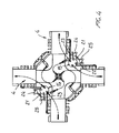
- the automatic ironing machine specifically designed for ironing unfolded trousers, preferably of a jeans type, or made of elasticized or sports fabrics, according to the present invention, which has been generally indicated by the reference number 1, comprises a bearing framework 2, rotatably bearing thereon a carousel element 3 which is provided with four operating assemblies 4 for supporting the cloth articles or trousers being processed or ironed.
- a blower 10 for blowing air inside the several operating assemblies, said blower or blowing unit being coupled to a diffuser 11 which, through adjustment gate 12, communicates with each of said operating assemblies 4, to allow pressurized air to be properly distributed depending on the processing requirements.
- the adjustment gate 12 in particular, is electropneumatically driven for a set time, and can be driven to any desired position during the rotary movement of the carousel 3, for one or more gates simultaneously.
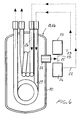
- the automatic ironing machine further comprises a plurality of steaming assemblies, which comprise a first and second steaming drums 15 and 16, respectively, which can be coupled to the mentioned operating assemblies.
- Each steaming drum 15 and 16 is designed for overheating the steam generated by steam boilers, operating under pressure and at a very high temperature.
- the above mentioned device comprises a vessel 20, encompassing each drum, in which a taking or delivery duct 21 is provided, branched into a first branch 22 and a second branch 23, said branches being respectively controlled by a first solenoid valve 24 and a second solenoid valve 25, controlling the communication with a first coil 26 and a second coil 27, arranged inside the envelope 20.
- the device allows the steam held in said envelope or vessel 20 to be easily taken, said steam being held at a pressure of about 5 atm and at a temperature of 150°C.
- the steam will expand and its temperature will decrease up to 100°C, corresponding to a normal atmospheric pressure.
- the steam, after expansion, will be sent into the related coil, arranged inside the mentioned tank where the temperature is of about 150°C.
- the steam will be overheated to a variable volume, so as to achieve a temperature near to that of the pressurized steam.
- the subject automatic ironing machine comprises moreover a rotary coupling, generally indicated by the reference number 28, providing an inlet for the steam and an outlet for the condensate.
- each said operating assembly is specifically designed for processing the cloth articles applied thereto by differently programmed modes of operation.
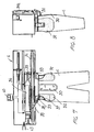
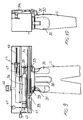
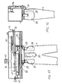
- each operating assembly 4 generally comprises a fixed frontal plate 30, usually made of a net material, to be arranged inside the flap of the cloth article being processed, and being indicated by the reference letter C.
- an outside pressing element 31 driven by a cylinder 31a provided for firmly holding the cloth article being processed, by bearing thereon.
- a pair of pelvis templates or shaped elements On a side of the front plate 30 are provided a pair of pelvis templates or shaped elements, generally indicated by the reference number 32, which are swingably mounted about sliders 33 adapted to be horizontally driven.
- the sliding movement of said sliders is performed by a collecting cogged belt 34, coupling said sliders so as to cause them to be oppositely slidably driven, said belt being coupled, by a fitting element 35, to a pelvis portion spreading cylinder 36.
- Each of said operating assemblies further comprises specifically designed means which are driven depending on the processes to be carried out.
- the pattern driving cylinder 36 is operatively driven to in turn drive the mentioned patterns which are advantageously made of molded and perforated stretched sheet metal elements; in this condition, as a pattern or mold encounters a cloth article, then the operating force will be transmitted to a pneumatic sensor 41 which will provide a pulling operation, depending on a pressure set through the pressure adjusting element 42.
- a second limit switch 43 is operated, for locking said cylinder 36, while holding such a locked position for the overall working cycle, up to the end of the ironing steps.
- a further limit switch 45 arranged on a graduated rod 46 would be used, said graduated rod 46 being designed for interfering against a cam 47 which is operatively coupled to the spreading cylinder 36.
- the cylinder Under a pelvis portion spreading command, the cylinder will start the pelvis portion pulling or tensioning operation, as the cam 47 arrives at the pelvis portion spreading limit switch 45, as fitted on the graduated rod 46.
- the single piston 36 is used, which is driven by setting the pelvis portion spreading amount through the slider including the limit switch 45.
- a detent pad 50 is provided, which can be properly located through the adjustment rod 46, and which constitutes a processing method alternative to the above disclosed method.
- the pad 50 can be properly located by operating a small wheel 51.
- the spreading cylinder 36 is actuated for starting the pulling operation.
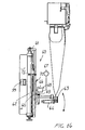
- Each operating assembly comprises moreover a trouser leg pulling or tensioning assembly, generally indicated by the reference number 60 including an operating piston 61 for adjusting the displacement or stroke and locating of the pulling or tensioning assembly 60, which can be slidably driven by a vertical cylinder 62.
- the operating assembly 60 further comprises a pair of grippers 63, which are driven by a gripper cylinder 64, engaging the end portions of the trousers.
- the cylinders 64 are supported by a swinging rod 65 including a pneumatic sensor 66 constituted by a sensor piston, mounted on a swinging rod and being controlled by a pressure reducing unit for properly pulling the trouser legs 67.
- a pneumatic sensor 66 constituted by a sensor piston, mounted on a swinging rod and being controlled by a pressure reducing unit for properly pulling the trouser legs 67.
- leg pulling limit switch 68 and an adjusting spring 69 operating on the swinging rod are provided.
- the operating cylinder 62 Upon a command related to the trouser leg elongation operation, the operating cylinder 62 will start the pulling or tensioning step.
- an elongation limit switch 68 is actuated for controlling a valve 99 of the vertical cylinder 64, and for locking said cylinder for the overall processing or working cycle.
- the trouser leg can be properly pulled or tensioned by using an electric-pneumatic detent element.
- a vertical graduated rod 70 is provided on a vertical cylinder 62, and on said graduated rod 70 is provided an electric limit switch 71.
- a plurality of cams 72 are provided.
- the cylinder 62 Under a trouser leg elongation command, the cylinder 62 starts the tensioning operation and, as the cams 72 engage with the limit switch 71, arranged on said graduated rod, then said cylinder will be locked through the valve 99, while holding this locked position for the overall working cycle.
- the machine comprises moreover an assembly for taking the processed cloth articles or trousers, said taking assembly being generally indicated by the reference number 80.
- said taking or removing assembly comprises a pair of removing grippers 81 which are mounted on movable arms 82, which can be driven toward and away from the region wherein are arranged the mentioned operating assemblies 4, by a slanted pane guide 83, on which is driven a carriage 84 bearing a vertically movable supporting assembly 85 for supporting the arms 82.
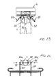
- Each gripper 81 comprises a supporting plate 90, thereon a gripper hook element 91 is articulated, said gripper hook element being turned by a gripper cylinder 92, for engaging in cutouts 32' defined by the pattern 32.
- a further pad 93 for allowing the grippers to hold the trousers at the belt height is provided.
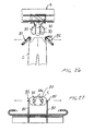
- the grippers are herein represented in a spaced apart position and are so driven as to engage said patterns, as shown in figure 22.
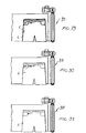
- the grippers 81 engage the cloth article or trousers at the belt level, then the patterns 32 will be caused to be withdrawn (figures 23 to 25), the trousers being held supported by the grippers.
- Said grippers by operating a driving cylinder supporting the assembly 85, are downward driven to deposit the processed cloth article on a conveyor belt 95, which can be continuously driven or so driven as to provide a partial overlapping of the cloth articles or to provide an alternating overlapping thereof.
- the cloth articles, as automatically processed, will be then removed from the machine through the conveyor belt 95 allowing to arrange said cloth articles as desired.
- an automatic ironing machine which allows to process, by differently programmable mode of operation, a plurality of cloth articles or trousers.
- the ironing and setting operations can be performed in a fully automatic manner by the subject apparatus which, being of a transfer type, allows to simultaneously use a plurality of operating stations, in which it is possible to successively perform conventional ironing operations, by overheated steam and pressurized air jets.
- the used materials, as well as the contingent size and shapes can be any, depending on requirements.
Landscapes
- Engineering & Computer Science (AREA)
- Textile Engineering (AREA)
- Treatment Of Fiber Materials (AREA)
- Professional, Industrial, Or Sporting Protective Garments (AREA)
Claims (20)
- Automatische Bügelmaschine (1), zum Bügeln von Hosen ohne Falten, bevorzugt von jeansartigen Hosen oder Hosen aus elastischen oder Sportstoffen, wobei die Maschine ein Traggestell (2) umfasst, das drehbar ein Karussellelement (3) trägt, das eine Vielzahl von programmierbaren Betriebsanordnungen (4) trägt, um die Hosen in Verarbeitung zu tragen, wobei die Betriebsanordnungen dazu geeignet sind, um an eine Hosendampfbügeldampf generierende Anordnung (15, 16, 28) zum Dampfbügeln von Hosen, die auf die. Maschine geladen sind, gekoppelt zu werden, wobei die Betriebsanordnung (4) eine feststehende Vorderplatte (30) umfasst, die in einem Futter (C) der Hosen in Verarbeitung angeordnet sein kann, und dass an der Platte (30) ein Presselement (31), das von einem Zylinder (31a) angetrieben wird, um die Hosen in Verarbeitung festzuhalten, eine die verarbeiteten oder gebügelten Hosen aufnehmende oder entfernende Anordnung (80, 81, 82, 83, 84, 85, 90, 91, 92) und ein Förderband (95) für verarbeitete oder gebügelte Hosen bereitgestellt werden, wobei jede Betriebsanordnung (4) dazu geeignet ist, programmiert zu werden, um automatisch viele verschiedene Verarbeitungsgänge auszuführen, in Abhängigkeit von den der Maschine zugeführten Hosen, nach Größen getrennt oder in verschiedenen Größen, wobei jede Betriebsanordnung (4) ferner eine Hosenbeckendehnungs-Betriebsanordnung (32, 36, 38, 39, 40, 41, 42, 43, 44, 45, 46, 47, 50, 51) so wie eine Hosenbeinzug-Betriebsanordnung (60, 61, 62, 63, 64, 65, 66, 67, 68, 69) umfasst, die es ermöglichen, eine automatische Sortierung der Hosen sowohl in einem Beckenbereich als auch in einem Beinbereich davon bereitzustellen, wobei die Beckendehnungsanordnung ein Paar Formbretter (32) für den Hosenbeckenabschnitt umfassen, die neben der Vorderplatte (30) angeordnet sind, wobei die Zuganordnung (60) zudem ein Paar Greifer (63) umfasst, dadurch gekennzeichnet, dass die Formbretter (32) schwenkbar auf waagerecht beweglichen Gleitstücken (33) angebracht sind, dass die Beinzugbetriebsanordnung einen Kolben (61) umfasst, der gleitbar durch einen senkrechten Zylinder (62) angetrieben werden kann, der an das Traggestell (2) gekoppelt ist, dass die Greifer von einem Greiferzylinder (64) angetrieben werden, dass die Formbretter (32) von Antriebsmitteln angetrieben werden, die einen Beckenabschnittdehnzylinder (36) umfassen, der an ein Streckband gekoppelt ist, das die Gleitstücke (33) der Beckenabschnittformbretter (32) koppelt, damit die Gleitstücke (33) in entgegengesetzte Richtungen angetrieben werden können, und dass die Beckendehnungsanordnung ferner ein Verstärkerelement umfasst, um eine Schwenkbewegung des Beckenabschnitt-Formbretts (32) zu verstärken, wobei das Verstärkungselement dazu geeignet ist, mit einem elektrischen Grenzschalter (39) zusammenzuarbeiten, um den Beckenabschnittdehnungszylinder (36) während des Gebrauchs der Dehnungsanordnung an elastischen Stoffen in verschiedenen Größen zu arretieren.
- Automatische Bügelmaschine nach Anspruch 1, dadurch gekennzeichnet, dass die Vorderplatte (30) und die Beckenabschnitt-Formbretter (32) ein Netzelement oder ein perforiertes Blechtafelelement umfassen.
- Automatische Bügelmaschine nach Anspruch 1, dadurch gekennzeichnet, dass die Beckendehnungsanordnung ferner einen Druckluftsensor (41) aufweist, der axial an dem Beckenabschnittdehnungszylinder (36) ausgerichtet angeordnet ist, wobei der Druckluftsensor einen zweiten elektrischen Grenzschalter (43) antreibt, um den Zylinder (36) anzutreiben.
- Automatische Bügelmaschine nach Anspruch 1 bis 3, dadurch gekennzeichnet, dass die Beckendehnungsanordnung ferner einen eingeteilten Stab (46) umfasst, der einen Beckenabschnittdehnungs-Grenzschälter (45) umfasst, der dazu geeignet ist, während eines Sortiervorgangs an Kleidungsstücken getrennter Größen gegen eine Nocke (47) zu wirken, die wirksam an den Beckenabschnittdehnungszylinder (36) gekoppelt ist.
- Automatische Bügelmaschine nach Anspruch 1 bis 4, dadurch gekennzeichnet, dass die Beckendehnungsanordnung ferner einen Sperrklotz (50) umfasst, der auf den eingeteilten Stab (46) gesetzt werden kann, und dass der. Klotz (50) von einem Beckenabschnittdehnungsrad (51) gesteuert wird, während die Maschine für getrennte Kleidüngsstückgrößen betätigt wird.
- Automatische Bügelmaschine nach Anspruch 1, dadurch gekennzeichnet, dass der Greiferzylinder (64) von einem Schwenkstab (65) getragen wird, der einen Druckluftsensor (66) umfasst, der aus einem Kolben besteht, der von einer Druckminderungseinheit (67) gesteuert wird.
- Automatische Bügelmaschine nach Anspruch 6, dadurch gekennzeichnet, dass der Druckluftsensor (66) mit einem Grenzschalter (68) zusammenarbeitet, um die Hosenbeine zu straffen.
- Automatische Bügelmaschine nach Anspruch 6, dadurch gekennzeichnet, dass der Schwingstab (65) von einer Stellfeder (69) gesteuert wird.
- Automatische Bügelmaschine nach Anspruch 6, dadurch gekennzeichnet, dass der Schwingstab (65) an einen elektrischen Grenzschalter (68) gekoppelt ist, wobei ferner Nockenmittel bereitgestellt werden, den elektrischen. Grenzschalter (68) zu betätigen, um den senkrechten Greiferzylinder (64) anzutreiben.
- Automatische Bügelmaschine nach Anspruch 1, dadurch gekennzeichnet, dass die Dampfbügelanordnung innerhalb des Traggestells (2) eine Blaseinheit (10) umfasst, um Druckluft in die Betriebsanordnungen (4) zu blasen, und dass die Blaseinheit (10) an einen Diffusor (11) gekoppelt ist, der mit jeder der Betriebsanordnungen (4) durch einen Stellschieber (12) in Verbindung steht.
- Automatische Bügelmaschine nach Anspruch 10, dadurch gekennzeichnet, dass der Stellschieber (12) von elektrischen Druckluftmitteln angetrieben wird.
- Automatische Bügelmaschine nach Anspruch 10, dadurch gekennzeichnet, dass der Stellschieber (12) in einem beliebigen Drehschritt des Karussells einzeln oder kombiniert angetrieben werden kann.
- Automatische Bügelmaschine nach Anspruch 1, dadurch gekennzeichnet, dass die Dampfbügelanordnung von Dämpfanordnungen (15, 16), die erste und zweite Dämpftrommeln (15, 16) umfassen, mit Bügeldampf versorgt werden, wobei jede der Trommeln an zwei verschiedene Betriebsanordnungen (4) gekoppelt sein kann.
- Automatische Bügelmaschine nach Anspruch 13, dadurch gekennzeichnet, dass jede der Dämpftrommeln (15, 16) einen Dampfbehälter (20) umfasst, der eine Dampfleitung (21) umfasst, an der ein Magnetventil (24, 25) funktioniert, um eine Verbindung mit einer Dampfschlange (26, 27) zu steuern, die in dem Behälter (20) angeordnet ist, und dass der Behälter (20) mit Hochdruck-Sättigungsdampf versorgt wird, und dass am Auslass der Schlange (26, 27) Luftdruck-Heißdampf geliefert wird.
- Automatische Bügelmaschine nach Anspruch 14, dadurch gekennzeichnet, dass für den Behälter (20) erste und zweite Arme (22, 23) bereitgestellt werden, die jeweils von ersten und zweiten Magnetventilen (24, 25) gesteuert werden, wobei jeder Arm (22, 23) mit einer Schlange (26, 27), die in dem Behälter (20) angeordnet ist, in Verbindung steht.
- Automatische Bügelmaschine nach Anspruch 1, dadurch gekennzeichnet, dass die Maschine eine Rotationskopplung (28) umfasst, um das Eintreten von Dampf und das Ablassen von Kondensationsprodukten zu erlauben.
- Automatische Bügelmaschine nach Anspruch 1, dadurch gekennzeichnet, dass die verarbeitete Hosen aufnehmende Anordnung (80) ein Paar Greifer (81) umfasst, die an Greiferarmen (82) angebracht sind, die zu oder von einem Bereich angetrieben werden können, indem die Betriebsanordnungen (4) funktionieren.
- Automatische Bügelmaschine nach Anspruch 17, dadurch gekennzeichnet, dass die Arme (82) durch einen senkrecht antreibenden Kolben an einen Schlitten (84) gekoppelt sind, der an eine schräge Planführung (83) gekoppelt ist.
- Automatische Bügelmaschine nach Anspruch 17, dadurch gekennzeichnet, dass jeder Greifer (81) eine Tragplatte (90) umfasst, auf der ein Greiferhakenelement (91) schwenkbar ist, wobei das Greiferhakenelement (91) drehbar von einem Greiferzylinder (92) angetrieben wird, um das Greiferhakenelement (91) in Ausschnitten (32') in Eingriff zu bringen, die von den Beckenabschnitt-Formbrettern (32) definiert werden, wobei ferner ein Anschlagsklotz (93) für die Greifer (81) bereitgestellt wird, um die Kleidungsstücke auf Gurthöhe festzuhalten.
- Automatische Bügelmaschine nach Anspruch 1, dadurch gekennzeichnet, dass das Förderband (95) entweder kontinuierlich oder diskontinuierlich bewegbar ist, indem es unter einem Kleidungsstück-Lösebereich angeordnet ist, und dazu ausgelegt ist, die verarbeiteten Kleidungsstücke zu überlappen oder die verarbeiteten Kleidungsstücke in einem beabstandeten und versetzten Verhältnis anzuordnen.
Priority Applications (3)
| Application Number | Priority Date | Filing Date | Title |
|---|---|---|---|
| EP01115894A EP1270795B1 (de) | 2001-06-29 | 2001-06-29 | Automatische Maschine zum Bügeln von Hosen wie Jeans oder elastischer Hosen oder Sporthosen |
| DE60127242T DE60127242T2 (de) | 2001-06-29 | 2001-06-29 | Automatische Maschine zum Bügeln von Hosen und Jeans oder elastischen Hosen oder Sporthosen |
| AT01115894T ATE356904T1 (de) | 2001-06-29 | 2001-06-29 | Automatische maschine zum bügeln von hosen wie jeans oder elastischer hosen oder sporthosen |
Applications Claiming Priority (1)
| Application Number | Priority Date | Filing Date | Title |
|---|---|---|---|
| EP01115894A EP1270795B1 (de) | 2001-06-29 | 2001-06-29 | Automatische Maschine zum Bügeln von Hosen wie Jeans oder elastischer Hosen oder Sporthosen |
Publications (2)
| Publication Number | Publication Date |
|---|---|
| EP1270795A1 EP1270795A1 (de) | 2003-01-02 |
| EP1270795B1 true EP1270795B1 (de) | 2007-03-14 |
Family
ID=8177892
Family Applications (1)
| Application Number | Title | Priority Date | Filing Date |
|---|---|---|---|
| EP01115894A Expired - Lifetime EP1270795B1 (de) | 2001-06-29 | 2001-06-29 | Automatische Maschine zum Bügeln von Hosen wie Jeans oder elastischer Hosen oder Sporthosen |
Country Status (3)
| Country | Link |
|---|---|
| EP (1) | EP1270795B1 (de) |
| AT (1) | ATE356904T1 (de) |
| DE (1) | DE60127242T2 (de) |
Families Citing this family (3)
| Publication number | Priority date | Publication date | Assignee | Title |
|---|---|---|---|---|
| CN104372595B (zh) * | 2014-11-20 | 2016-07-06 | 宁波裕人智能控制技术有限公司 | 毛衫蒸烫定型机 |
| CN111910407B (zh) * | 2020-08-14 | 2023-03-28 | 杭州纳网信息科技有限公司 | 一种带护膝功能的女士针织瑜伽裤的整烫设备 |
| CN114737342B (zh) * | 2022-04-09 | 2022-11-25 | 丸三浩联科技(浙江)有限公司 | 一种椅套定型整烫装备 |
Family Cites Families (3)
| Publication number | Priority date | Publication date | Assignee | Title |
|---|---|---|---|---|
| GB1409244A (en) * | 1971-09-09 | 1975-10-08 | Weston Laundry Machine Co Ltd | Laundry machines |
| DE7325989U (de) * | 1972-07-18 | 1973-11-29 | Ibis Engineers Ltd | Hosenpresse |
| IT1289068B1 (it) * | 1996-01-24 | 1998-09-25 | Sandro Tasoniero | Impianto automatico per la stiratura e lo scarico di capi di abbigliamento |
-
2001
- 2001-06-29 EP EP01115894A patent/EP1270795B1/de not_active Expired - Lifetime
- 2001-06-29 AT AT01115894T patent/ATE356904T1/de not_active IP Right Cessation
- 2001-06-29 DE DE60127242T patent/DE60127242T2/de not_active Expired - Fee Related
Also Published As
| Publication number | Publication date |
|---|---|
| DE60127242D1 (de) | 2007-04-26 |
| EP1270795A1 (de) | 2003-01-02 |
| ATE356904T1 (de) | 2007-04-15 |
| DE60127242T2 (de) | 2007-12-20 |
Similar Documents
| Publication | Publication Date | Title |
|---|---|---|
| US4728015A (en) | Garment shaping system | |
| US6446369B2 (en) | Automatic machine for ironing trousers such as jeans or elasticized or sports trousers | |
| US3477621A (en) | Method and apparatus for shaping and finishing a garment | |
| US4862608A (en) | Pressing plate multi-directional moving apparatus for a clothes press | |
| CN100497802C (zh) | 用于熨烫或压平衬衫的装置 | |
| US4057179A (en) | Garment pressing machines | |
| CA1272947A (en) | Ironing machine | |
| US3578790A (en) | Cabinet pants press | |
| EP1270795A1 (de) | Automatische Maschine zum Bügeln von Hosen sowie Jeans oder elastischer Hosen oder Sporthosen | |
| US2516054A (en) | Garment press | |
| US2986311A (en) | Method and apparatus for steaming and ironing a clothing having a collar | |
| US3719311A (en) | Pressing apparatus and method | |
| US3055564A (en) | Trousers top finisher | |
| US4473961A (en) | Trouser finisher center buck with vacuum, steaming, and drying apparatus | |
| WO1996025545A1 (en) | Pressing and finishing shirt portions | |
| GB2142938A (en) | Garment pressing machine | |
| US3428228A (en) | Garment-treating machine for outer coats and jackets | |
| EP0138371B1 (de) | Hosenbügelpresse, und Hosenbundspanner für Hosenfinisher | |
| US4479314A (en) | Trouser finisher with independently retractable and extendable waist and leg expanders | |
| SU1606556A1 (ru) | Способ разутюживани швов швейных изделий и устройство дл его осуществлени | |
| WO2003053659A1 (en) | Apparatus for hot applying strips or films on textile or non textile supports | |
| US8006416B2 (en) | Pants pressing machine | |
| US5181333A (en) | Height adjustable pants presser with top finishing | |
| CN101245545B (zh) | 衬衫整烫机 | |
| US4479315A (en) | Steaming apparatus for a vertical side chest in a trouser presser |
Legal Events
| Date | Code | Title | Description |
|---|---|---|---|
| PUAI | Public reference made under article 153(3) epc to a published international application that has entered the european phase |
Free format text: ORIGINAL CODE: 0009012 |
|
| AK | Designated contracting states |
Kind code of ref document: A1 Designated state(s): AT BE CH CY DE DK ES FI FR GB GR IE IT LI LU MC NL PT SE TR |
|
| AX | Request for extension of the european patent |
Free format text: AL;LT;LV;MK;RO;SI |
|
| 17P | Request for examination filed |
Effective date: 20030321 |
|
| AKX | Designation fees paid |
Designated state(s): AT BE CH CY DE DK ES FI FR GB GR IE IT LI LU MC NL PT SE TR |
|
| 17Q | First examination report despatched |
Effective date: 20040810 |
|
| GRAP | Despatch of communication of intention to grant a patent |
Free format text: ORIGINAL CODE: EPIDOSNIGR1 |
|
| GRAS | Grant fee paid |
Free format text: ORIGINAL CODE: EPIDOSNIGR3 |
|
| GRAA | (expected) grant |
Free format text: ORIGINAL CODE: 0009210 |
|
| AK | Designated contracting states |
Kind code of ref document: B1 Designated state(s): AT BE CH CY DE DK ES FI FR GB GR IE IT LI LU MC NL PT SE TR |
|
| PG25 | Lapsed in a contracting state [announced via postgrant information from national office to epo] |
Ref country code: FI Free format text: LAPSE BECAUSE OF FAILURE TO SUBMIT A TRANSLATION OF THE DESCRIPTION OR TO PAY THE FEE WITHIN THE PRESCRIBED TIME-LIMIT Effective date: 20070314 Ref country code: BE Free format text: LAPSE BECAUSE OF FAILURE TO SUBMIT A TRANSLATION OF THE DESCRIPTION OR TO PAY THE FEE WITHIN THE PRESCRIBED TIME-LIMIT Effective date: 20070314 Ref country code: CH Free format text: LAPSE BECAUSE OF FAILURE TO SUBMIT A TRANSLATION OF THE DESCRIPTION OR TO PAY THE FEE WITHIN THE PRESCRIBED TIME-LIMIT Effective date: 20070314 Ref country code: AT Free format text: LAPSE BECAUSE OF FAILURE TO SUBMIT A TRANSLATION OF THE DESCRIPTION OR TO PAY THE FEE WITHIN THE PRESCRIBED TIME-LIMIT Effective date: 20070314 Ref country code: NL Free format text: LAPSE BECAUSE OF FAILURE TO SUBMIT A TRANSLATION OF THE DESCRIPTION OR TO PAY THE FEE WITHIN THE PRESCRIBED TIME-LIMIT Effective date: 20070314 Ref country code: LI Free format text: LAPSE BECAUSE OF FAILURE TO SUBMIT A TRANSLATION OF THE DESCRIPTION OR TO PAY THE FEE WITHIN THE PRESCRIBED TIME-LIMIT Effective date: 20070314 |
|
| REG | Reference to a national code |
Ref country code: GB Ref legal event code: FG4D |
|
| REG | Reference to a national code |
Ref country code: CH Ref legal event code: EP |
|
| REF | Corresponds to: |
Ref document number: 60127242 Country of ref document: DE Date of ref document: 20070426 Kind code of ref document: P |
|
| REG | Reference to a national code |
Ref country code: IE Ref legal event code: FG4D |
|
| PG25 | Lapsed in a contracting state [announced via postgrant information from national office to epo] |
Ref country code: SE Free format text: LAPSE BECAUSE OF FAILURE TO SUBMIT A TRANSLATION OF THE DESCRIPTION OR TO PAY THE FEE WITHIN THE PRESCRIBED TIME-LIMIT Effective date: 20070614 |
|
| PG25 | Lapsed in a contracting state [announced via postgrant information from national office to epo] |
Ref country code: ES Free format text: LAPSE BECAUSE OF FAILURE TO SUBMIT A TRANSLATION OF THE DESCRIPTION OR TO PAY THE FEE WITHIN THE PRESCRIBED TIME-LIMIT Effective date: 20070625 |
|
| PG25 | Lapsed in a contracting state [announced via postgrant information from national office to epo] |
Ref country code: PT Free format text: LAPSE BECAUSE OF FAILURE TO SUBMIT A TRANSLATION OF THE DESCRIPTION OR TO PAY THE FEE WITHIN THE PRESCRIBED TIME-LIMIT Effective date: 20070814 |
|
| NLV1 | Nl: lapsed or annulled due to failure to fulfill the requirements of art. 29p and 29m of the patents act | ||
| REG | Reference to a national code |
Ref country code: CH Ref legal event code: PL |
|
| PLBE | No opposition filed within time limit |
Free format text: ORIGINAL CODE: 0009261 |
|
| STAA | Information on the status of an ep patent application or granted ep patent |
Free format text: STATUS: NO OPPOSITION FILED WITHIN TIME LIMIT |
|
| PG25 | Lapsed in a contracting state [announced via postgrant information from national office to epo] |
Ref country code: DK Free format text: LAPSE BECAUSE OF FAILURE TO SUBMIT A TRANSLATION OF THE DESCRIPTION OR TO PAY THE FEE WITHIN THE PRESCRIBED TIME-LIMIT Effective date: 20070314 Ref country code: MC Free format text: LAPSE BECAUSE OF NON-PAYMENT OF DUE FEES Effective date: 20070630 |
|
| 26N | No opposition filed |
Effective date: 20071217 |
|
| PG25 | Lapsed in a contracting state [announced via postgrant information from national office to epo] |
Ref country code: GR Free format text: LAPSE BECAUSE OF FAILURE TO SUBMIT A TRANSLATION OF THE DESCRIPTION OR TO PAY THE FEE WITHIN THE PRESCRIBED TIME-LIMIT Effective date: 20070615 |
|
| PG25 | Lapsed in a contracting state [announced via postgrant information from national office to epo] |
Ref country code: IE Free format text: LAPSE BECAUSE OF NON-PAYMENT OF DUE FEES Effective date: 20070629 |
|
| PGFP | Annual fee paid to national office [announced via postgrant information from national office to epo] |
Ref country code: IT Payment date: 20080521 Year of fee payment: 8 Ref country code: TR Payment date: 20080508 Year of fee payment: 8 |
|
| PGFP | Annual fee paid to national office [announced via postgrant information from national office to epo] |
Ref country code: DE Payment date: 20080618 Year of fee payment: 8 |
|
| PGFP | Annual fee paid to national office [announced via postgrant information from national office to epo] |
Ref country code: FR Payment date: 20080627 Year of fee payment: 8 |
|
| PGFP | Annual fee paid to national office [announced via postgrant information from national office to epo] |
Ref country code: GB Payment date: 20080509 Year of fee payment: 8 |
|
| PG25 | Lapsed in a contracting state [announced via postgrant information from national office to epo] |
Ref country code: CY Free format text: LAPSE BECAUSE OF FAILURE TO SUBMIT A TRANSLATION OF THE DESCRIPTION OR TO PAY THE FEE WITHIN THE PRESCRIBED TIME-LIMIT Effective date: 20070314 |
|
| PG25 | Lapsed in a contracting state [announced via postgrant information from national office to epo] |
Ref country code: LU Free format text: LAPSE BECAUSE OF NON-PAYMENT OF DUE FEES Effective date: 20070629 |
|
| GBPC | Gb: european patent ceased through non-payment of renewal fee |
Effective date: 20090629 |
|
| REG | Reference to a national code |
Ref country code: FR Ref legal event code: ST Effective date: 20100226 |
|
| PG25 | Lapsed in a contracting state [announced via postgrant information from national office to epo] |
Ref country code: FR Free format text: LAPSE BECAUSE OF NON-PAYMENT OF DUE FEES Effective date: 20090630 |
|
| PG25 | Lapsed in a contracting state [announced via postgrant information from national office to epo] |
Ref country code: GB Free format text: LAPSE BECAUSE OF NON-PAYMENT OF DUE FEES Effective date: 20090629 |
|
| PG25 | Lapsed in a contracting state [announced via postgrant information from national office to epo] |
Ref country code: DE Free format text: LAPSE BECAUSE OF NON-PAYMENT OF DUE FEES Effective date: 20100101 |
|
| PG25 | Lapsed in a contracting state [announced via postgrant information from national office to epo] |
Ref country code: IT Free format text: LAPSE BECAUSE OF NON-PAYMENT OF DUE FEES Effective date: 20090629 |
|
| PG25 | Lapsed in a contracting state [announced via postgrant information from national office to epo] |
Ref country code: TR Free format text: LAPSE BECAUSE OF NON-PAYMENT OF DUE FEES Effective date: 20090629 |