EP1270831A2 - Soupape de vidange pour réservoir de chasse - Google Patents
Soupape de vidange pour réservoir de chasse Download PDFInfo
- Publication number
- EP1270831A2 EP1270831A2 EP02405472A EP02405472A EP1270831A2 EP 1270831 A2 EP1270831 A2 EP 1270831A2 EP 02405472 A EP02405472 A EP 02405472A EP 02405472 A EP02405472 A EP 02405472A EP 1270831 A2 EP1270831 A2 EP 1270831A2
- Authority
- EP
- European Patent Office
- Prior art keywords
- valve
- float
- valve according
- closure body
- auxiliary
- Prior art date
- Legal status (The legal status is an assumption and is not a legal conclusion. Google has not performed a legal analysis and makes no representation as to the accuracy of the status listed.)
- Granted
Links
Images


Classifications
-
- E—FIXED CONSTRUCTIONS
- E03—WATER SUPPLY; SEWERAGE
- E03D—WATER-CLOSETS OR URINALS WITH FLUSHING DEVICES; FLUSHING VALVES THEREFOR
- E03D1/00—Water flushing devices with cisterns ; Setting up a range of flushing devices or water-closets; Combinations of several flushing devices
- E03D1/02—High-level flushing systems
- E03D1/14—Cisterns discharging variable quantities of water also cisterns with bell siphons in combination with flushing valves
- E03D1/142—Cisterns discharging variable quantities of water also cisterns with bell siphons in combination with flushing valves in cisterns with flushing valves
-
- E—FIXED CONSTRUCTIONS
- E03—WATER SUPPLY; SEWERAGE
- E03D—WATER-CLOSETS OR URINALS WITH FLUSHING DEVICES; FLUSHING VALVES THEREFOR
- E03D1/00—Water flushing devices with cisterns ; Setting up a range of flushing devices or water-closets; Combinations of several flushing devices
- E03D1/30—Valves for high or low level cisterns; Their arrangement ; Flushing mechanisms in the cistern, optionally with provisions for a pre-or a post- flushing and for cutting off the flushing mechanism in case of leakage
- E03D1/34—Flushing valves for outlets; Arrangement of outlet valves
Definitions
- the invention relates to a drain valve for a cistern, with an auxiliary valve, which has a closure body, after its actuation is the static pressure of the rinse water automatic opening of the main valve causes.
- a drain valve of this type is known from the prior art DE 2609138 become known.
- This is the closure body of the main valve an up and down movable piston.
- At the Piston is attached to a sealing flange, which is when the cistern is full due to the static pressure on the valve seat of the Main valve rests.
- An upper side of the sealing flange offers is a cylinder space, which after actuation of the Auxiliary valve is relieved of the water pressure.
- This drain valve has the advantage that it is comparatively low Force can be operated.
- To trigger a rinsing process is a pressure on the closure body of the auxiliary valve exercised, which opens the auxiliary valve.
- Cisterns have also been in use for a long time, which also include flushing with a portion of the rinse water, for example 6 liters enable. This saves water on a large scale.
- the invention is based on the object, the drain valve so that a partial rinse with this is possible.
- the valve should still have a simple structure own as well as be reliable and easy to maintain.
- the object is achieved according to claim 1.
- the control of the Auxiliary valve with a float enables this to be closed Auxiliary valve depending on the water level in the cistern and therefore a partial rinse.
- Preferably in one Dual flush two swimmers provided in different Heights are arranged. With the bottom float becomes one Full flushing and partial flushing controlled with the upper float.
- the height of the upper float determines the amount of Rinsing water during partial rinsing.
- This top float is in its height adjustable, so the desired subset can easily and be set precisely at the same time.
- a major advantage of the drain valve according to the invention is seen there that the closing noise during a partial flush is significantly smaller than the previous cisterns, that allow a partial rinse.
- the very annoying blow when closing of the main valve is significantly dampened because the closure body of the main valve is moved by a differential pressure of the water and is therefore completely in the water. The valve body can therefore not suddenly hit the valve seat.
- a further reduction in the flushing noise can then be achieved if the cistern outlet is horizontal.
- the exit is direct and a flushing bow, in which usually Noises can be avoided.
- At least one tie rod provided with the valve body of the auxiliary valve connected is.
- a float is arranged on this tie rod and by means of a latch or other locking device this tie rod is fixed.
- the pull rod can now be unlocked released and a flush is triggered.
- the postponement can be done with little force and enables a mechanical, electromagnetic or pneumatic release. Due to the low power required is a trigger possible with battery operation.
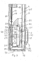
- FIG. 1 to 6 show a cistern 2 in which a drain valve 1 is attached.
- the drain valve 1 is actuated with an actuating device only indicated in FIG. 2 3, which is arranged behind an inspection opening 36 and the one mechanical, electromagnetic, hydraulic or can be pneumatic actuation.
- the in Fig. 2 latch 31 shown in the position shown in Fig. 3 postponed. This shift takes place against the retroactive one Force of a spring 38.
- the drain valve 1 has a main valve 5 and an auxiliary valve 4 on that near a relatively narrow bottom wall 37 of the box body are arranged.
- the main valve 5 has a piston 8, on which a Sealing flange 21 is arranged, which has a valve seat 32 cooperates.
- the piston 8 is horizontal in a valve housing 11 displaceable and in relation to this with an outer circumferential sealing ring 24 sealed.
- a back 39 of the Piston 8 faces a chamber 23, which in FIG Opening 33 of the housing 11 with an interior 40 of the cistern 2 is connected. When the cistern is full is in the Room 40 and room 23 rinse water.
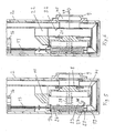
- the interior 40 is also via a passage 22 of the housing 11 with a space 41 connected.
- a front 42 of the piston 8 is this space 41 facing.
- the position of the piston according to FIG. 4 prevails the same water pressure in both rooms 23 and 41.
- a compression spring 28 which on a rear wall 43 of the housing 11th is supported, the piston 8 in that shown in Fig. 4 Position held.
- the main valve 5 is as can be seen closed.
- the auxiliary valve 4 has a rod-shaped closure body 26 on a lower sealing flange 27 and an upper sealing flange 34 has.
- a compression spring 29 is shown in FIG. 4 on one Supported web 44 and holds the closure body 26 in the in Fig. 4 position, in which the lower sealing flange 27 rests on a valve seat 20 of a channel 19.
- the channel 19 leads according to FIG. 4 along and to the bottom wall 37 vertically rising overflow pipe 6, which according to FIG has upper overflow opening 7.
- the channel 19 is horizontal Outlet opening 45 of an outlet nozzle 9 connected.
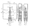
- the valve body 26 with two tie rods 13 and 14 connected, which according to FIGS. 1 to 3 by a lower Float 16 and an upper float 15 passed through are.
- the upper float 15 is in the area of an external thread 17 connected to the pull rod 14.
- the pull rod 14 By turning the pull rod 14 the float 15 can be adjusted in height. in this connection the float 15 is displaceable on two guide rails 12 stored. These rails 12 are on a rear wall 10 of the Cistern body attached.
- the lower float 16 is regarding the pull rod 14 is freely movable in height.
- the lower Float 16 is in the area of an external thread 18 with the pull rod 13 connected. By turning the pull rod 13, the lower one Float 16 can be adjusted in height, this too is slidably guided on the rails 12.
- the float 15 is freely movable. Is the The cistern is filled with rinsing water, so the upper float 15 on the drawbar 14 and the lower float 16 on the drawbar 13 an upward force. Because in the rest position both tie rods 14 and 13 each fixed with a bolt 31 are at rest by these forces Drawbars 13 and 14 are not moving. 2 is only the bolt 31 visible, which engages with the pull rod is. As can be seen, the latch 31 engages in a constriction 35 of the pull rod 13. Another bar, not shown here is engaged with the tie rod 14. Both bars are apart can be operated independently.
- drain valve 1 The operation of the drain valve 1 is explained below.
- the cistern 2 In the starting position, the cistern 2 is filled with rinsing water. The filling takes place in a manner known per se with a fill valve not shown here.
- the piston 8 and the closure body 26 are in the positions shown in FIG. 4.
- the main valve 5 and the auxiliary valve 4 are thus closed.
- the pull rod 13 unlocked.
- the corresponding bolt 31 is shown in FIG. 2 moved to the right. This can be mechanical, electromagnetic, hydraulic or done pneumatically.
- buoyancy the lower float 16 now moves the tie rod 13 above and thereby the closure body 26 is in the in Fig. 5th shown upper position moves.
- the sealing flange 34 lies here as can be seen on the housing 11 and closes the passage 33.
- the sealing flange 27 is now lifted off the valve seat 20 and the space 23 is connected to the channel 19 at the valve seat 20.
- water now flows from space 23 into the Channel 19. This reduces the static pressure in chamber 23.
- the pressure in the chamber 41 is maintained due to the pressure difference of the pistons 8 in FIG moved right to left, the spring 28 being tensioned.
- the Sealing flange 21 is thus lifted from the valve seat 32 and that Main valve 5 opened.
- the water in the cistern flows through the passage 22 into the outlet opening 45 and leaves it in Direction of arrow 47.
- the water flows directly into the rinsing channel a toilet bowl, not shown here.
- the pull rod 14 is unlocked.
- the Auxiliary valve 4 and main valve 5 open as above explained.
- the level of the rinsing water is now about the height of the line 48 shown in broken lines in FIG. 1, this is omitted the buoyancy of the upper float 15 and the pull rod 14 moves down and is automatically by the corresponding Bolt 31 locked.
- the closure body 26 thereby moves in the position shown in Fig. 4. That is the passage 33 open and through this, the chamber 23 from the interior 40 filled with water. This eliminates the pressure difference and the piston 8 through the compression springs 28 in the in Fig. 4th shown locking position moves.
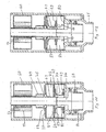
- the drain valve 50 is shown in FIGS. 7 to 12 explained.
- the drain valve 50 is attached to the bottom 66 of a cistern 51 and according to FIG. 10 has a vertically projecting downward Outlet spout 86, which is only partially in one here visible flushing sheet 65 opens out and opposite this with a circumferential lip seal 67 is sealed.
- a valve seat 68 is arranged, which with a piston 70 Main valve 54 forms.
- the piston 70 is in a valve housing 61 limited vertical displacement, with a circumferential sealing lip 71 on the inside on a cylindrical wall 61a of the valve housing 61 slides along.
- a sealing flange 69 is arranged, which is connected to the valve seat 68 cooperates.
- the auxiliary valve 53 with a closure body 63 forms. 11
- the sealing flange 73 has an inner circular shape Breakthrough 74 on that with an annular chamber 82 is connected. This chamber 82 is down to the neck 86 open.
- a circumferential collar is on the closure body 63 75 integrally formed, according to 53 with the auxiliary valve closed Fig. 10 rests on the sealing flange 73.
- the collar 75 is on the top a guide member 79 attached, which in Fig. 11 in a Opening 78 of a cover 77 protrudes and the openings on the circumference 79a owns. 10, the chamber 85 is thus also an upper chamber 72 of the valve housing 61 connected.
- the the corresponding locking bar 57 is not here shown.
- the two bars are against the retroactive one Force of a spring 88 by means of an actuating device 52 in an unlocked position slidable.
- the actuator 52 can be mechanical, electromagnetic, hydraulic or a pneumatic or other device his. 8 is the latch 55 shown here after can be moved to the right. This also does not apply to the others here bolt shown, which is in engagement with the tie rod 57.
- Both floats 59 and 60 are vertical independently of one another slidably and concentrically guided on the closure body 63.
- the lower float 60 is with the rod 56 and the upper one Float 59 is connected to the rod 57.
- Both swimmers 59 and 60 are each adjustable, for example screwable with of the respective rod 56 or 57 connected.
- a web 62 At the top of the Closure body 63 is arranged a web 62, which according to 8 and 9, the rods 56 and 57 each over one shoulder 89 embraces.
- valve 50 The operation of the valve 50 is explained in more detail below.
- FIG. 10 shows the drain valve 50 in the starting position.
- the cistern 51 is up to a level 91 Rinse water filled.
- the main valve 54 as well as the auxiliary valve 53 are closed.
- the rod 56 is so unlocked.
- the lower float 60 connected to the rod 56 due to its buoyancy, wherein said shoulder 89 engages the web 62 and thus the The closing body 63 of the auxiliary valve 53 lifts.
- the collar 75 is thereby changed from the sealing flange 73 to that shown in FIG. 11 Position raised. This will clear passage 74 chamber 72 water flows down through chamber 82 in the nozzle 86 away.
- the pressure in chamber 72 is thereby reduced. In the lower chamber 83, however, continues to exist static pressure of the rinse water 90, since this space 83 over the Window 84 is connected to this room 85. Because the pressure in the lower chamber 83 is larger than in the upper chamber 72 by this differential pressure, the piston 70 into that shown in FIG Position raised.
- the main valve 54 is thus opened and the rinse water 90 can according to the arrows 92 by the Window 84 in the nozzle 86 and finally in the flushing bow 65 flow.
- the opening 78 in the lid 77 is now open again and rinse water flows into space 72 and causes pressure equalization with the space 83.
- the closure body 63 is now through the gravity is brought into the starting position and by the Water pressure held in this.
- the spring 88 Rod 56 automatically locked again.
- the main valve 54 and the auxiliary valve 53 are thus closed and the one not shown here Inlet valve fills the cistern up to the level 91 on.
- the cistern 51 is thus for further flushing ready again.
- the rod 57 is unlocked.
- the top swimmer 59 now becomes active and moves the rod 57 and with it the Closure body 63 upwards.
- the flush is triggered.
- the level 91 of the rinse water drops 90 according to FIG. 7 approximately to the level of level 91a, the falls Buoyancy of the upper float 59 away and this becomes one Weight.
- the opening 78 free and a static pressure builds up in the chamber 72 which moves the piston 70 on the valve seat 68.
- the main valve 54 and the auxiliary valve 53 locked.
- the closing movement of the main valve 54 is shown in In this case, the partial flush is triggered prematurely. Corresponding only leaves a subset of the rinse water 90 den Cistern 51. This subset can be moved by moving the upper Float 59 can be set. For this purpose, the rod 57 is used, for example rotated and the upper float 59 upwards or screwed down. Here, as mentioned above, it is on the closure body 63 out. In this case too, as explained above, the closing process of the main valve 54 is damped since the piston 70 due to a pressure difference down on the Valve seat 68 is moved.
Landscapes
- Health & Medical Sciences (AREA)
- Life Sciences & Earth Sciences (AREA)
- Engineering & Computer Science (AREA)
- Hydrology & Water Resources (AREA)
- Public Health (AREA)
- Water Supply & Treatment (AREA)
- Float Valves (AREA)
- Sanitary Device For Flush Toilet (AREA)
- Fluid-Driven Valves (AREA)
- Self-Closing Valves And Venting Or Aerating Valves (AREA)
Applications Claiming Priority (2)
| Application Number | Priority Date | Filing Date | Title |
|---|---|---|---|
| CH11702001 | 2001-06-26 | ||
| CH11702001 | 2001-06-26 |
Publications (3)
| Publication Number | Publication Date |
|---|---|
| EP1270831A2 true EP1270831A2 (fr) | 2003-01-02 |
| EP1270831A3 EP1270831A3 (fr) | 2004-06-16 |
| EP1270831B1 EP1270831B1 (fr) | 2006-09-27 |
Family
ID=4561202
Family Applications (1)
| Application Number | Title | Priority Date | Filing Date |
|---|---|---|---|
| EP02405472A Expired - Lifetime EP1270831B1 (fr) | 2001-06-26 | 2002-06-11 | Soupape de vidange pour réservoir de chasse |
Country Status (3)
| Country | Link |
|---|---|
| EP (1) | EP1270831B1 (fr) |
| AT (1) | ATE340898T1 (fr) |
| DE (1) | DE50208234D1 (fr) |
Cited By (2)
| Publication number | Priority date | Publication date | Assignee | Title |
|---|---|---|---|---|
| WO2006043205A1 (fr) * | 2004-10-18 | 2006-04-27 | Eczacibasi Yapi Gereçleri Sanayi Ve Ticaret A.S. | Clapet de refoulement a bouchon pour reservoir |
| EP1719844A1 (fr) | 2005-05-06 | 2006-11-08 | Geberit Technik Ag | Clapet d'écoulement d'un réservoir de chasse d'eau |
Families Citing this family (1)
| Publication number | Priority date | Publication date | Assignee | Title |
|---|---|---|---|---|
| DE202013010538U1 (de) | 2012-12-12 | 2014-02-04 | Mepa-Pauli Und Menden Gmbh | Ablaufventil |
Family Cites Families (3)
| Publication number | Priority date | Publication date | Assignee | Title |
|---|---|---|---|---|
| US4176821A (en) * | 1976-03-05 | 1979-12-04 | Georg Rost & Sohne | Pilot-operated valve assembly |
| ATE17142T1 (de) * | 1982-09-15 | 1986-01-15 | Rost & Soehne Georg | Spuelkasten-ablaufventil. |
| PL362707A1 (en) * | 2001-03-26 | 2004-11-02 | Geberit Technik Ag | Flushing device for a lavatory |
-
2002
- 2002-06-11 AT AT02405472T patent/ATE340898T1/de not_active IP Right Cessation
- 2002-06-11 EP EP02405472A patent/EP1270831B1/fr not_active Expired - Lifetime
- 2002-06-11 DE DE50208234T patent/DE50208234D1/de not_active Expired - Lifetime
Cited By (3)
| Publication number | Priority date | Publication date | Assignee | Title |
|---|---|---|---|---|
| WO2006043205A1 (fr) * | 2004-10-18 | 2006-04-27 | Eczacibasi Yapi Gereçleri Sanayi Ve Ticaret A.S. | Clapet de refoulement a bouchon pour reservoir |
| EP1719844A1 (fr) | 2005-05-06 | 2006-11-08 | Geberit Technik Ag | Clapet d'écoulement d'un réservoir de chasse d'eau |
| US7353547B2 (en) | 2005-05-06 | 2008-04-08 | Geberit Technik Ag | Discharge valve for a flushing cistern |
Also Published As
| Publication number | Publication date |
|---|---|
| DE50208234D1 (de) | 2006-11-09 |
| EP1270831B1 (fr) | 2006-09-27 |
| EP1270831A3 (fr) | 2004-06-16 |
| ATE340898T1 (de) | 2006-10-15 |
Similar Documents
| Publication | Publication Date | Title |
|---|---|---|
| EP1507933B1 (fr) | Chasse d'eau pour toilettes | |
| EP1719844B1 (fr) | Clapet d'écoulement d'un réservoir de chasse d'eau | |
| DE9421034U1 (de) | Spülvorrichtung für ein Wasserklosett und Klosettanlage mit einem Spülwasserbehälter | |
| CH643622A5 (de) | Ablaufgarnitur fuer spuelkasten. | |
| DE69517392T2 (de) | Spüleeinrichtung für Wasserklosetts | |
| EP2865817A1 (fr) | Garniture d'écoulement pour une chasse d'eau | |
| DE8124854U1 (de) | Schwimmerventil zur steuerung des wassereinlaufs in einem toiletten-spuelkasten | |
| DE19501355C2 (de) | Ablaufarmatur für einen Spülkasten | |
| DE69719196T2 (de) | Schwimmerventil | |
| DE68919217T2 (de) | Ventil zum füllen von flüssigkeit mit genauem niveau. | |
| EP1270831B1 (fr) | Soupape de vidange pour réservoir de chasse | |
| DE10002308C2 (de) | WC-Spülkasten | |
| DE69413401T2 (de) | Spülkasten | |
| WO2004025039A2 (fr) | Dispositif de chasse d'eau comportant une cavite sous pression, robinetterie d'evacuation pour chasse d'eau et installation comprenant un dispositif de chasse d'eau et une cuve de chasse d'eau | |
| DE2820777A1 (de) | Toilettenspuelkasten | |
| DE69105268T2 (de) | Druckknopfspülmechanismus mit eintauchbarem Körper. | |
| DE10300931A1 (de) | Vorrichtung zum Betätigen der Ablaufglocke eines WC-Spülkastens | |
| DE2526227A1 (de) | Wasserspuelkasten fuer toiletten | |
| DE39160C (de) | Verschlufsvorrichtung für Wasserpfosten und Strafsenbrunnen | |
| AT62000B (de) | Selbstschließendes Klosettspülventil. | |
| DE115198C (fr) | ||
| DE603730C (de) | Vorrichtung zur Abgabe einer Fluessigkeit in einer einstellbaren Menge | |
| DE2102030C3 (de) | Spülvorrichtung, insbesondere für Klosetts, mit einem unter Druck stehenden Tank | |
| DE2626053A1 (de) | Vorrichtung zur umwandlung eines spuelkastens festen volumens in einen spuelkasten mit veraenderbarem volumen | |
| DE220166C (fr) |
Legal Events
| Date | Code | Title | Description |
|---|---|---|---|
| PUAI | Public reference made under article 153(3) epc to a published international application that has entered the european phase |
Free format text: ORIGINAL CODE: 0009012 |
|
| AK | Designated contracting states |
Kind code of ref document: A2 Designated state(s): AT BE CH CY DE DK ES FI FR GB GR IE IT LI LU MC NL PT SE TR |
|
| AX | Request for extension of the european patent |
Free format text: AL;LT;LV;MK;RO;SI |
|
| PUAL | Search report despatched |
Free format text: ORIGINAL CODE: 0009013 |
|
| AK | Designated contracting states |
Kind code of ref document: A3 Designated state(s): AT BE CH CY DE DK ES FI FR GB GR IE IT LI LU MC NL PT SE TR |
|
| AX | Request for extension of the european patent |
Extension state: AL LT LV MK RO SI |
|
| 17P | Request for examination filed |
Effective date: 20040814 |
|
| AKX | Designation fees paid |
Designated state(s): AT BE CH CY DE DK ES FI FR GB GR IE IT LI LU MC NL PT SE TR |
|
| GRAP | Despatch of communication of intention to grant a patent |
Free format text: ORIGINAL CODE: EPIDOSNIGR1 |
|
| GRAS | Grant fee paid |
Free format text: ORIGINAL CODE: EPIDOSNIGR3 |
|
| GRAA | (expected) grant |
Free format text: ORIGINAL CODE: 0009210 |
|
| AK | Designated contracting states |
Kind code of ref document: B1 Designated state(s): AT BE CH CY DE DK ES FI FR GB GR IE IT LI LU MC NL PT SE TR |
|
| GBT | Gb: translation of ep patent filed (gb section 77(6)(a)/1977) |
Effective date: 20060906 |
|
| PG25 | Lapsed in a contracting state [announced via postgrant information from national office to epo] |
Ref country code: IT Free format text: LAPSE BECAUSE OF FAILURE TO SUBMIT A TRANSLATION OF THE DESCRIPTION OR TO PAY THE FEE WITHIN THE PRESCRIBED TIME-LIMIT;WARNING: LAPSES OF ITALIAN PATENTS WITH EFFECTIVE DATE BEFORE 2007 MAY HAVE OCCURRED AT ANY TIME BEFORE 2007. THE CORRECT EFFECTIVE DATE MAY BE DIFFERENT FROM THE ONE RECORDED. Effective date: 20060927 Ref country code: FI Free format text: LAPSE BECAUSE OF FAILURE TO SUBMIT A TRANSLATION OF THE DESCRIPTION OR TO PAY THE FEE WITHIN THE PRESCRIBED TIME-LIMIT Effective date: 20060927 Ref country code: IE Free format text: LAPSE BECAUSE OF FAILURE TO SUBMIT A TRANSLATION OF THE DESCRIPTION OR TO PAY THE FEE WITHIN THE PRESCRIBED TIME-LIMIT Effective date: 20060927 |
|
| REG | Reference to a national code |
Ref country code: GB Ref legal event code: FG4D Free format text: NOT ENGLISH |
|
| GBT | Gb: translation of ep patent filed (gb section 77(6)(a)/1977) |
Effective date: 20061002 |
|
| REG | Reference to a national code |
Ref country code: CH Ref legal event code: NV Representative=s name: ISLER & PEDRAZZINI AG Ref country code: CH Ref legal event code: EP |
|
| REG | Reference to a national code |
Ref country code: IE Ref legal event code: FG4D Free format text: LANGUAGE OF EP DOCUMENT: GERMAN |
|
| REF | Corresponds to: |
Ref document number: 50208234 Country of ref document: DE Date of ref document: 20061109 Kind code of ref document: P |
|
| PG25 | Lapsed in a contracting state [announced via postgrant information from national office to epo] |
Ref country code: SE Free format text: LAPSE BECAUSE OF FAILURE TO SUBMIT A TRANSLATION OF THE DESCRIPTION OR TO PAY THE FEE WITHIN THE PRESCRIBED TIME-LIMIT Effective date: 20061227 Ref country code: DK Free format text: LAPSE BECAUSE OF FAILURE TO SUBMIT A TRANSLATION OF THE DESCRIPTION OR TO PAY THE FEE WITHIN THE PRESCRIBED TIME-LIMIT Effective date: 20061227 |
|
| PG25 | Lapsed in a contracting state [announced via postgrant information from national office to epo] |
Ref country code: ES Free format text: LAPSE BECAUSE OF FAILURE TO SUBMIT A TRANSLATION OF THE DESCRIPTION OR TO PAY THE FEE WITHIN THE PRESCRIBED TIME-LIMIT Effective date: 20070107 |
|
| PG25 | Lapsed in a contracting state [announced via postgrant information from national office to epo] |
Ref country code: PT Free format text: LAPSE BECAUSE OF FAILURE TO SUBMIT A TRANSLATION OF THE DESCRIPTION OR TO PAY THE FEE WITHIN THE PRESCRIBED TIME-LIMIT Effective date: 20070313 |
|
| REG | Reference to a national code |
Ref country code: IE Ref legal event code: FD4D |
|
| ET | Fr: translation filed | ||
| PLBE | No opposition filed within time limit |
Free format text: ORIGINAL CODE: 0009261 |
|
| STAA | Information on the status of an ep patent application or granted ep patent |
Free format text: STATUS: NO OPPOSITION FILED WITHIN TIME LIMIT |
|
| 26N | No opposition filed |
Effective date: 20070628 |
|
| REG | Reference to a national code |
Ref country code: CH Ref legal event code: PCAR Free format text: ISLER & PEDRAZZINI AG;POSTFACH 1772;8027 ZUERICH (CH) |
|
| PG25 | Lapsed in a contracting state [announced via postgrant information from national office to epo] |
Ref country code: MC Free format text: LAPSE BECAUSE OF NON-PAYMENT OF DUE FEES Effective date: 20070630 |
|
| PG25 | Lapsed in a contracting state [announced via postgrant information from national office to epo] |
Ref country code: GR Free format text: LAPSE BECAUSE OF FAILURE TO SUBMIT A TRANSLATION OF THE DESCRIPTION OR TO PAY THE FEE WITHIN THE PRESCRIBED TIME-LIMIT Effective date: 20061228 |
|
| PG25 | Lapsed in a contracting state [announced via postgrant information from national office to epo] |
Ref country code: CY Free format text: LAPSE BECAUSE OF FAILURE TO SUBMIT A TRANSLATION OF THE DESCRIPTION OR TO PAY THE FEE WITHIN THE PRESCRIBED TIME-LIMIT Effective date: 20060927 Ref country code: LU Free format text: LAPSE BECAUSE OF NON-PAYMENT OF DUE FEES Effective date: 20070611 |
|
| PGFP | Annual fee paid to national office [announced via postgrant information from national office to epo] |
Ref country code: AT Payment date: 20090615 Year of fee payment: 8 |
|
| PG25 | Lapsed in a contracting state [announced via postgrant information from national office to epo] |
Ref country code: TR Free format text: LAPSE BECAUSE OF FAILURE TO SUBMIT A TRANSLATION OF THE DESCRIPTION OR TO PAY THE FEE WITHIN THE PRESCRIBED TIME-LIMIT Effective date: 20060927 |
|
| PGFP | Annual fee paid to national office [announced via postgrant information from national office to epo] |
Ref country code: GB Payment date: 20090618 Year of fee payment: 8 |
|
| PGFP | Annual fee paid to national office [announced via postgrant information from national office to epo] |
Ref country code: BE Payment date: 20090715 Year of fee payment: 8 |
|
| REG | Reference to a national code |
Ref country code: CH Ref legal event code: PUE Owner name: GEBERIT INTERNATIONAL AG Free format text: GEBERIT TECHNIK AG#SCHACHENSTRASSE 77#8645 JONA (CH) -TRANSFER TO- GEBERIT INTERNATIONAL AG#SCHACHENSTRASSE 77#8645 JONA (CH) |
|
| REG | Reference to a national code |
Ref country code: NL Ref legal event code: SD Effective date: 20100304 |
|
| REG | Reference to a national code |
Ref country code: FR Ref legal event code: TP |
|
| BERE | Be: lapsed |
Owner name: *GEBERIT TECHNIK A.G. Effective date: 20100630 |
|
| GBPC | Gb: european patent ceased through non-payment of renewal fee |
Effective date: 20100611 |
|
| PG25 | Lapsed in a contracting state [announced via postgrant information from national office to epo] |
Ref country code: AT Free format text: LAPSE BECAUSE OF NON-PAYMENT OF DUE FEES Effective date: 20100611 |
|
| PG25 | Lapsed in a contracting state [announced via postgrant information from national office to epo] |
Ref country code: BE Free format text: LAPSE BECAUSE OF NON-PAYMENT OF DUE FEES Effective date: 20100630 |
|
| PG25 | Lapsed in a contracting state [announced via postgrant information from national office to epo] |
Ref country code: GB Free format text: LAPSE BECAUSE OF NON-PAYMENT OF DUE FEES Effective date: 20100611 |
|
| REG | Reference to a national code |
Ref country code: DE Ref legal event code: R082 Ref document number: 50208234 Country of ref document: DE Representative=s name: HOEGER, STELLRECHT & PARTNER PATENTANWAELTE, DE Ref country code: DE Ref legal event code: R082 Ref document number: 50208234 Country of ref document: DE Representative=s name: HOEGER, STELLRECHT & PARTNER PATENTANWAELTE MB, DE |
|
| PGFP | Annual fee paid to national office [announced via postgrant information from national office to epo] |
Ref country code: NL Payment date: 20140618 Year of fee payment: 13 Ref country code: CH Payment date: 20140610 Year of fee payment: 13 Ref country code: DE Payment date: 20140619 Year of fee payment: 13 |
|
| PGFP | Annual fee paid to national office [announced via postgrant information from national office to epo] |
Ref country code: FR Payment date: 20140619 Year of fee payment: 13 |
|
| PGFP | Annual fee paid to national office [announced via postgrant information from national office to epo] |
Ref country code: IT Payment date: 20140630 Year of fee payment: 13 |
|
| REG | Reference to a national code |
Ref country code: DE Ref legal event code: R082 Ref document number: 50208234 Country of ref document: DE Representative=s name: HOEGER, STELLRECHT & PARTNER PATENTANWAELTE MB, DE |
|
| REG | Reference to a national code |
Ref country code: DE Ref legal event code: R119 Ref document number: 50208234 Country of ref document: DE |
|
| PG25 | Lapsed in a contracting state [announced via postgrant information from national office to epo] |
Ref country code: IT Free format text: LAPSE BECAUSE OF NON-PAYMENT OF DUE FEES Effective date: 20150611 |
|
| REG | Reference to a national code |
Ref country code: CH Ref legal event code: PL |
|
| REG | Reference to a national code |
Ref country code: NL Ref legal event code: MM Effective date: 20150701 |
|
| REG | Reference to a national code |
Ref country code: FR Ref legal event code: ST Effective date: 20160229 |
|
| PG25 | Lapsed in a contracting state [announced via postgrant information from national office to epo] |
Ref country code: LI Free format text: LAPSE BECAUSE OF NON-PAYMENT OF DUE FEES Effective date: 20150630 Ref country code: NL Free format text: LAPSE BECAUSE OF NON-PAYMENT OF DUE FEES Effective date: 20150701 Ref country code: DE Free format text: LAPSE BECAUSE OF NON-PAYMENT OF DUE FEES Effective date: 20160101 Ref country code: CH Free format text: LAPSE BECAUSE OF NON-PAYMENT OF DUE FEES Effective date: 20150630 |
|
| PG25 | Lapsed in a contracting state [announced via postgrant information from national office to epo] |
Ref country code: FR Free format text: LAPSE BECAUSE OF NON-PAYMENT OF DUE FEES Effective date: 20150630 |