EP1270862A2 - Elément multicouche, joint fabriqué à partir de celui-ci, et son procédé de fabrication - Google Patents
Elément multicouche, joint fabriqué à partir de celui-ci, et son procédé de fabrication Download PDFInfo
- Publication number
- EP1270862A2 EP1270862A2 EP02425399A EP02425399A EP1270862A2 EP 1270862 A2 EP1270862 A2 EP 1270862A2 EP 02425399 A EP02425399 A EP 02425399A EP 02425399 A EP02425399 A EP 02425399A EP 1270862 A2 EP1270862 A2 EP 1270862A2
- Authority
- EP
- European Patent Office
- Prior art keywords
- core
- gasket
- panel
- sealing portion
- article
- Prior art date
- Legal status (The legal status is an assumption and is not a legal conclusion. Google has not performed a legal analysis and makes no representation as to the accuracy of the status listed.)
- Withdrawn
Links
Images



Classifications
-
- E—FIXED CONSTRUCTIONS
- E06—DOORS, WINDOWS, SHUTTERS, OR ROLLER BLINDS IN GENERAL; LADDERS
- E06B—FIXED OR MOVABLE CLOSURES FOR OPENINGS IN BUILDINGS, VEHICLES, FENCES OR LIKE ENCLOSURES IN GENERAL, e.g. DOORS, WINDOWS, BLINDS, GATES
- E06B3/00—Window sashes, door leaves, or like elements for closing wall or like openings; Layout of fixed or moving closures, e.g. windows in wall or like openings; Features of rigidly-mounted outer frames relating to the mounting of wing frames
- E06B3/54—Fixing of glass panes or like plates
- E06B3/58—Fixing of glass panes or like plates by means of borders, cleats, or the like
- E06B3/62—Fixing of glass panes or like plates by means of borders, cleats, or the like of rubber-like elastic cleats
-
- E—FIXED CONSTRUCTIONS
- E06—DOORS, WINDOWS, SHUTTERS, OR ROLLER BLINDS IN GENERAL; LADDERS
- E06B—FIXED OR MOVABLE CLOSURES FOR OPENINGS IN BUILDINGS, VEHICLES, FENCES OR LIKE ENCLOSURES IN GENERAL, e.g. DOORS, WINDOWS, BLINDS, GATES
- E06B3/00—Window sashes, door leaves, or like elements for closing wall or like openings; Layout of fixed or moving closures, e.g. windows in wall or like openings; Features of rigidly-mounted outer frames relating to the mounting of wing frames
- E06B3/54—Fixing of glass panes or like plates
- E06B3/58—Fixing of glass panes or like plates by means of borders, cleats, or the like
- E06B3/62—Fixing of glass panes or like plates by means of borders, cleats, or the like of rubber-like elastic cleats
- E06B2003/625—Specific form characteristics
- E06B2003/6258—U-shaped
-
- E—FIXED CONSTRUCTIONS
- E06—DOORS, WINDOWS, SHUTTERS, OR ROLLER BLINDS IN GENERAL; LADDERS
- E06B—FIXED OR MOVABLE CLOSURES FOR OPENINGS IN BUILDINGS, VEHICLES, FENCES OR LIKE ENCLOSURES IN GENERAL, e.g. DOORS, WINDOWS, BLINDS, GATES
- E06B3/00—Window sashes, door leaves, or like elements for closing wall or like openings; Layout of fixed or moving closures, e.g. windows in wall or like openings; Features of rigidly-mounted outer frames relating to the mounting of wing frames
- E06B3/54—Fixing of glass panes or like plates
- E06B3/58—Fixing of glass panes or like plates by means of borders, cleats, or the like
- E06B3/62—Fixing of glass panes or like plates by means of borders, cleats, or the like of rubber-like elastic cleats
- E06B2003/627—Fixing of glass panes or like plates by means of borders, cleats, or the like of rubber-like elastic cleats with specific characteristics concerning the material
- E06B2003/6273—Fixing of glass panes or like plates by means of borders, cleats, or the like of rubber-like elastic cleats with specific characteristics concerning the material reinforced, e.g. against elongation
Definitions
- the present invention relates to a laminated article of manufacture as well as to a gasket that may be fabricated from said laminated article of manufacture.
- this invention relates to a process for fabricating such a laminated article and to a process for forming a gasket from said laminated article.
- Panel structures employing support frames on which panels are eventually installed are employed in innumerable situations, for example to realize sliding doors, alantable windows and/or fixed closures.
- panel structures contemplate the use of at least partially transparent panels, usually made of glass or of transparent plastic materials such as for example polystyrene, polycarbonate and the like, to define interior spaces to be sealed by the panels from wind and/or rain infiltrations.
- common glass panel stopper gaskets are used, commonly in the form of extruded gasketing articles that may be fitted between the perimetral edge portion of the panel and a corresponding receiving seat of the supporting frame.
- gaskets may have the function of mechanically restraining the panel fitted in the frame as well as preventing infiltrations of water (rain) and the passage of air.
- these gaskets are fabricated according to known processing of extruded or co-extruded plastic material, either homogeneous or composed of two different materials.
- the panel assembler ordinarily cuts the extruded gasket in segments of appropriate lengths to be placed along the four sides of the generally rectangular panel. appropriate lengths to be placed along the four sides of the generally rectangular panel.
- the known techniques require the use of a non negligible amount of adhesives and/or sigillants for ensuring the absence of discontinuities of the sealing at corners as well as in the area of mutual engagement of the gasket with the panel surface and with the surface of the supporting frame.
- Application of sigillants increases costs and constitutes a significant work burden. Adhesives and/or sigillants when accidentally applied in excess may be squeezed out of the abutment areas causing inesthetisms.
- the main aim of the present invention is to provide a laminated article of manufacture and a gasket formable therefrom overcoming at lessening the above-noted drawbacks of the known techniques.
- Object of this invention is a laminated article of manufacture from which it is possible to form in a simple way and by simple tools a gasket to be readily mounted along the perimetral of the panel and able to ensure upon the assembly of the panel an effective sealing.
- Another important objective of the invention is that the laminated article of manufacture be formable in a way to freely adjust the geometry and dimensions of the resulting gasket, according to need.
- Another objective of this invention is a gasket that may be directly mounted on the edges of the panel and upon assembly of the panel prevent infiltrations of air, water and/or other atmospheric agents without the use of adhesives and/or sigillants or with an extremely limited use of these materials.
- Another objective of this invention is a laminated article as well as a gasket formable from said laminated article having structure and function characteristics allowing an enhanced automation of the fabrication processes not only limited to the laminated article but also to gaskets or even panels prefitted with perimetral gaskets.
- Another objective of the present invention is to provide a laminated article that may be fabricated, stored and transported in a more flexible and less burdensome manner than prior art gasket material and in particular a laminated article capable of being stored for indefinite time in an outstandingly compact form.
- an objective of this invention is to provide a laminated article, a gasket formable from the laminated article and processes of fabrication and assembly of relatively simple and quick execution such to reduce working times and costs.
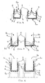
- the composite laminated article of manufacture of this invention is indicated as a whole with number 1.
- the article has an outer part providing for the sealing 2 and a core 3.
- the latter is at least partially surrounded by the outer part 2 and in practice constitutes the part of the laminated article 1 having significant mechanical resistance to traction, elasticity, rigidity and so forth.
- the core 3 is made of a material that is, on the other hand, able to undergo plastic deformation such that the core may be easily and permanently shaped from a substantially laminar original form to a channel-shaped form through a forming process that is performed to produce a channel-shaped gasket suitable to be installed onto the perimeter of a generally flat panel 1b, for example a glass pane.
- the core 3 may originally be in the form of a lamina.
- the lamina constituting the core 3 of the composite laminated article is made of metal and preferably of aluminium.
- the sealing portion 2 of the composite laminated article is of an elastic material such as an elastomer or in many case a material having an iperelastic behaviour.
- an elastic material such as an elastomer or in many case a material having an iperelastic behaviour.
- siliconic rubber or any other rubber-like material such as for example soft PVC and the like, may be employed.
- the laminated article 1 may advantageously be used for making a gasket.
- the sealing part 2 covers at least partially the core 3 and more precisely at least one of the edge or lateral portions 3b of the core, as referred to the middle or central portion 3a of the core.
- a particularly preferred embodiment of this invention contemplates that the sealing part 2 extends itself to completely envelop the core 3 like an envelope or outer coat.
- the sealing part 2 may substantially be formed as an envelope of elastomer surrounding completely the core 3.
- the metallic lamina constituting the core 3 remains completely sealed from the atmosphere and possible corrosion and/or passivation phenomena of the metallic lamina may be prevented.
- a gasket 1a may be fitted between the perimetral portion of a panel and a support frame 1c (for example a cabinet door, a shower box glass pane) may be formed.
- a support frame 1c for example a cabinet door, a shower box glass pane
- Such a gasket 1a will be composed of a core 3 which is at least partially plastically shaped such to define a channel-shaped cross section matching the edge geometry of the panel and by a sealing part 2 joined by lamination to at least a portion of the core 3.
- perimeter, perimetral portion and edge portion as referred to the panel, is intended in practice the edge of the panel which may have any cross sectional shape (for example rectangular, square, elliptical and so forth).
- the core 3 of the laminated article 1 is formed by permanent plastic deformation of the originally flat or ribbon-like article such to produce substantially a counter shape of the edge of the panel onto which the gasket 1a must be fitted.
- Appropriate dimensioning cause the sealing part of the shaped gasket formed from the laminated article to abut against surfaces of the perimetral portions of the panel contributing in a decisive manner in insuring an effective isolation between two spaces separated by the panel.
- the sealing part 2 being on the surfaces of the receiving seat of the supporting frame 1c of the panel, will prevent air and/or water infiltrations between the surfaces of the gasket and of the frame.
- the gasket 1a may even include, as shown, primary gripping means 4, that may be molded on the sealing part 2, functionally enhancing the fastening of the gasket to the edge portion of the panel on which the gasket is forcibly fitted.
- primary gripping means 4 there may be formed also secondary gripping means 5, molded on the sealing part 2 for promoting a close fitting of the gasketed perimeter of the panel in the seat of the supporting frame 1c to enhance the sealing.
- a sealing lips 6 may be formed along the edges of 3b of the core 3 for more effectively establishing a secure sealing against infiltrations of air, rain and other atmospheric agents between the edge portion of the panel and the channel-shaped gasket.
- the gripping means 4 and 5 as well as the sealing lips 6 may have different shapes, for example in form of extended teeth, parallel crests and trapezoidal shaped engrossment of the thickness of the elastomer outer layer 2. These protrusions may be formed in a simple and precise manner during an eventual co-extrusion process of the elastomer material of the sealing part 2 and of the core 3.
- the core 3 of the laminated article 1 has been shaped by plastically deforming it to define a gasket 1a
- the core 3 will have assumed a cross section that at least partially will match the shape of the cross section of the perimetral portion or edge of the panel on which the gasket must be fitted.
- the core 3 may be shaped in the form of a "C” or of a "U".
- the lateral portions 3b will, after having been bent, constitute substantially the lateral arms (parallel or divergent) of the "C” or “U” cross section, while the central portion 3a of the lamina will substantially constitute the middle portion of the "C” or of the "U” cross section (that is the portion comprised between the lateral arms).
- the invention includes also a panelling element 1b (re: Figures 8 and 9) that may be set in a supporting frame 1c (for example to compose a wall, a panel of a shower box and the like).
- a panelling element 1b comprises a pane (of any shape, for example rectangular or square) provided with a gasket 1a of the type described above disposed on at least part of its perimeter or edge 8.
- a gasket 1a may be fitted around the entire perimeter or only on part of it, for example on one or several sides of the perimetral edge 8 of the panel, according to the particular application.
- a flat ribbon-like core 3 is procured, preferably of a metal or in any case of a material suitable to be plastically deformable into a different permanent shape and to this core 3 an outer sealing layer 2 of an elastomer or of a material having a iper-elastic behaviour is associated by lamination.
- Such a sealing part 2 may be laminated over part of the core and may surround partially or entirely the core 3 which will either be partially or completely coated by the layer of sealing material 2.
- the association of the sealing part 2 to the core 3 may be made by co-extrusion.
- the core 3 is co-extruded with the extrudable material of the sealing part 2 such o be at least partially (or entirely) enveloped by the sealing material 2 thus laminated thereon.
- a gasket 1a of the type described above may be realized by an appropriate process.
- such a process consists in deforming the laminated article to shape it into a form that is practically complementary to the shape of the edge of the panel on which the gasket so-formed 1a must be fitted.
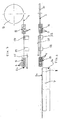
- plastic deformation of the core 3 may be preformed immediately in cascade to the co-extrusion step by arranging a series of shaping rolls 9, at the exit of the co-extrusion head properly arranged and oriented in such a way to progressively bend the laminated co-extruded article to the desired channel shape.
- the core 3 of the article 1 is eventually shaped to assume a "C" or a "U" cross sectional shape.
- a process for fabricating panelling elements 1b provided with perimetral gaskets is possible by sequentially feeding a laminated ribbon-like article 1 of the type described above along a certain direction of advancement 10, that in practice is the direction along which the fabrication line develops
- the line may include at least a station of co-extrusion and one or several gasket forming stations 11, organized in cascade of the co-extrusion station, each provided with a plurality of shaping rolls 9 arranged along the advancement direction 10.
- the perimetral gaskets are associated to a panelling element 1b by fitting the gasket 1a along the perimeter 8 of the panel (re.: figures 6 and 7). This is done by bending (by the action of the shaping rolls 9) the laminated article 1 around the edge of the panel, thus precisely conforming the gasket to the edge exploiting the ability to yield of the elastomer outer layer 2.
- the core 3 of the laminated composite 1 is plastically deformed and simultaneously the gasket 1a is fitted over the perimetral edge of the panel by passing the perimetral edge 8 of the panel and the laminated composite 1 through the forming rolls 9 such to bend the latter countershaping it around the edge of the panel itself, thus fastening the gasket thereon.
- These juxtaposed cuts have the purpose of defining segments of laminated article 1 or of pre-shaped gasket 1a, of predetermined length (for example corresponding to the length of the side of the panel on which the segments of gasket must be fitted), or even to define and prearrange zones in which the channel-shaped gasket may be bent to follow a rounded portion of the perimeter 8 of the panel.
- the invention produces important advantages.
- the characteristics of the laminated article 1 and of the gasket 1a made from it enhance sealing against air, water and/or other atmospheric agent infiltrations. This important result is achieved practically without employing glues and/or sigillant (or limiting their use to negligible quantities).
- the laminated article 1 of this invention may be readily and economically be fabricated with substantially common machines commercially available with extremely high productivity.
- the simplicity and ease of fabrication are also reflected in the process of this invention for making a gasket and even more so in the process of this invention for fabricating panelling elements already fitted with perimetral gaskets.
- the fabrication processes are all amenable to a high level of automation with evident advantages in terms of cost reduction and workmanship.
- a further advantage consists in that the laminated article of this invention by virtue of its planarity and plastic deformability characteristics may be most conveniently stored in the form of rolls rendering possible a far more efficient exploiting of logistic storage spaces, besides facilitating the distribution of the product on the market.
Landscapes
- Engineering & Computer Science (AREA)
- Civil Engineering (AREA)
- Structural Engineering (AREA)
- Electric Clocks (AREA)
- Gasket Seals (AREA)
- Laminated Bodies (AREA)
Applications Claiming Priority (2)
| Application Number | Priority Date | Filing Date | Title |
|---|---|---|---|
| ITVA20010018 ITVA20010018A1 (it) | 2001-06-19 | 2001-06-19 | Elemento laminare e guarnizione ottenibile da detto elemento laminare, nonche' procedimento per la fabbricazione di detto elemento laminare |
| ITVA20010018 | 2001-06-19 |
Publications (2)
| Publication Number | Publication Date |
|---|---|
| EP1270862A2 true EP1270862A2 (fr) | 2003-01-02 |
| EP1270862A3 EP1270862A3 (fr) | 2004-02-04 |
Family
ID=11460861
Family Applications (1)
| Application Number | Title | Priority Date | Filing Date |
|---|---|---|---|
| EP02425399A Withdrawn EP1270862A3 (fr) | 2001-06-19 | 2002-06-17 | Elément multicouche, joint fabriqué à partir de celui-ci, et son procédé de fabrication |
Country Status (2)
| Country | Link |
|---|---|
| EP (1) | EP1270862A3 (fr) |
| IT (1) | ITVA20010018A1 (fr) |
Cited By (4)
| Publication number | Priority date | Publication date | Assignee | Title |
|---|---|---|---|---|
| GB2390404B (en) * | 2002-07-06 | 2006-01-11 | Coram Showers Ltd | Gaskets |
| GB2476453A (en) * | 2009-12-15 | 2011-06-29 | Lorient Polyprod Ltd | Glazing strip |
| GB2594071A (en) * | 2020-04-15 | 2021-10-20 | Siosystems Ltd | Support system |
| US20230332459A1 (en) * | 2022-04-19 | 2023-10-19 | Coastal Industries, Inc. | Glazing beads and methods of assembly using same |
Family Cites Families (5)
| Publication number | Priority date | Publication date | Assignee | Title |
|---|---|---|---|---|
| US3167856A (en) * | 1961-11-13 | 1965-02-02 | Standard Products Co | Methods of making strip structures |
| GB1109017A (en) * | 1965-03-16 | 1968-04-10 | Charles Aubert | Improvements in or relating to the securing of structural elements |
| US3685122A (en) * | 1969-12-11 | 1972-08-22 | Ppg Industries Inc | Framing machine |
| CH522814A (de) * | 1971-03-25 | 1972-05-15 | Heglas Ag | Doppelglasscheibe mit einem gegen aussen luftdicht abgeschlossenen Innenraum, Verfahren und Vorrichtung zu deren Herstellung |
| GB8519015D0 (en) * | 1985-07-27 | 1985-09-04 | Draftex Ind Ltd | Channel-shaped strip structures reinforcements |
-
2001
- 2001-06-19 IT ITVA20010018 patent/ITVA20010018A1/it unknown
-
2002
- 2002-06-17 EP EP02425399A patent/EP1270862A3/fr not_active Withdrawn
Cited By (7)
| Publication number | Priority date | Publication date | Assignee | Title |
|---|---|---|---|---|
| GB2390404B (en) * | 2002-07-06 | 2006-01-11 | Coram Showers Ltd | Gaskets |
| GB2476453A (en) * | 2009-12-15 | 2011-06-29 | Lorient Polyprod Ltd | Glazing strip |
| GB2476453B (en) * | 2009-12-15 | 2014-07-02 | Lorient Polyprod Ltd | Glazing strip |
| GB2594071A (en) * | 2020-04-15 | 2021-10-20 | Siosystems Ltd | Support system |
| GB2594071B (en) * | 2020-04-15 | 2023-09-27 | Siosystems Ltd | Support system for panels in doors and partitions |
| US20230332459A1 (en) * | 2022-04-19 | 2023-10-19 | Coastal Industries, Inc. | Glazing beads and methods of assembly using same |
| US12098586B2 (en) * | 2022-04-19 | 2024-09-24 | Coastal Industries, Inc. | Glazing beads and methods of assembly using same |
Also Published As
| Publication number | Publication date |
|---|---|
| EP1270862A3 (fr) | 2004-02-04 |
| ITVA20010018A1 (it) | 2002-12-19 |
Similar Documents
| Publication | Publication Date | Title |
|---|---|---|
| US5579618A (en) | Composite framing member construction for windows and doors | |
| US20120324810A1 (en) | Modified glazing assembly for rough openings | |
| US4042741A (en) | Channel-shaped flexible sealing strips | |
| US3165793A (en) | Flange-gripping flexible sealingstrip carrier | |
| KR100373545B1 (ko) | 장식덮개를가진유리이동채널및벨트웨더스트립을포함하는웨더스트립조립체 | |
| US5581959A (en) | Bendable drip cap | |
| EP1333739B1 (fr) | Ensemble espaceur flexible continu equipe d'un element de support etanche | |
| US20030005651A1 (en) | Window frame system | |
| US5634306A (en) | Composite framing member construction for windows and doors | |
| US20070193140A1 (en) | Impact resistant door light | |
| US20090139165A1 (en) | Insulating glass unit | |
| US20120137608A1 (en) | Flexible wrapped insulated glass unit spacer, system and method for manufacturing same in situ and an insulated glass unit having a flexible wrapped spacer | |
| US10563453B2 (en) | Weatherstripping assemblies for garage doors and other applications, associated apparatuses, and associated methods of use | |
| GB2397311A (en) | A suspended ceiling grid beam with a seal | |
| EP0241303A2 (fr) | Joint d'étanchéité | |
| US20090139164A1 (en) | Insulating glass unit | |
| US4835031A (en) | Profiled strip with smooth reinforcing insert and method of its manufacture | |
| US20090139163A1 (en) | Insulating glass unit | |
| US20220127900A1 (en) | Spacer frame joiner clip and method of use | |
| WO2017048928A1 (fr) | Ensemble poinçon pour cadres d'espacement de fenêtres | |
| EP3679216A1 (fr) | Cadre de fenêtre à haut rendement thermique | |
| EP1270862A2 (fr) | Elément multicouche, joint fabriqué à partir de celui-ci, et son procédé de fabrication | |
| JPS5951463B2 (ja) | シ−ル帯状体およびその製作法 | |
| EP0110265A2 (fr) | Procédé pour produire en continu des panneaux multicouches autoportants stratifiés de chaque côté pourvu de flancs rigides et panneaux obtenus | |
| US3789564A (en) | Unitary rigid edge channel for windows |
Legal Events
| Date | Code | Title | Description |
|---|---|---|---|
| PUAI | Public reference made under article 153(3) epc to a published international application that has entered the european phase |
Free format text: ORIGINAL CODE: 0009012 |
|
| AK | Designated contracting states |
Kind code of ref document: A2 Designated state(s): AT BE CH CY DE DK ES FI FR GB GR IE IT LI LU MC NL PT SE TR |
|
| AX | Request for extension of the european patent |
Free format text: AL;LT;LV;MK;RO;SI |
|
| PUAL | Search report despatched |
Free format text: ORIGINAL CODE: 0009013 |
|
| AK | Designated contracting states |
Kind code of ref document: A3 Designated state(s): AT BE CH CY DE DK ES FI FR GB GR IE IT LI LU MC NL PT SE TR |
|
| AX | Request for extension of the european patent |
Extension state: AL LT LV MK RO SI |
|
| RIC1 | Information provided on ipc code assigned before grant |
Ipc: 7B 60J 10/00 B Ipc: 7E 06B 3/62 A |
|
| 17P | Request for examination filed |
Effective date: 20040804 |
|
| AKX | Designation fees paid |
Designated state(s): AT BE CH CY DE DK ES FI FR GB GR IE IT LI LU MC NL PT SE TR |
|
| 17Q | First examination report despatched |
Effective date: 20050124 |
|
| STAA | Information on the status of an ep patent application or granted ep patent |
Free format text: STATUS: THE APPLICATION HAS BEEN WITHDRAWN |
|
| 18W | Application withdrawn |
Effective date: 20050528 |