EP1270880A1 - Deckplatte einer Brennkraftmaschine mit integrierten Kontrollelementen von Drehwinkelverstellvorrichtungen - Google Patents
Deckplatte einer Brennkraftmaschine mit integrierten Kontrollelementen von Drehwinkelverstellvorrichtungen Download PDFInfo
- Publication number
- EP1270880A1 EP1270880A1 EP02254360A EP02254360A EP1270880A1 EP 1270880 A1 EP1270880 A1 EP 1270880A1 EP 02254360 A EP02254360 A EP 02254360A EP 02254360 A EP02254360 A EP 02254360A EP 1270880 A1 EP1270880 A1 EP 1270880A1
- Authority
- EP
- European Patent Office
- Prior art keywords
- engine
- cover
- cam phaser
- cam
- variable
- Prior art date
- Legal status (The legal status is an assumption and is not a legal conclusion. Google has not performed a legal analysis and makes no representation as to the accuracy of the status listed.)
- Granted
Links
- RDYMFSUJUZBWLH-UHFFFAOYSA-N endosulfan Chemical compound C12COS(=O)OCC2C2(Cl)C(Cl)=C(Cl)C1(Cl)C2(Cl)Cl RDYMFSUJUZBWLH-UHFFFAOYSA-N 0.000 claims abstract description 32
- 238000002485 combustion reaction Methods 0.000 claims abstract description 6
- 230000005540 biological transmission Effects 0.000 claims description 3
- 230000009977 dual effect Effects 0.000 claims description 3
- 230000008878 coupling Effects 0.000 claims 1
- 238000010168 coupling process Methods 0.000 claims 1
- 238000005859 coupling reaction Methods 0.000 claims 1
- 239000004020 conductor Substances 0.000 description 2
- 238000006073 displacement reaction Methods 0.000 description 2
- 239000012530 fluid Substances 0.000 description 2
- 238000004519 manufacturing process Methods 0.000 description 2
- 238000007796 conventional method Methods 0.000 description 1
- 238000005260 corrosion Methods 0.000 description 1
- 230000007797 corrosion Effects 0.000 description 1
- 239000000835 fiber Substances 0.000 description 1
- 239000000446 fuel Substances 0.000 description 1
- 238000010348 incorporation Methods 0.000 description 1
- 230000010354 integration Effects 0.000 description 1
- 201000002266 mite infestation Diseases 0.000 description 1
Images
Classifications
-
- F—MECHANICAL ENGINEERING; LIGHTING; HEATING; WEAPONS; BLASTING
- F02—COMBUSTION ENGINES; HOT-GAS OR COMBUSTION-PRODUCT ENGINE PLANTS
- F02F—CYLINDERS, PISTONS OR CASINGS, FOR COMBUSTION ENGINES; ARRANGEMENTS OF SEALINGS IN COMBUSTION ENGINES
- F02F7/00—Casings, e.g. crankcases
- F02F7/006—Camshaft or pushrod housings
-
- F—MECHANICAL ENGINEERING; LIGHTING; HEATING; WEAPONS; BLASTING
- F01—MACHINES OR ENGINES IN GENERAL; ENGINE PLANTS IN GENERAL; STEAM ENGINES
- F01L—CYCLICALLY OPERATING VALVES FOR MACHINES OR ENGINES
- F01L1/00—Valve-gear or valve arrangements, e.g. lift-valve gear
- F01L1/02—Valve drive
-
- F—MECHANICAL ENGINEERING; LIGHTING; HEATING; WEAPONS; BLASTING
- F01—MACHINES OR ENGINES IN GENERAL; ENGINE PLANTS IN GENERAL; STEAM ENGINES
- F01L—CYCLICALLY OPERATING VALVES FOR MACHINES OR ENGINES
- F01L1/00—Valve-gear or valve arrangements, e.g. lift-valve gear
- F01L1/02—Valve drive
- F01L1/024—Belt drive
-
- F—MECHANICAL ENGINEERING; LIGHTING; HEATING; WEAPONS; BLASTING
- F01—MACHINES OR ENGINES IN GENERAL; ENGINE PLANTS IN GENERAL; STEAM ENGINES
- F01L—CYCLICALLY OPERATING VALVES FOR MACHINES OR ENGINES
- F01L1/00—Valve-gear or valve arrangements, e.g. lift-valve gear
- F01L1/02—Valve drive
- F01L1/04—Valve drive by means of cams, camshafts, cam discs, eccentrics or the like
- F01L1/047—Camshafts
- F01L1/053—Camshafts overhead type
-
- F—MECHANICAL ENGINEERING; LIGHTING; HEATING; WEAPONS; BLASTING
- F01—MACHINES OR ENGINES IN GENERAL; ENGINE PLANTS IN GENERAL; STEAM ENGINES
- F01L—CYCLICALLY OPERATING VALVES FOR MACHINES OR ENGINES
- F01L1/00—Valve-gear or valve arrangements, e.g. lift-valve gear
- F01L1/34—Valve-gear or valve arrangements, e.g. lift-valve gear characterised by the provision of means for changing the timing of the valves without changing the duration of opening and without affecting the magnitude of the valve lift
-
- F—MECHANICAL ENGINEERING; LIGHTING; HEATING; WEAPONS; BLASTING
- F02—COMBUSTION ENGINES; HOT-GAS OR COMBUSTION-PRODUCT ENGINE PLANTS
- F02B—INTERNAL-COMBUSTION PISTON ENGINES; COMBUSTION ENGINES IN GENERAL
- F02B75/00—Other engines
- F02B75/16—Engines characterised by number of cylinders, e.g. single-cylinder engines
- F02B75/18—Multi-cylinder engines
- F02B75/22—Multi-cylinder engines with cylinders in V, fan, or star arrangement
-
- F—MECHANICAL ENGINEERING; LIGHTING; HEATING; WEAPONS; BLASTING
- F02—COMBUSTION ENGINES; HOT-GAS OR COMBUSTION-PRODUCT ENGINE PLANTS
- F02F—CYLINDERS, PISTONS OR CASINGS, FOR COMBUSTION ENGINES; ARRANGEMENTS OF SEALINGS IN COMBUSTION ENGINES
- F02F7/00—Casings, e.g. crankcases
- F02F7/0002—Cylinder arrangements
- F02F7/0012—Crankcases of V-engines
-
- F—MECHANICAL ENGINEERING; LIGHTING; HEATING; WEAPONS; BLASTING
- F02—COMBUSTION ENGINES; HOT-GAS OR COMBUSTION-PRODUCT ENGINE PLANTS
- F02F—CYLINDERS, PISTONS OR CASINGS, FOR COMBUSTION ENGINES; ARRANGEMENTS OF SEALINGS IN COMBUSTION ENGINES
- F02F7/00—Casings, e.g. crankcases
- F02F7/0065—Shape of casings for other machine parts and purposes, e.g. utilisation purposes, safety
- F02F7/0073—Adaptations for fitting the engine, e.g. front-plates or bell-housings
-
- F—MECHANICAL ENGINEERING; LIGHTING; HEATING; WEAPONS; BLASTING
- F01—MACHINES OR ENGINES IN GENERAL; ENGINE PLANTS IN GENERAL; STEAM ENGINES
- F01L—CYCLICALLY OPERATING VALVES FOR MACHINES OR ENGINES
- F01L1/00—Valve-gear or valve arrangements, e.g. lift-valve gear
- F01L1/02—Valve drive
- F01L1/04—Valve drive by means of cams, camshafts, cam discs, eccentrics or the like
- F01L1/047—Camshafts
- F01L1/053—Camshafts overhead type
- F01L2001/0537—Double overhead camshafts [DOHC]
-
- F—MECHANICAL ENGINEERING; LIGHTING; HEATING; WEAPONS; BLASTING
- F01—MACHINES OR ENGINES IN GENERAL; ENGINE PLANTS IN GENERAL; STEAM ENGINES
- F01L—CYCLICALLY OPERATING VALVES FOR MACHINES OR ENGINES
- F01L1/00—Valve-gear or valve arrangements, e.g. lift-valve gear
- F01L1/34—Valve-gear or valve arrangements, e.g. lift-valve gear characterised by the provision of means for changing the timing of the valves without changing the duration of opening and without affecting the magnitude of the valve lift
- F01L1/344—Valve-gear or valve arrangements, e.g. lift-valve gear characterised by the provision of means for changing the timing of the valves without changing the duration of opening and without affecting the magnitude of the valve lift changing the angular relationship between crankshaft and camshaft, e.g. using helicoidal gear
- F01L1/3442—Valve-gear or valve arrangements, e.g. lift-valve gear characterised by the provision of means for changing the timing of the valves without changing the duration of opening and without affecting the magnitude of the valve lift changing the angular relationship between crankshaft and camshaft, e.g. using helicoidal gear using hydraulic chambers with variable volume to transmit the rotating force
- F01L2001/34423—Details relating to the hydraulic feeding circuit
- F01L2001/34426—Oil control valves
- F01L2001/3443—Solenoid driven oil control valves
-
- F—MECHANICAL ENGINEERING; LIGHTING; HEATING; WEAPONS; BLASTING
- F02—COMBUSTION ENGINES; HOT-GAS OR COMBUSTION-PRODUCT ENGINE PLANTS
- F02B—INTERNAL-COMBUSTION PISTON ENGINES; COMBUSTION ENGINES IN GENERAL
- F02B2275/00—Other engines, components or details, not provided for in other groups of this subclass
- F02B2275/18—DOHC [Double overhead camshaft]
Definitions
- the invention pertains to the field of internal combustion engines. More particularly, the invention pertains to the integration of variable cam timing controls into the engine's front cover.
- VCT variable cam timing
- active noise cancellation the angular displacement, or phase of a camshaft, relative to the crankshaft to which it is drivably connected, is dynamically altered to bring about changes in engine characteristics, such as fuel economy or power.
- engine characteristics such as fuel economy or power.
- feedback loop in which the desired values of such engine characteristics are measured against their existing values, and changes are effected inside the engine in response to discrepancies.
- control module or more than one
- a microcomputer that constantly analyzes data fed into it from various parts of the engine and other parts of the automobile and ambient conditions (exhaust gas sensors, pressure and temperature sensors, etc.) and emits signals in response to such data.
- VCT angular displacement between the cam shaft and the crank shaft that drives it is altered.
- the conventional method of connecting a system, such as a VCT system, to the control module is to run a set of wires from each solenoid, valve, actuator or motor and each sensor back to the engine controller.
- a system such as a VCT system
- the number of wires feeding into the engine controller has recently become unmanageable.
- some engine controllers now have upwards of 150 to 200 externally-connected wires.
- U.S. Patent No. 5,353,755 to Matsuo et al discloses a variable valve timing control system incorporated into the front cover of a V-type internal combustion engine.
- the patent teaches a V-type engine comprising a plurality of hydraulically actuated valve operation mode control actuators for two cylinder banks.
- a hydraulic fluid network is fluidly disposed between a main gallery of the cylinder block and the plurality of hydraulically actuable valve operation mode control actuators, and includes a single control valve, which is common to all of the hydraulically actuable valve operation mode control actuators.
- This control valve is attached to a casing adapted to receive a drive system connecting the engine camshafts to the engine crankshaft.
- the casing also has internal passages forming a part of the hydraulic fluid network between the control valve and the plurality of hydraulically actuable valve operation mode control actuators.
- front cover refers to the cover over the timing components of the engine - the camshaft drive element(s) (gear, sprocket or pulley) and cam phaser(s), the crankshaft end and drive element (gear, sprocket or pulley), and the power transmission component (chain, belt or gears) connecting the crankshaft drive to the cam drive(s).
- this cover would usually be toward the front of the engine (hence the term, "front cover"), but it will be understood that in other engine mounting schemes it might be toward the side of the car (as in a transverse engine) or facing the rear.
- a front cover for an internal combustion engine comprises variable cam timing (VCT) controls integrated into the cover, including variable force solenoids (VFS) and cam (and possibly crankshaft) position sensors, the cover being located in front of and operably connected to a cam phaser.
- VCT control module also mounted on the cover, communicates with the actuators and sensors, and provides the connection to the car's control module, thus limiting the number of external conductors necessary to interface with the VCT system.
- the engine cover once assembled, comprises a single unit having an electronic interface module (EIM), VFS and position sensor integrated within said cover. This invention allows the cam position sensor to sense the cam position from a wheel mounted in front of the cam phaser, rather than from a pulse wheel mounted on the cam.
- EIM electronic interface module
- the typical cam phaser system includes a position sensor wheel on the cam, which sends a signal back to the engine controller.
- the inventors of the present invention have found that by moving both the control solenoid and the cam position sensor for each cam to the front of the cam phaser, the solenoid and cam position sensors can be mounted in the front cover. This invention allows the cam position sensor to sense the cam position from a wheel mounted in front of the cam phaser, rather than from a pulse wheel mounted on the cam.
- the EIM 40 is mounted to the front cover 100.
- a controller area network (CAN) bus input to the electronic interface module (EIM) 40 also preferably is included, which allows the control system of the present invention to receive set point commands from the engine control module (ECM).
- the CAN bus input can be in any form convenient to the engine design, for example a one or more pairs of wires, fiber optics, etc.
- the VCT control system of the present invention preferably includes a crank position sensor 60 mounted to the engine front cover 100.
- the crank position sensor could be mounted on the front of the engine, instead, or the crank position sensed in some other way, but that would necessitate additional conductors to convey the crank position information to the EIM.
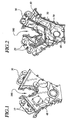
- Each cam location on an engine has a cam bank 30 with connections for receiving a phaser actuator 10 (in figs. 1-2, a variable force solenoid (VFS)) and a cam position sensor 20 for each cam at the location.
- a phaser actuator 10 in figs. 1-2, a variable force solenoid (VFS)
- VFS variable force solenoid
- cam position sensor 20 for each cam at the location.
- V type dual overhead cam embodiment of figs. 1-2
- there are four VFS 10 and four cam sensors 20 in two banks 30 there are four VFS 10 and four cam sensors 20 in two banks 30.
- the cover of the invention can be applied to other types of engines as well: a single cam four-cylinder engine would have only one cam bank with one actuator and one sensor, a single camshaft “V" or horizontally opposed type engine would have two banks, each with one actuator and one sensor, and a dual cam inline-type engine would have one bank with two actuators and two sensors.
- the EIM 40 is preferably mounted into a recess and plugs into an interconnect harness 50 that connects the each cam bank to the EIM.
- the interconnect harness 50 is mounted inside the cover, so that the terminals do not have to be exposed to the elements inside the engine compartment.
- the harness is molded to follow the contour of the inside of the cover.
- the front cover 100 comprises a single unit with the EIM 40, VFS 10 and cam position sensors 20 being integrated into the unit.
- Other features optionally are added to the front cover, such as, for example, active noise reduction 70.
- the control system of the present invention reduces the overall cost of the variable cam timing system, by eliminating more than twenty wires to the engine controller.
- the only connections to the engine compartment that are required are power (supply voltage and ground), the CAN bus, and optionally a buffered crank signal for the engine controller.
- the overall engine control system is simplified by the use of the invention, as the ECM needs only to calculate a desired cam timing and supply a VCT set point signal to the assembly of the invention, rather than having to read cam and crank sensor signals, compute present cam positions and desired cam offsets and drive each VFS separately.
- Moving the cam timing control to the valve cover also simplifies design and production by allowing the ECM designer to ignore variations and production changes in cam sensors and actuators, as the EIM handles the actual interfacing with the VCT components.
- each wire and connector can be as much as $1 per wire.
- the cost of assembly at the engine plant is reduced, because the front cover module, which contains all the actuators and sensors, can be assembled as a unit, rather then individually as separate parts.
- Overall reliability is increased, as each wire eliminated also eliminates a potential source of corrosion, noise, trouble and expense for the car owner and the dealer.
Landscapes
- Engineering & Computer Science (AREA)
- Mechanical Engineering (AREA)
- General Engineering & Computer Science (AREA)
- Chemical & Material Sciences (AREA)
- Combustion & Propulsion (AREA)
- Valve Device For Special Equipments (AREA)
- Valve-Gear Or Valve Arrangements (AREA)
- Cylinder Crankcases Of Internal Combustion Engines (AREA)
Applications Claiming Priority (2)
| Application Number | Priority Date | Filing Date | Title |
|---|---|---|---|
| US09/886,736 US6435154B1 (en) | 2001-06-21 | 2001-06-21 | VCT controls integrated into front cover of engine |
| US886736 | 2001-06-21 |
Publications (2)
| Publication Number | Publication Date |
|---|---|
| EP1270880A1 true EP1270880A1 (de) | 2003-01-02 |
| EP1270880B1 EP1270880B1 (de) | 2004-03-24 |
Family
ID=25389654
Family Applications (1)
| Application Number | Title | Priority Date | Filing Date |
|---|---|---|---|
| EP02254360A Expired - Lifetime EP1270880B1 (de) | 2001-06-21 | 2002-06-21 | Deckplatte einer Brennkraftmaschine mit integrierten Kontrollelementen von Drehwinkelverstellvorrichtungen |
Country Status (4)
| Country | Link |
|---|---|
| US (1) | US6435154B1 (de) |
| EP (1) | EP1270880B1 (de) |
| JP (1) | JP4130878B2 (de) |
| DE (1) | DE60200283T2 (de) |
Families Citing this family (19)
| Publication number | Priority date | Publication date | Assignee | Title |
|---|---|---|---|---|
| DE10148059A1 (de) * | 2001-09-28 | 2003-04-17 | Daimler Chrysler Ag | Nockenwellenverstellvorrichtung für eine Brennkraftmaschine |
| EP1310634A3 (de) * | 2001-11-07 | 2007-07-25 | Valeo Schalter und Sensoren GmbH | Magnetsteller für einen Nockenwellenversteller |
| US6571757B1 (en) * | 2002-04-22 | 2003-06-03 | Borgwarner Inc. | Variable force solenoid with spool position feedback to control the position of a center mounted spool valve to control the phase angle of cam mounted phaser |
| DE10231917A1 (de) | 2002-07-15 | 2004-01-29 | Daimlerchrysler Ag | Vorrichtung mit wenigstens einer Funktionseinheit einer Nockenwellenverstellvorrichtung |
| US6837207B2 (en) | 2002-07-18 | 2005-01-04 | Kohler Co. | Inverted crankcase with attachments for an internal combustion engine |
| US6904880B2 (en) * | 2003-10-06 | 2005-06-14 | Borgwarner Inc. | VCT sensor and actuator module |
| US7334555B2 (en) * | 2004-02-02 | 2008-02-26 | Freudenberg-Nok General Partnership | Stamped crankshaft seal retainer plate and molded encoder sensor support feature |
| JP4321504B2 (ja) * | 2005-07-25 | 2009-08-26 | 日産自動車株式会社 | 内燃機関のカム角センサ取付構造 |
| DE112006002816T5 (de) | 2005-11-28 | 2008-10-02 | Borgwarner Inc., Auburn Hills | VCT-Steuermodul mit Intelligenz |
| DE102006016650B4 (de) | 2006-04-08 | 2019-05-16 | Schaeffler Technologies AG & Co. KG | Nockenwellentrieb für eine Brennkraftmaschine |
| CN101506478A (zh) * | 2006-08-25 | 2009-08-12 | 博格华纳公司 | 带有一体化的位置传感器的可变力螺线管 |
| US7341038B1 (en) | 2006-12-15 | 2008-03-11 | Federal - Mogul World Wide, Inc. | Engine cover with embedded leads |
| WO2009009328A1 (en) * | 2007-07-06 | 2009-01-15 | Borgwarner Inc. | Variable cam timing controls mounted in the camshaft |
| JP2011127432A (ja) * | 2009-12-15 | 2011-06-30 | Hitachi Automotive Systems Ltd | バルブタイミング制御装置用カバー及びその製造方法 |
| JP5435279B2 (ja) * | 2010-02-15 | 2014-03-05 | スズキ株式会社 | 可変バルブタイミング機構付エンジン |
| CN101975096B (zh) * | 2010-10-20 | 2014-04-02 | 奇瑞汽车股份有限公司 | 一种发动机凸轮轴第一轴承盖 |
| CA2940506C (en) * | 2015-08-28 | 2020-12-29 | Paul Gregory De Boer | Sensing unit providing fixed arrangement of engine position sensors |
| USD950606S1 (en) * | 2019-11-19 | 2022-05-03 | Transportation Ip Holdings, Llc | Forward end housing |
| USD975137S1 (en) * | 2022-03-21 | 2023-01-10 | Njr Enterprises Llc | Front cover for an engine |
Citations (5)
| Publication number | Priority date | Publication date | Assignee | Title |
|---|---|---|---|---|
| EP0704605A2 (de) * | 1994-09-30 | 1996-04-03 | Yamaha Hatsudoki Kabushiki Kaisha | Brennkraftmaschine mit Vorrichtung zur Verstellung der Nockenphase |
| JPH0968053A (ja) * | 1995-08-31 | 1997-03-11 | Suzuki Motor Corp | 内燃機関用センサ取付構造 |
| US6050236A (en) * | 1997-05-28 | 2000-04-18 | Nissan Motor Co., Ltd. | Covering device for an internal combustion engine |
| US6182624B1 (en) * | 1998-12-29 | 2001-02-06 | Suzuki Motor Corporation | Hydraulic control valve mounting structure in an engine |
| US6247436B1 (en) * | 1997-09-27 | 2001-06-19 | Mechadyne Plc | Engine front cover |
Family Cites Families (8)
| Publication number | Priority date | Publication date | Assignee | Title |
|---|---|---|---|---|
| SE452639B (sv) * | 1984-12-20 | 1987-12-07 | Saab Scania Ab | Arrangemang vid en forbrenningsmotor for anslutning av en legesavkennande givare |
| DE3810804A1 (de) | 1988-03-30 | 1989-10-19 | Daimler Benz Ag | Vorrichtung zur relativen winkelverstellung zwischen zwei in antriebsverbindung stehenden wellen |
| US5497738A (en) | 1992-09-03 | 1996-03-12 | Borg-Warner Automotive, Inc. | VCT control with a direct electromechanical actuator |
| US5218935A (en) | 1992-09-03 | 1993-06-15 | Borg-Warner Automotive Transmission & Engine Components Corporation | VCT system having closed loop control employing spool valve actuated by a stepper motor |
| JP2891013B2 (ja) | 1993-01-18 | 1999-05-17 | 日産自動車株式会社 | V型内燃機関における可変バルブタイミングコントロール装置 |
| US6178939B1 (en) * | 1998-06-24 | 2001-01-30 | Siemens Canada Limited | Housing system |
| US6293244B1 (en) * | 2000-05-09 | 2001-09-25 | Ford Global Technologies, Inc. | Oil flow control system for engine cylinder head |
| JP2001329885A (ja) * | 2000-05-18 | 2001-11-30 | Yamaha Motor Co Ltd | エンジンのカム角センサ搭載構造 |
-
2001
- 2001-06-21 US US09/886,736 patent/US6435154B1/en not_active Expired - Fee Related
-
2002
- 2002-06-20 JP JP2002179821A patent/JP4130878B2/ja not_active Expired - Fee Related
- 2002-06-21 EP EP02254360A patent/EP1270880B1/de not_active Expired - Lifetime
- 2002-06-21 DE DE60200283T patent/DE60200283T2/de not_active Expired - Fee Related
Patent Citations (5)
| Publication number | Priority date | Publication date | Assignee | Title |
|---|---|---|---|---|
| EP0704605A2 (de) * | 1994-09-30 | 1996-04-03 | Yamaha Hatsudoki Kabushiki Kaisha | Brennkraftmaschine mit Vorrichtung zur Verstellung der Nockenphase |
| JPH0968053A (ja) * | 1995-08-31 | 1997-03-11 | Suzuki Motor Corp | 内燃機関用センサ取付構造 |
| US6050236A (en) * | 1997-05-28 | 2000-04-18 | Nissan Motor Co., Ltd. | Covering device for an internal combustion engine |
| US6247436B1 (en) * | 1997-09-27 | 2001-06-19 | Mechadyne Plc | Engine front cover |
| US6182624B1 (en) * | 1998-12-29 | 2001-02-06 | Suzuki Motor Corporation | Hydraulic control valve mounting structure in an engine |
Non-Patent Citations (1)
| Title |
|---|
| PATENT ABSTRACTS OF JAPAN vol. 1997, no. 07 31 July 1997 (1997-07-31) * |
Also Published As
| Publication number | Publication date |
|---|---|
| JP4130878B2 (ja) | 2008-08-06 |
| JP2003049707A (ja) | 2003-02-21 |
| DE60200283D1 (de) | 2004-04-29 |
| US6435154B1 (en) | 2002-08-20 |
| DE60200283T2 (de) | 2004-08-12 |
| EP1270880B1 (de) | 2004-03-24 |
Similar Documents
| Publication | Publication Date | Title |
|---|---|---|
| EP1270880B1 (de) | Deckplatte einer Brennkraftmaschine mit integrierten Kontrollelementen von Drehwinkelverstellvorrichtungen | |
| US7040265B2 (en) | Multiple displacement system for an engine | |
| EP0607139B1 (de) | Hydraulisch betaetiges brennstoffeinspritzsystem mit helmholz-resonator steuervorrichtung | |
| US6138641A (en) | Fuel injection device for auto-ignition internal combustion engines | |
| US20070113812A1 (en) | Cylinder head cover | |
| JPH09317556A (ja) | シリンダヘッドカバー | |
| US20040168659A1 (en) | Variable valve operating system for internal combustion engine | |
| US7784438B2 (en) | Mounting module of oil control valve for tappet control in cylinder deactivation engine | |
| US6314946B1 (en) | Fuel injection system for diesel engines | |
| JP3733743B2 (ja) | 内燃機関のオイル通路構造 | |
| EP0393249B1 (de) | Lufteinlasssystem für eine Mehrzylinderbrennkraftmaschine | |
| US20040244751A1 (en) | Deactivating valve lifter | |
| US5875754A (en) | Internal combustion engine cylinder head arrangement | |
| US6561153B2 (en) | Cylinder head spark plug mounting arrangement | |
| JPH06501088A (ja) | 内燃機関における燃料導管用装置 | |
| US6293244B1 (en) | Oil flow control system for engine cylinder head | |
| US6182625B1 (en) | Oil-passage structure of internal combustion engine | |
| US6904880B2 (en) | VCT sensor and actuator module | |
| US6295964B1 (en) | End-feed variable cam timing oil supply and control module | |
| US11009144B2 (en) | Solenoid control valve | |
| KR101189087B1 (ko) | 엔진, 및 실린더 헤드용 캠샤프트 커버 | |
| US8116964B2 (en) | Method for the individual control of a set of valve actuators by the ECU | |
| CN101316987A (zh) | 可变凸轮正时控制模块和控制方法 | |
| EP1243760A2 (de) | Brennkraftmaschine | |
| JP3633088B2 (ja) | エンジンの補機取付構造 |
Legal Events
| Date | Code | Title | Description |
|---|---|---|---|
| PUAI | Public reference made under article 153(3) epc to a published international application that has entered the european phase |
Free format text: ORIGINAL CODE: 0009012 |
|
| AK | Designated contracting states |
Kind code of ref document: A1 Designated state(s): AT BE CH CY DE DK ES FI FR GB GR IE IT LI LU MC NL PT SE TR |
|
| AX | Request for extension of the european patent |
Free format text: AL;LT;LV;MK;RO;SI |
|
| GRAH | Despatch of communication of intention to grant a patent |
Free format text: ORIGINAL CODE: EPIDOS IGRA |
|
| 17P | Request for examination filed |
Effective date: 20030211 |
|
| GRAS | Grant fee paid |
Free format text: ORIGINAL CODE: EPIDOSNIGR3 |
|
| RAP1 | Party data changed (applicant data changed or rights of an application transferred) |
Owner name: BORGWARNER INC. |
|
| AKX | Designation fees paid |
Designated state(s): DE FR GB IT |
|
| GRAA | (expected) grant |
Free format text: ORIGINAL CODE: 0009210 |
|
| AK | Designated contracting states |
Kind code of ref document: B1 Designated state(s): DE FR GB IT |
|
| REG | Reference to a national code |
Ref country code: GB Ref legal event code: FG4D |
|
| REG | Reference to a national code |
Ref country code: IE Ref legal event code: FG4D |
|
| REF | Corresponds to: |
Ref document number: 60200283 Country of ref document: DE Date of ref document: 20040429 Kind code of ref document: P |
|
| ET | Fr: translation filed | ||
| PLBE | No opposition filed within time limit |
Free format text: ORIGINAL CODE: 0009261 |
|
| STAA | Information on the status of an ep patent application or granted ep patent |
Free format text: STATUS: NO OPPOSITION FILED WITHIN TIME LIMIT |
|
| 26N | No opposition filed |
Effective date: 20041228 |
|
| REG | Reference to a national code |
Ref country code: IE Ref legal event code: MM4A |
|
| PGFP | Annual fee paid to national office [announced via postgrant information from national office to epo] |
Ref country code: GB Payment date: 20070511 Year of fee payment: 6 |
|
| PGFP | Annual fee paid to national office [announced via postgrant information from national office to epo] |
Ref country code: IT Payment date: 20080617 Year of fee payment: 7 |
|
| PGFP | Annual fee paid to national office [announced via postgrant information from national office to epo] |
Ref country code: DE Payment date: 20080630 Year of fee payment: 7 |
|
| GBPC | Gb: european patent ceased through non-payment of renewal fee |
Effective date: 20080621 |
|
| PG25 | Lapsed in a contracting state [announced via postgrant information from national office to epo] |
Ref country code: GB Free format text: LAPSE BECAUSE OF NON-PAYMENT OF DUE FEES Effective date: 20080621 |
|
| REG | Reference to a national code |
Ref country code: FR Ref legal event code: ST Effective date: 20100226 |
|
| PG25 | Lapsed in a contracting state [announced via postgrant information from national office to epo] |
Ref country code: FR Free format text: LAPSE BECAUSE OF NON-PAYMENT OF DUE FEES Effective date: 20090630 |
|
| PGFP | Annual fee paid to national office [announced via postgrant information from national office to epo] |
Ref country code: FR Payment date: 20080424 Year of fee payment: 7 |
|
| PG25 | Lapsed in a contracting state [announced via postgrant information from national office to epo] |
Ref country code: DE Free format text: LAPSE BECAUSE OF NON-PAYMENT OF DUE FEES Effective date: 20100101 |
|
| PG25 | Lapsed in a contracting state [announced via postgrant information from national office to epo] |
Ref country code: IT Free format text: LAPSE BECAUSE OF NON-PAYMENT OF DUE FEES Effective date: 20090621 |