EP1270942A2 - Palier de poussée pour le plateau en biais d'un compresseur - Google Patents
Palier de poussée pour le plateau en biais d'un compresseur Download PDFInfo
- Publication number
- EP1270942A2 EP1270942A2 EP01308171A EP01308171A EP1270942A2 EP 1270942 A2 EP1270942 A2 EP 1270942A2 EP 01308171 A EP01308171 A EP 01308171A EP 01308171 A EP01308171 A EP 01308171A EP 1270942 A2 EP1270942 A2 EP 1270942A2
- Authority
- EP
- European Patent Office
- Prior art keywords
- race
- driving shaft
- thrust bearing
- outer diameter
- stationary
- Prior art date
- Legal status (The legal status is an assumption and is not a legal conclusion. Google has not performed a legal analysis and makes no representation as to the accuracy of the status listed.)
- Granted
Links
Images


Classifications
-
- F—MECHANICAL ENGINEERING; LIGHTING; HEATING; WEAPONS; BLASTING
- F04—POSITIVE - DISPLACEMENT MACHINES FOR LIQUIDS; PUMPS FOR LIQUIDS OR ELASTIC FLUIDS
- F04B—POSITIVE-DISPLACEMENT MACHINES FOR LIQUIDS; PUMPS
- F04B27/00—Multi-cylinder pumps specially adapted for elastic fluids and characterised by number or arrangement of cylinders
- F04B27/08—Multi-cylinder pumps specially adapted for elastic fluids and characterised by number or arrangement of cylinders having cylinders coaxial with, or parallel or inclined to, main shaft axis
- F04B27/10—Multi-cylinder pumps specially adapted for elastic fluids and characterised by number or arrangement of cylinders having cylinders coaxial with, or parallel or inclined to, main shaft axis having stationary cylinders
- F04B27/1036—Component parts, details, e.g. sealings, lubrication
- F04B27/1054—Actuating elements
- F04B27/1063—Actuating-element bearing means or driving-axis bearing means
-
- F—MECHANICAL ENGINEERING; LIGHTING; HEATING; WEAPONS; BLASTING
- F16—ENGINEERING ELEMENTS AND UNITS; GENERAL MEASURES FOR PRODUCING AND MAINTAINING EFFECTIVE FUNCTIONING OF MACHINES OR INSTALLATIONS; THERMAL INSULATION IN GENERAL
- F16C—SHAFTS; FLEXIBLE SHAFTS; ELEMENTS OR CRANKSHAFT MECHANISMS; ROTARY BODIES OTHER THAN GEARING ELEMENTS; BEARINGS
- F16C19/00—Bearings with rolling contact, for exclusively rotary movement
- F16C19/22—Bearings with rolling contact, for exclusively rotary movement with bearing rollers essentially of the same size in one or more circular rows, e.g. needle bearings
- F16C19/30—Bearings with rolling contact, for exclusively rotary movement with bearing rollers essentially of the same size in one or more circular rows, e.g. needle bearings for axial load mainly
-
- F—MECHANICAL ENGINEERING; LIGHTING; HEATING; WEAPONS; BLASTING
- F16—ENGINEERING ELEMENTS AND UNITS; GENERAL MEASURES FOR PRODUCING AND MAINTAINING EFFECTIVE FUNCTIONING OF MACHINES OR INSTALLATIONS; THERMAL INSULATION IN GENERAL
- F16C—SHAFTS; FLEXIBLE SHAFTS; ELEMENTS OR CRANKSHAFT MECHANISMS; ROTARY BODIES OTHER THAN GEARING ELEMENTS; BEARINGS
- F16C27/00—Elastic or yielding bearings or bearing supports, for exclusively rotary movement
- F16C27/08—Elastic or yielding bearings or bearing supports, for exclusively rotary movement primarily for axial load, e.g. for vertically-arranged shafts
Definitions
- the present invention relates to a thrust bearing assembly for supporting a drive shaft with respect to a housing and to a compressor, such as a variable displacement swash plate type compressor for use in an air conditioner of an automobile.
- variable displacement swash plate type compressors are used for controlling an amount of a fluid to be ejected by increasing or decreasing a piston stroke depending on an inclination angle of a swash plate.
- variable displacement swash plate type compressor 1 comprises a cylinder block 2 including a center bore 4 and a plurality of cylinder bores 6 radially formed around the center bore 4, the sides of the cylinder block 2 being hermetically covered with respectively a front housing 8 and a rear housing 10. Between the cylinder block 2 and the front housing 8, an airtight crank chamber 12 is formed, and between the back end of the cylinder block 2 and the rear housing 10, a valve plate 14 is interposed. Further, the rear housing 10 is provided with an inlet and an outlet for a refrigerating gas, a suction chamber 16 and a discharge chamber 18.
- a driving shaft 20 is installed at a central portion of the compressor 1, the driving shaft extending through the front housing 8 into the cylinder block 2. Further, the driving shaft 20 is rotatably supported by radial bearings 22 which are installed at the front housing 8 and the cylinder block 2, and one end thereof is axially supported by a support to prevent the driving shaft 2 from moving the axial direction.
- the cylinder block 2 is coupled to the front and the rear housings 8 and 10 by a through bolt 24.
- a rotor 26 is fixedly mounted around the driving shaft 20 extending across the crank chamber 12 in such a manner that the rotor 26 rotates together with the driving shaft 20.
- a swash plate 28 is rotatably installed around the driving shaft 20. Further, between the driving shaft 20 and the swash plate 28 a spherical sleeve may be interposed. In this case, the swash plate 28 is rotatably supported by an outer surface of the spherical sleeve. In Fig. 1, the swash plate 28 is positioned at a maximum angle of inclination.
- a stop surface 32a of a protuberance 32 of the swash plate 28 comes into contact with the rotor 26 and a spring 30 is compressed in the maximum state. Therefore, the rotor 26 confines a maximal angle of inclination of the swash plate. Further, the driving shaft 20 is provided with a stopper 34 for defining the minimum angle of the inclination of the swash plate 28.
- swash plate 28 and the rotor 26 are connected with each other through a hinge mechanism so that they rotate together.
- a support arm 36 protrudes outwardly from one side of the rotor 26 in the axial direction of the driving shaft 20, and an arm 38 extends from one side of the swash plate 28 to the support arm 36.
- the arms 36 and 38 are connected to each other through a pin 40.
- a piston is slidably disposed in each of the cylinder bores 6, each of the pistons having a body 44 and a bridge 46, the body being slidably installed in the cylinder bore 6.
- the bridge 46 of the piston has a recess 48 in which a portion of the outer periphery of the swash plate is positioned.
- Hemispherical shoes 50 are disposed in a shoe pocket 52 formed in the bridge 46 of the piston, and slidably engaged with both sides of the outer peripheral portion of the swash plate 28. Consequently, during the rotation of the driving shaft 20, the swash plate 28 rotates also, and the rotational movement of the swash plate 28 is converted into the reciprocation of the piston through the shoe 50.
- the piston has at its one end a cutout portion 54. The cutout portion 54 functions to prevent the swash plate 28 and the body 44 of the piston from coming into contact with each other when the piston reaches a bottom dead point.
- a support mechanism 56 for axially supporting the driving shaft 20 is positioned in the center bore 4 of the cylinder block 2, and includes a driving race 60 closely fixed at one side of a thrust bearing 58, which is provided around the driving shaft 20 in the center bore 4 of the cylinder block 2, so as to rotate together with the driving shaft 20, and a stationary race 62 closely fixed at the other side of a thrust bearing 58 so as to be stationary independent on the rotation of the driving shaft 20.
- the support mechanism 56 further includes a resilient member 64 which supports the driving shaft 20 by axially supporting the thrust bearing 58 and races 60, 62.
- the stationary race 66 may be eccentrically assembled with the driving shaft 20 by a predetermined distance, e.g., ⁇ (the maximum eccentric distance) during assembling process.
- ⁇ the maximum eccentric distance
- an inner periphery of the stationary race 66 and an outer periphery of the driving shaft 20 come into contact with each other to generate a frictional heat, thereby reducing durability of the compressor.
- abrasive particles due to contact (c) between the stationary race 66 and the driving shaft 20 disturbs the flow of the refrigerant, thereby lowering the cooling performance of the air conditioner.
- a thrust bearing assembly supporting a drive shaft against axial movement with respect to a housing while allowing the shaft to rotate with respect to the housing, the thrust bearing assembly comprising a stationary race axially supported in a bore of the housing via a resilient member, a driven race disposed about the outer periphery of the drive shaft and a thrust bearing disposed between the driven and stationary races, wherein the stationary race has an internal periphery defining an aperture greater than the diameter of the shaft, characterized in that: a distance between the internal periphery of the stationary race and the outer periphery of the drive shaft is greater than a distance between an outer periphery D3 of the stationary race and a surface of the bore.
- a thrust bearing structure for supporting a driving shaft for use in a variable displacement swash plate type compressor, the compressor comprising a cylinder block including a plurality of cylinder bores radially arranged around a center bore; a front housing and a rear housing for respectively sealing the front and the back of the cylinder block; a driving shaft supported by the front housing and the cylinder block; a rotor fastened to the driving shaft, the rotor being located in a crank chamber defined by the front housing and the cylinder block; a variable displacement swash plate hinged to the rotor so as to rotate together with the rotor and the driving shaft, the inclination angle of the swash plate being varied depending on the capacity of the compressor; a plurality of pistons connected to the swash plate, each of the pistons compressing refrigerants fed to the cylinder bores; a thrust bearing coupled to one end to the driving shaft; a driving and a stationary races provided at both sides of the thrust bearing
- a thrust bearing structure in which a distance between an outer periphery of the driving race and a surface of the center bore is greater than a distance between an inner periphery of the driving race and an outer periphery of the driving shaft, and a distance between an outer periphery of the stationary race and a surface of the center bore is smaller than a distance between an inner periphery of the stationary race and an outer periphery of the driving shaft.
- a thrust bearing structure in which an outer diameter of the driving race is smaller than that of the stationary race, and an inner diameter of the driving race is smaller than that of the stationary race.
- One advantage of embodiments of the present invention is the provision of a thrust bearing structure capable of mitigating the above-mentioned problems of the prior art.
- a thrust bearing structure may be developed to be capable of reducing noise due to friction between the driving shaft and the race.
- Still another advantage of embodiments of the present invention is that a thrust bearing structure may be developed to be more easily assembled especially in the context of assembling the races for use in the driving shaft of the variable displacement swash plate type compressor.
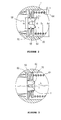
- a longitudinal sectional view of a thrust bearing assembly in accordance with the invention as applied to a variable displacement swash plate type compressor, for improving the relation between an inner and an outer diameter of a driving and a stationary races and a center bore and an outer diameter of a driving shaft.
- a driving race 80 and a stationary race 82 are closely fixed at both sides of a thrust bearing 58, respectively.
- the driving race 80 at the left side rotates together with the driving shaft 20, and the stationary race 82 at the right side is close to one end of a resilient member 64 to support both of the driving shaft 20 and the thrust bearing 62.
- the invention changes the relations between the inner and the outer diameters of the driving race 80 and the outer diameter of the driving shaft 20 and a diameter (d4) of the center bore 4 in which the driving shaft 20 is inserted.
- the driving race 80 is designed to have the inner diameter (d1) almost equal to the outer diameter (d2) of the driving shaft 20 so as to be fixedly engaged with the driving shaft 20.
- the stationary race 82 is designed to have the inner diameter (d3) greater than the outer diameter (d2) of the driving shaft 20 to prevent the stationary race 82 from coming into contact with the outer periphery of driving shaft 20. That is, the inner diameter (d1) of the driving race 80 is smaller than the inner diameter (d3) of the stationary race 82 (d1 ⁇ d3).
- the stationary race 82 does not come into contact with the driving shaft 20
- the driving shaft 20 can rotate smoothly
- the driving race 80 does not come into contact with the surface 4a of the center bore 4, it can rotate smoothly. Further, since there is no frictional load, the service life of the compressor is extended and the noise of the compressor is reduced.
- the driving race 80, the thrust bearing 58 and the stationary race 82 are assembled to the driving shaft 20 in order.
- the driving race 80 and the stationary race 82 are similar to each other in shape, there is a likelihood that the driving race 80 and the stationary race 82 be mis-assembled in the wrong, i.e. reverse, order. Accordingly, it is advantageous that their sizes are different from each other so as to be visually distinguished.
- the driving race 80 and the stationary race 82 may be fabricated in such a way that the outer diameter (D1) of the driving race 80 and the outer diameter (D3) of the stationary race 82 are different to each other.
- the outer diameter (D1) of the driving race is smaller than the outer diameter (D3) of the stationary race 82 (D1 ⁇ D3).
- the races 80 and 82 are assembled to the driving shaft 20, they are visually distinguishable, thereby preventing the mis-assembly thereof.
- the stationary race 82 which has the outer diameter smaller than that of the driving race 80 is preferentially assembled to the driving shaft 20.
- the present invention is described based on the preferred embodiment shown in the drawings, the preferred embodiment is just exemplary and the present invention may be applied not only to a swash plate compressor but also to other devices in which a thrust bearing structure is provided, for instance a compressor having variable capacity or a scroll type compressor.
Landscapes
- Engineering & Computer Science (AREA)
- General Engineering & Computer Science (AREA)
- Mechanical Engineering (AREA)
- Compressors, Vaccum Pumps And Other Relevant Systems (AREA)
- Compressor (AREA)
Applications Claiming Priority (2)
| Application Number | Priority Date | Filing Date | Title |
|---|---|---|---|
| KR1020010038757A KR100748140B1 (ko) | 2001-06-30 | 2001-06-30 | 가변용량 사판식 압축기의 구동축 지지용 스러스트 베어링지지구조 |
| KR2001038757 | 2001-06-30 |
Publications (3)
| Publication Number | Publication Date |
|---|---|
| EP1270942A2 true EP1270942A2 (fr) | 2003-01-02 |
| EP1270942A3 EP1270942A3 (fr) | 2004-06-30 |
| EP1270942B1 EP1270942B1 (fr) | 2006-03-08 |
Family
ID=36202163
Family Applications (1)
| Application Number | Title | Priority Date | Filing Date |
|---|---|---|---|
| EP01308171A Expired - Lifetime EP1270942B1 (fr) | 2001-06-30 | 2001-09-26 | Palier de poussée pour le plateau en biais d'un compresseur |
Country Status (6)
| Country | Link |
|---|---|
| US (1) | US6568312B2 (fr) |
| EP (1) | EP1270942B1 (fr) |
| JP (1) | JP3728533B2 (fr) |
| KR (1) | KR100748140B1 (fr) |
| DE (1) | DE60117729T2 (fr) |
| PT (1) | PT1270942E (fr) |
Cited By (1)
| Publication number | Priority date | Publication date | Assignee | Title |
|---|---|---|---|---|
| FR2886686A1 (fr) * | 2005-06-06 | 2006-12-08 | Peugeot Citroen Automobiles Sa | Systeme de lancement d'un moteur thermique d'un vehicule automobile |
Families Citing this family (2)
| Publication number | Priority date | Publication date | Assignee | Title |
|---|---|---|---|---|
| KR102717000B1 (ko) * | 2019-01-08 | 2024-10-15 | 한온시스템 주식회사 | 압축기 |
| WO2023121160A1 (fr) * | 2021-12-24 | 2023-06-29 | 한온시스템 주식회사 | Compresseur électrique |
Family Cites Families (9)
| Publication number | Priority date | Publication date | Assignee | Title |
|---|---|---|---|---|
| US3281192A (en) * | 1964-03-16 | 1966-10-25 | Zimmermann & Jansen Gmbh | Thrust-bearing |
| US4907899A (en) * | 1989-02-28 | 1990-03-13 | The Torrington Company | Thrust bearing assembly feature |
| JP2946696B2 (ja) * | 1990-09-03 | 1999-09-06 | 株式会社豊田自動織機製作所 | 斜板式圧縮機 |
| US5813222A (en) * | 1994-10-07 | 1998-09-29 | Appleby; Anthony John | Method and apparatus for heating a catalytic converter to reduce emissions |
| US5630670A (en) * | 1995-06-03 | 1997-05-20 | INA W alzlager Schaeffler KG | Axial rolling bearing |
| JPH0972278A (ja) * | 1995-09-07 | 1997-03-18 | Denso Corp | 斜板式圧縮機 |
| KR19980060329U (ko) * | 1997-03-10 | 1998-11-05 | 김욱한 | 사판식 압축기 |
| KR200156018Y1 (ko) * | 1997-09-12 | 1999-09-01 | 신영주 | 사판식 압축기 |
| JP2000303951A (ja) * | 1999-04-20 | 2000-10-31 | Toyota Autom Loom Works Ltd | ピストン式圧縮機 |
-
2001
- 2001-06-30 KR KR1020010038757A patent/KR100748140B1/ko not_active Expired - Lifetime
- 2001-09-26 DE DE60117729T patent/DE60117729T2/de not_active Expired - Lifetime
- 2001-09-26 EP EP01308171A patent/EP1270942B1/fr not_active Expired - Lifetime
- 2001-09-26 PT PT01308171T patent/PT1270942E/pt unknown
- 2001-09-28 US US09/964,799 patent/US6568312B2/en not_active Expired - Lifetime
- 2001-09-28 JP JP2001303539A patent/JP3728533B2/ja not_active Expired - Lifetime
Cited By (1)
| Publication number | Priority date | Publication date | Assignee | Title |
|---|---|---|---|---|
| FR2886686A1 (fr) * | 2005-06-06 | 2006-12-08 | Peugeot Citroen Automobiles Sa | Systeme de lancement d'un moteur thermique d'un vehicule automobile |
Also Published As
| Publication number | Publication date |
|---|---|
| DE60117729T2 (de) | 2006-11-23 |
| KR20030002024A (ko) | 2003-01-08 |
| KR100748140B1 (ko) | 2007-08-09 |
| PT1270942E (pt) | 2006-07-31 |
| DE60117729D1 (de) | 2006-05-04 |
| JP3728533B2 (ja) | 2005-12-21 |
| US6568312B2 (en) | 2003-05-27 |
| US20030000378A1 (en) | 2003-01-02 |
| EP1270942B1 (fr) | 2006-03-08 |
| EP1270942A3 (fr) | 2004-06-30 |
| JP2003028058A (ja) | 2003-01-29 |
Similar Documents
| Publication | Publication Date | Title |
|---|---|---|
| US5615599A (en) | Guiding mechanism for reciprocating piston of piston-type compressor | |
| US6186048B1 (en) | Variable displacement compressor | |
| US20010007635A1 (en) | Electric type swash plate compressor | |
| CN210423002U (zh) | 具有衬套的压缩机 | |
| US6024009A (en) | Reciprocating pistons of piston-type compressor | |
| EP0809024A1 (fr) | Piston alternatif de compresseur à piston | |
| US6203284B1 (en) | Valve arrangement at the discharge chamber of a variable displacement compressor | |
| KR100193911B1 (ko) | 사판식 압축기 | |
| US6126406A (en) | Variable displacement compressor | |
| EP1270942B1 (fr) | Palier de poussée pour le plateau en biais d'un compresseur | |
| KR100282043B1 (ko) | 가변용량 사판식 압축기 | |
| US6212995B1 (en) | Variable-displacement inclined plate compressor | |
| EP1098090A2 (fr) | Compresseur à plateau en biais à piston à simple tête avec piston creux et nervuré | |
| JP4314405B2 (ja) | 可変容量型斜板式圧縮機 | |
| EP0911521B1 (fr) | Gorges de lubrification dans le support rotatif d'un compresseur à plateau-came | |
| JP2000110717A (ja) | 斜板型可変容量圧縮機 | |
| KR100875905B1 (ko) | 가변용량형 사판식 압축기 | |
| KR100903060B1 (ko) | 사판식 압축기의 샤프트 지지구조 | |
| JP4344972B2 (ja) | 斜板式圧縮機 | |
| JP3259487B2 (ja) | 容量可変型斜板式圧縮機 | |
| US20010043866A1 (en) | Electric compressor | |
| US6386090B2 (en) | Piston type compressor | |
| EP1211416A1 (fr) | Compresseur du type a plateau oscillant | |
| JPH0121355B2 (fr) | ||
| JP4329053B2 (ja) | 可変容量型斜板式圧縮機 |
Legal Events
| Date | Code | Title | Description |
|---|---|---|---|
| PUAI | Public reference made under article 153(3) epc to a published international application that has entered the european phase |
Free format text: ORIGINAL CODE: 0009012 |
|
| AK | Designated contracting states |
Kind code of ref document: A2 Designated state(s): AT BE CH CY DE DK ES FI FR GB GR IE IT LI LU MC NL PT SE TR |
|
| AX | Request for extension of the european patent |
Free format text: AL;LT;LV;MK;RO;SI |
|
| PUAL | Search report despatched |
Free format text: ORIGINAL CODE: 0009013 |
|
| AK | Designated contracting states |
Kind code of ref document: A3 Designated state(s): AT BE CH CY DE DK ES FI FR GB GR IE IT LI LU MC NL PT SE TR |
|
| AX | Request for extension of the european patent |
Extension state: AL LT LV MK RO SI |
|
| 17P | Request for examination filed |
Effective date: 20040903 |
|
| 17Q | First examination report despatched |
Effective date: 20050112 |
|
| AKX | Designation fees paid |
Designated state(s): DE FR GB IT PT SE |
|
| GRAP | Despatch of communication of intention to grant a patent |
Free format text: ORIGINAL CODE: EPIDOSNIGR1 |
|
| GRAS | Grant fee paid |
Free format text: ORIGINAL CODE: EPIDOSNIGR3 |
|
| GRAA | (expected) grant |
Free format text: ORIGINAL CODE: 0009210 |
|
| AK | Designated contracting states |
Kind code of ref document: B1 Designated state(s): DE FR GB IT PT SE |
|
| REG | Reference to a national code |
Ref country code: GB Ref legal event code: FG4D |
|
| REF | Corresponds to: |
Ref document number: 60117729 Country of ref document: DE Date of ref document: 20060504 Kind code of ref document: P |
|
| REG | Reference to a national code |
Ref country code: SE Ref legal event code: TRGR |
|
| REG | Reference to a national code |
Ref country code: PT Ref legal event code: SC4A Effective date: 20060602 |
|
| ET | Fr: translation filed | ||
| PLBE | No opposition filed within time limit |
Free format text: ORIGINAL CODE: 0009261 |
|
| STAA | Information on the status of an ep patent application or granted ep patent |
Free format text: STATUS: NO OPPOSITION FILED WITHIN TIME LIMIT |
|
| 26N | No opposition filed |
Effective date: 20061211 |
|
| REG | Reference to a national code |
Ref country code: DE Ref legal event code: R082 Ref document number: 60117729 Country of ref document: DE Representative=s name: KOHLER SCHMID MOEBUS PATENTANWAELTE, DE |
|
| REG | Reference to a national code |
Ref country code: FR Ref legal event code: CD Owner name: HALLA VISTEON CLIMATE CONTROL CORPORATION Effective date: 20130827 |
|
| REG | Reference to a national code |
Ref country code: DE Ref legal event code: R082 Ref document number: 60117729 Country of ref document: DE Representative=s name: KOHLER SCHMID MOEBUS PATENTANWAELTE PARTNERSCH, DE Effective date: 20130910 Ref country code: DE Ref legal event code: R082 Ref document number: 60117729 Country of ref document: DE Representative=s name: KOHLER SCHMID MOEBUS PATENTANWAELTE, DE Effective date: 20130910 Ref country code: DE Ref legal event code: R081 Ref document number: 60117729 Country of ref document: DE Owner name: HANON SYSTEMS, KR Free format text: FORMER OWNER: HALLA CLIMATE CONTROL CORP., DAEJEON, KR Effective date: 20130910 Ref country code: DE Ref legal event code: R081 Ref document number: 60117729 Country of ref document: DE Owner name: HALLA VISTEON CLIMATE CONTROL CORP., KR Free format text: FORMER OWNER: HALLA CLIMATE CONTROL CORP., DAEJEON, KR Effective date: 20130910 |
|
| REG | Reference to a national code |
Ref country code: FR Ref legal event code: PLFP Year of fee payment: 16 |
|
| REG | Reference to a national code |
Ref country code: DE Ref legal event code: R082 Ref document number: 60117729 Country of ref document: DE Representative=s name: KOHLER SCHMID MOEBUS PATENTANWAELTE PARTNERSCH, DE Ref country code: DE Ref legal event code: R081 Ref document number: 60117729 Country of ref document: DE Owner name: HANON SYSTEMS, KR Free format text: FORMER OWNER: HALLA VISTEON CLIMATE CONTROL CORP., DAEJEON, KR |
|
| REG | Reference to a national code |
Ref country code: FR Ref legal event code: CD Owner name: HANON SYSTEMS Effective date: 20161212 |
|
| REG | Reference to a national code |
Ref country code: FR Ref legal event code: PLFP Year of fee payment: 17 |
|
| REG | Reference to a national code |
Ref country code: FR Ref legal event code: PLFP Year of fee payment: 18 |
|
| PGFP | Annual fee paid to national office [announced via postgrant information from national office to epo] |
Ref country code: GB Payment date: 20200916 Year of fee payment: 20 Ref country code: FR Payment date: 20200812 Year of fee payment: 20 Ref country code: DE Payment date: 20200916 Year of fee payment: 20 |
|
| PGFP | Annual fee paid to national office [announced via postgrant information from national office to epo] |
Ref country code: IT Payment date: 20200812 Year of fee payment: 20 Ref country code: SE Payment date: 20200910 Year of fee payment: 20 |
|
| PGFP | Annual fee paid to national office [announced via postgrant information from national office to epo] |
Ref country code: PT Payment date: 20201005 Year of fee payment: 20 |
|
| REG | Reference to a national code |
Ref country code: DE Ref legal event code: R071 Ref document number: 60117729 Country of ref document: DE |
|
| REG | Reference to a national code |
Ref country code: GB Ref legal event code: PE20 Expiry date: 20210925 |
|
| PG25 | Lapsed in a contracting state [announced via postgrant information from national office to epo] |
Ref country code: GB Free format text: LAPSE BECAUSE OF EXPIRATION OF PROTECTION Effective date: 20210925 |
|
| PG25 | Lapsed in a contracting state [announced via postgrant information from national office to epo] |
Ref country code: PT Free format text: LAPSE BECAUSE OF EXPIRATION OF PROTECTION Effective date: 20211006 |