EP1270969B2 - Kugelgelenk - Google Patents
Kugelgelenk Download PDFInfo
- Publication number
- EP1270969B2 EP1270969B2 EP01118935.4A EP01118935A EP1270969B2 EP 1270969 B2 EP1270969 B2 EP 1270969B2 EP 01118935 A EP01118935 A EP 01118935A EP 1270969 B2 EP1270969 B2 EP 1270969B2
- Authority
- EP
- European Patent Office
- Prior art keywords
- ball
- bearing ring
- bearing
- ring
- housing
- Prior art date
- Legal status (The legal status is an assumption and is not a legal conclusion. Google has not performed a legal analysis and makes no representation as to the accuracy of the status listed.)
- Expired - Lifetime
Links
- 239000000463 material Substances 0.000 claims description 12
- 229910052751 metal Inorganic materials 0.000 claims description 5
- 239000002184 metal Substances 0.000 claims description 5
- 239000000919 ceramic Substances 0.000 claims description 4
- 238000007789 sealing Methods 0.000 claims description 4
- 239000010959 steel Substances 0.000 description 3
- 229910000760 Hardened steel Inorganic materials 0.000 description 2
- 229910000831 Steel Inorganic materials 0.000 description 2
- 229910045601 alloy Inorganic materials 0.000 description 2
- 239000000956 alloy Substances 0.000 description 2
- POIUWJQBRNEFGX-XAMSXPGMSA-N cathelicidin Chemical compound C([C@@H](C(=O)N[C@@H](CCCNC(N)=N)C(=O)N[C@@H](CCCCN)C(=O)N[C@@H](CO)C(=O)N[C@@H](CCCCN)C(=O)N[C@@H](CCC(O)=O)C(=O)N[C@@H](CCCCN)C(=O)N[C@@H]([C@@H](C)CC)C(=O)NCC(=O)N[C@@H](CCCCN)C(=O)N[C@@H](CCC(O)=O)C(=O)N[C@@H](CC=1C=CC=CC=1)C(=O)N[C@@H](CCCCN)C(=O)N[C@@H](CCCNC(N)=N)C(=O)N[C@@H]([C@@H](C)CC)C(=O)N[C@@H](C(C)C)C(=O)N[C@@H](CCC(N)=O)C(=O)N[C@@H](CCCNC(N)=N)C(=O)N[C@@H]([C@@H](C)CC)C(=O)N[C@@H](CCCCN)C(=O)N[C@@H](CC(O)=O)C(=O)N[C@@H](CC=1C=CC=CC=1)C(=O)N[C@@H](CC(C)C)C(=O)N[C@@H](CCCNC(N)=N)C(=O)N[C@@H](CC(N)=O)C(=O)N[C@@H](CC(C)C)C(=O)N[C@@H](C(C)C)C(=O)N1[C@@H](CCC1)C(=O)N[C@@H](CCCNC(N)=N)C(=O)N[C@@H]([C@@H](C)O)C(=O)N[C@@H](CCC(O)=O)C(=O)N[C@@H](CO)C(O)=O)NC(=O)[C@H](CC=1C=CC=CC=1)NC(=O)[C@H](CC(O)=O)NC(=O)CNC(=O)[C@H](CC(C)C)NC(=O)[C@@H](N)CC(C)C)C1=CC=CC=C1 POIUWJQBRNEFGX-XAMSXPGMSA-N 0.000 description 2
- 238000010276 construction Methods 0.000 description 2
- 238000005516 engineering process Methods 0.000 description 2
- 239000004519 grease Substances 0.000 description 2
- 238000009434 installation Methods 0.000 description 2
- 239000004033 plastic Substances 0.000 description 2
- 229910000838 Al alloy Inorganic materials 0.000 description 1
- 229910000851 Alloy steel Inorganic materials 0.000 description 1
- 208000031872 Body Remains Diseases 0.000 description 1
- 229910000906 Bronze Inorganic materials 0.000 description 1
- 229910001018 Cast iron Inorganic materials 0.000 description 1
- CWYNVVGOOAEACU-UHFFFAOYSA-N Fe2+ Chemical compound [Fe+2] CWYNVVGOOAEACU-UHFFFAOYSA-N 0.000 description 1
- 238000010521 absorption reaction Methods 0.000 description 1
- 239000010974 bronze Substances 0.000 description 1
- 238000000576 coating method Methods 0.000 description 1
- 239000002131 composite material Substances 0.000 description 1
- KUNSUQLRTQLHQQ-UHFFFAOYSA-N copper tin Chemical compound [Cu].[Sn] KUNSUQLRTQLHQQ-UHFFFAOYSA-N 0.000 description 1
- 230000001419 dependent effect Effects 0.000 description 1
- 238000010438 heat treatment Methods 0.000 description 1
- 238000005461 lubrication Methods 0.000 description 1
- 238000011089 mechanical engineering Methods 0.000 description 1
- 239000007921 spray Substances 0.000 description 1
- 238000011282 treatment Methods 0.000 description 1
- XLYOFNOQVPJJNP-UHFFFAOYSA-N water Substances O XLYOFNOQVPJJNP-UHFFFAOYSA-N 0.000 description 1
Images


Classifications
-
- F—MECHANICAL ENGINEERING; LIGHTING; HEATING; WEAPONS; BLASTING
- F16—ENGINEERING ELEMENTS AND UNITS; GENERAL MEASURES FOR PRODUCING AND MAINTAINING EFFECTIVE FUNCTIONING OF MACHINES OR INSTALLATIONS; THERMAL INSULATION IN GENERAL
- F16C—SHAFTS; FLEXIBLE SHAFTS; ELEMENTS OR CRANKSHAFT MECHANISMS; ROTARY BODIES OTHER THAN GEARING ELEMENTS; BEARINGS
- F16C23/00—Bearings for exclusively rotary movement adjustable for aligning or positioning
- F16C23/02—Sliding-contact bearings
- F16C23/04—Sliding-contact bearings self-adjusting
- F16C23/043—Sliding-contact bearings self-adjusting with spherical surfaces, e.g. spherical plain bearings
- F16C23/045—Sliding-contact bearings self-adjusting with spherical surfaces, e.g. spherical plain bearings for radial load mainly, e.g. radial spherical plain bearings
-
- F—MECHANICAL ENGINEERING; LIGHTING; HEATING; WEAPONS; BLASTING
- F16—ENGINEERING ELEMENTS AND UNITS; GENERAL MEASURES FOR PRODUCING AND MAINTAINING EFFECTIVE FUNCTIONING OF MACHINES OR INSTALLATIONS; THERMAL INSULATION IN GENERAL
- F16C—SHAFTS; FLEXIBLE SHAFTS; ELEMENTS OR CRANKSHAFT MECHANISMS; ROTARY BODIES OTHER THAN GEARING ELEMENTS; BEARINGS
- F16C11/00—Pivots; Pivotal connections
- F16C11/04—Pivotal connections
- F16C11/06—Ball-joints; Other joints having more than one degree of angular freedom, i.e. universal joints
- F16C11/0619—Ball-joints; Other joints having more than one degree of angular freedom, i.e. universal joints the female part comprising a blind socket receiving the male part
- F16C11/0623—Construction or details of the socket member
- F16C11/0628—Construction or details of the socket member with linings
-
- F—MECHANICAL ENGINEERING; LIGHTING; HEATING; WEAPONS; BLASTING
- F16—ENGINEERING ELEMENTS AND UNITS; GENERAL MEASURES FOR PRODUCING AND MAINTAINING EFFECTIVE FUNCTIONING OF MACHINES OR INSTALLATIONS; THERMAL INSULATION IN GENERAL
- F16C—SHAFTS; FLEXIBLE SHAFTS; ELEMENTS OR CRANKSHAFT MECHANISMS; ROTARY BODIES OTHER THAN GEARING ELEMENTS; BEARINGS
- F16C11/00—Pivots; Pivotal connections
- F16C11/04—Pivotal connections
- F16C11/06—Ball-joints; Other joints having more than one degree of angular freedom, i.e. universal joints
- F16C11/0666—Sealing means between the socket and the inner member shaft
- F16C11/0671—Sealing means between the socket and the inner member shaft allowing operative relative movement of joint parts due to flexing of the sealing means
Definitions
- the invention relates to a ball joint
- US Pat. No. 6,030,141 A describes a ball and socket joint with a ball-shaped bearing surface of a joint housing, which is formed on a bearing shell arranged as a separate part in the joint housing.
- the bearing shell has a radially outwardly projecting edge and ends in front of the passage opening in the lower part of the joint housing.
- the usable as a separate part in the joint housing bearing shells can be made of any suitable material, eg. Hardened steel, plastic or ceramic.
- Ball joints are used in many areas of technology, such as in mechanical engineering, automotive engineering or in agricultural technology and construction machinery.
- a ball joint consists of a housing, a bearing shell disposed therein and a ball or a ball pin, which are guided in the bearing shell.
- a hardened bearing shell made of sheet steel is provided.
- the ball piece is stored. So that the ball piece retains its desired position in the bearing shell, it is pressed by an upper bearing shell by spring force into the spherical part of the bearing shell.
- a disadvantage of this arrangement is that the contact surface between the ball and bearing shell is given only by the surface of a spherical layer, which does not include the ball over the largest diameter, namely the equator. As a result, the surface pressure at the contact surface is high for a given radial force. In addition, with an axial force occurring in the direction of the cylindrically shaped side of the bearing shell, there is the possibility that a ball stud lifts against the spring force from the bearing shell. This leads to increased wear and noise in the joint.
- the present invention is defined by claim 1. An embodiment results from the dependent claim 2.
- the ball joint according to the invention has a bearing ring in which a spherical body is guided. Furthermore, a housing is provided which surrounds the bearing ring.
- the bearing ring is formed so that it completely surrounds the spherical body in the region of an equator and has a first inner edge and a second inner edge, each defining a surface and the two surfaces are dimensioned differently.
- the surfaces defined by the inner edges represent the ball exit surfaces.
- the bearing ring is designed so that the ball exit surfaces are different on both sides, ie the spherical body is further enclosed on one side of the one shoulder of the bearing ring on the other side.
- the bearing ring according to the invention thus has an asymmetrical structure or cross section.
- Material for the bearing ring is a metal, a ceramic or an alloy form or material combination of the materials mentioned.
- the bearing ring consists of an upper and lower ring portion, wherein the surface of the lower ring portion, which is in contact with the spherical body below the equator, is larger than the corresponding area at the upper ring portion above the equator.
- On the housing a closure lid is placed on the bearing ring is a sleeve attached.
- a circumferential sealing bellows and a support ring are provided.
- the degree of wear on the contact surface ball bearing storage to falling out of the spherical body from the bearing ring is significantly higher compared to a symmetrical ring.
- the deflection angle of the spherical body remains, since this is limited by the housing shape and not by the bearing ring.
- the asymmetrically designed bearing ring can of course also be used for applications outside the steering range, in which increased axial stresses can occur in one direction.
- the ball joint has less play, which reduces wear.
- a larger contact area results in a reduced surface pressure and a lower wear and a larger load absorption for a given joint size. For the same load data therefore smaller and thus cheaper joints can be used.
- the material for the bearing ring is metal, e.g. Ferrous metal (e.g., steel, cast iron material), nonferrous metal (e.g., bronze), or ceramics.
- Ferrous metal e.g., steel, cast iron material
- nonferrous metal e.g., bronze
- ceramics e.g., ceramics
- all alloy forms and material combinations of the materials mentioned are conceivable.
- the invention encompasses all material treatments (e.g., heat treatments) and surface coatings, as well as all surface patterns (e.g., grease groove systems).
- the bearing ring according to the invention can be designed as a one-piece component that is blown up or separated at one point.
- the spherical body is mounted on the side of the larger diameter bearing ring by expanding it. A mutual positioning of several individual bearing parts is eliminated.
- the bearing ring can also be constructed of several parts or segments.
- the ball joint according to the invention is particularly suitable for use in tie rods and handlebars for vehicles of all kinds.
- the spherical body is part of a ball stud.
- the ball stud has a spherical body with a molded pin, which protrudes from the joint bearing.
- the bearing ring is fixed by means of a sleeve and an attached closure cap and the housing is closed.
- the exit side of the ball stud is biased a support ring pushed onto the counter cone or Kugelzapfenhals. Then the sealing bellows is mounted.
- the joint is preferably filled with special grease and thereby lubricated.
- special grease In an embodiment of the invention may be provided on the inside or the ball raceway of the bearing ring lubrication.
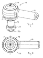
- FIG. 1 shows a ball joint according to the invention, denoted overall by the reference numeral 10, in a schematic representation.
- a ball pin 12 which is guided in a not visible in this illustration bearing ring.
- This bearing ring is surrounded by a housing 14.
- a connecting piece 16 Placed on the housing 14 is a closure lid 18, which closes the housing 14 in the upper region.
- the ball pin 12 protrudes from this.
- a thread 20 is formed at the lower end of the ball stud 12.
- a nut 22 is turned on.
- FIG. 2 the ball joint 10 according to the invention is shown in plan view.
- the closure cap 18 is placed on the housing 14 of the ball joint 10 and prevents foreign bodies and spray water in the housing 14 of the ball joint 10 arrive.
- Formed on the housing 14 is the elongated connector 16.
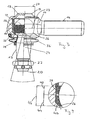
- FIG. 3 the ball joint 10 according to the invention is shown in a sectional view.
- the illustration shows that the ball pin 12 consists of a pin member 24 and a ball member 26.
- Arrow 27 indicates the diameter of the ball portion 26 in the region of its largest circumference.
- the ball part 26 is guided in a bearing ring 28.
- the ball part in the region of the largest circumference, namely in the region of the equator 29, completely enclosed by the bearing ring 28.
- the ball member 26 is snapped into the bearing ring 28 and forms together with this a spherical plain bearing, which is accommodated in the housing 14.
- a sleeve 30 is also provided in the housing and serves to fix the bearing ring 28 in the housing 14.
- the spherical plain bearing can be used in all possible constructions.
- the closure cap 18 is seated on the sleeve 30, which in turn is arranged on the bearing ring 28. Furthermore, a circumferential sealing bellows 32 and a support ring 34 is provided.
- the designated by the reference numeral 36 section is in FIG. 4 shown in an enlarged view.
- FIG. 4 shows the bearing ring 28, which consists of an upper ring portion 38 and a lower ring portion 40. It can be seen that the lower ring portion 40 is pulled far down. The lower ring portion 40 thus has a greater vertical extent than the upper ring portion 38, as indicated by arrows 42 and 44. The total vertical extent of the bearing ring 28 is illustrated by arrow 46.
- the bearing ring 28 is shown in a perspective view. Also in this illustration, the upper ring portion 38 and the lower ring portion 40 can be seen. Between the upper ring portion 38 and the lower ring portion 40, a groove 48 is formed in the bearing ring 28. Furthermore, located in the bearing ring 28 in the region of the groove 48 two opposing openings 50 for a possibly necessary Nachschmier réellekeit.
- the bearing ring 28 shown can thus be used in a greasable but also in a maintenance-free spherical plain bearings.
- this In the upper region of the bearing ring 28, this has a first inner edge 52, which defines a surface with a circular circumference in this case. This circumference determines the inner diameter of the bearing ring 28 in its upper region.
- a second inner edge 54 is provided, which also forms a circular circumference. The diameter of this circumference is equal to the inner diameter of the bearing ring 28 in its lower region.
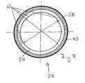
- the bearing ring 28 is shown in cross section. It can be clearly seen that the lower ring portion 40 projects further into the interior of the bearing ring 28 than the upper ring portion 38.
- the first inner edge 52 of the bearing ring 28, namely the upper inner edge of the upper ring portion 38 forms a circular circumference.
- the diameter of this circumference is given by arrow 56.
- the lower inner edge of the lower ring portion forms 40, namely the second inner edge 54, also a circular circumference.
- the diameter of this circumference is illustrated by arrow 58 and significantly smaller than the diameter of the aforementioned circumference.
- the surfaces defined by the inner edges 52 and 54 are thus dimensioned differently. These do not have to be circular. Likewise, the surfaces do not have to be flat.
- FIG. 7 A section through the bearing ring 28 along the line VII - VII in FIG. 6 is in FIG. 7 shown.
- the surface indicated by reference numeral 62 namely, the inner surface of the lower ring portion 40, constitutes part of the ball raceway surface.
- the ball raceway surface is the surface which contacts the surface of the ball.
- this ball raceway is compared to that of conventional bearing rings significantly increased.
- the diameter of the inner edge 54, indicated by the arrow 58, which forms a circular circumference in the embodiment shown here, can also be clearly seen.
- FIG. 8 a joint bearing is shown, which is designated by the reference numeral 64.
- the ball part 26 of the ball stud 12 is guided in the bearing ring 28.
- the pin member 24 of the ball pin 12 projects out of the bearing ring 28.
- the pivot bearing 64 is in FIG. 9 shown in a sectional view. It can be seen how the ball part 26 is guided in the bearing ring 28. In this case, the ball part in the region of the equator 66, ie in the region of the largest circumference of the ball part 26, completely enclosed by the bearing ring 28.
Landscapes
- Engineering & Computer Science (AREA)
- General Engineering & Computer Science (AREA)
- Mechanical Engineering (AREA)
- Pivots And Pivotal Connections (AREA)
- Pens And Brushes (AREA)
- Support Of The Bearing (AREA)
Description
- Die Erfindung betrifft ein Kugelgelenk
- Die Druckschrift US 6 030 141 A beschreibt ein Kugelgelenk mit einer kugelringförmigen Lagerfläche eines Gelenkgehäuses, welche an einer als separates Teil im Gelenkgehäuse angeordneten Lagerschale ausgebildet ist. Die Lagerschale weist einen radial nach außen abstehenden Rand auf und endet vor der Durchtrittsöffnung im unteren Teil des Gelenkgehäuses. Die als separates Teil in das Gelenkgehäuse einsetzbaren Lagerschalen können aus jedem geeigneten Material, bspw. gehärtetem Stahl, Kunststoff oder Keramik bestehen.
- Kugelgelenke werden in vielen Bereichen der Technik, wie bspw. im Maschinenbau, Kraftfahrzeugwesen oder auch in der Agrartechnik sowie bei Baumaschinen, eingesetzt. Üblicherweise besteht ein Kugelgelenk aus einem Gehäuse, einer darin angeordneten Lagerschale und einem Kugelstück oder einem Kugelzapfen, die in der Lagerschale geführt sind. Es gibt viele verschiedene konstruktive Ausführungen, die ebenso wie die verwendeten Materialien in Abhängigkeit von der Anwendung gewählt werden. Bekannt ist bspw. in einem Gehäuse aus einer Stahl- oder Aluminiumlegierung eine Lagerschale oder mehrere Lagerschalenteile aus einem geeigneten Kunststoff, einem gehärteten Stahlblech oder einem Verbundmaterial vorzusehen.
- Bei einem weit verbreiteten Konstruktionsprinzip in der Kraftfahrzeugtechnik ist eine gehärtete Lagerschale aus Stahlblech vorgesehen. In dieser ist das Kugelstück gelagert. Damit das Kugelstück seine gewünschte Lage in der Lagerschale behält, wird es mit einer oberen Lagerschale durch Federkraft in den kugelförmigen Teil der Lagerschale gepreßt.
- Nachteilig bei dieser Anordnung ist, daß die Kontaktfläche zwischen Kugel und Lagerschale nur durch die Oberfläche einer Kugelschicht gegeben ist, die die Kugel nicht über den größten Durchmesser, nämlich den Äquator, hinaus umfaßt. Dadurch ist bei gegebener Radialkraft die Flächenpressung an der Kontaktfläche hoch. Darüber hinaus besteht bei einer auftretenden axialen Kraft in Richtung der zylindrisch gestalteten Seite der Lagerschale die Möglichkeit, daß sich ein Kugelzapfen gegen die Federkraft von der Lagerschale abhebt. Dies führt zu einem erhöhten Verschleiß und zu Geräuschen im Gelenk.
- Zur Vermeidung der vorstehend genannten Nachteile ist es bekannt, anstelle der Lagerschale einen sogenannten Lagerring zu verwenden, der der Ausführung eines Gelenklagerauβenrings entspricht. Bei einem Kugelgelenk mit Lagerring wird das Kugelstück von dem Lagerring umfaßt. Ist die Kugel des Kugelzapfens oder des Kugelstücks und die Kugellauffläche des Lagerrings genau gefertigt, ergibt sich eine große Kontaktfläche und somit eine geringe Flächenpressung bei gegebener Radialkraft. Auf diese Weise wird der Verschleiß verringert und die mögliche Kraftaufnahme bei gegebener Gelenkgröße erhöht. Durch die Umschließung der Kugel durch den Lagerring ist eine exakte Führung des Kugelstücks gesichert. Das Spiel in axialer und in radialer Richtung ist verringert. Ein Abheben der Kugel aus dem Lagerring ist nicht möglich. Desweiteren können Axialkräfte aufgenommen werden.
- Die vorliegende Erfindung ist durch den Anspruch 1 definiert. Eine Ausführungsform ergibt sich durch den abhängigen Anspruch 2.
- Das erfindungsgemäße Kugelgelenk weist einen Lagerring auf, in dem ein kugelförmiger Körper geführt ist. Weiterhin ist ein Gehäuse vorgesehen, das den Lagerring umgibt. Der Lagerring ist so ausgebildet, daß dieser den kugelförmigen Körper im Bereich eines Äquators vollständig umschließt und einen ersten inneren Rand und einen zweiten inneren Rand aufweist, die jeweils eine Fläche definieren und die beiden Flächen unterschiedlich dimensioniert sind. Die durch die inneren Ränder definierten Flächen stellen die Kugelaustrittsflächen dar. Der Lagerring ist dabei so ausgebildet, daß die Kugelaustrittsflächen auf beiden Seiten verschieden sind, d.h. der kugelförmige Körper auf einer Seite von der einen Schulter des Lagerrings weiter umschlossen ist als auf der anderen Seite. Der erfindungsgemäße Lagerring weist somit einen asymmetrischen Aufbau bzw. Querschnitt auf. Werkstoff für den Lagerring ist ein Metall, eine Keramik oder eine Legierungsform oder Werkstoffkombination der genannten Werkstoffe. Der Lagerring besteht aus einem oberen und unteren Ringabschnitt, wobei die Fläche des unteren Ringabschnitts, die in Berührung mit dem kugelförmigen Körper unterhalb des Äquators steht, größer als die entsprechende Fläche bei dem oberen Ringabschnitt oberhalb des Äquators ist. Auf das Gehäuse ist ein Verschlußdeckel aufgesetzt, auf den Lagerring ist eine Hülse aufgesetzt. Ein umlaufender Dichtungsbalg und ein Stützring sind vorgesehen.
- Durch die Asymmetrie des Lagerrings ergeben sich viele Vorteile. Im Vergleich zu bekannten Lagerringen kann jetzt bei gleicher Gelenkgröße bedingt durch eine größere Kugellauffläche ein größerer Radialdruck aufgenommen werden. Eine größere Kontaktfläche zwischen Kugel und Lagerring reduziert bei gleicher Belastung die Flächenpressung, d.h. der Verschleiß wird geringer und die Lebensdauer wesentlich erhöht. Die größere Umschließung des asymmetrischen Lagerrings minimiert das Axialspiel im Neuzustand als auch in der Verschleißphase. Die mögliche Geräuschentwicklung, bspw. beim Einsatz in einem Kraftfahrzeug bei ungünstiger Fahrbahnbeschaffenheit wird weiter reduziert.
- In Richtung der größeren Umschließung der Kugel durch den Lagerring kann auch eine erhöhte Axialkraft aufgenommen werden. Dies ist dort notwendig, wo durch die Einbaulage des Gelenks oder der Lenkstange infolge des Eigengewichts und Schwingungen besonders hohe Axialkräfte auftreten können.
- Die erhöhte Belastungsmöglichkeit erlaubt gegebenenfalls bei Platz- und Einbauproblemen die Verwendung der nächst kleineren Gelenkgröße. Eine Überprüfung auf Bauteilfestigkeit ist jedoch, wie dem Fachmann bekannt ist, erforderlich.
- Der Grad der Abnutzung an der Kontaktfläche Kugelstück-Lagerung bis zu einem Herausfallen des kugelförmigen Körpers aus dem Lagerring liegt im Vergleich zu einem symmetrischen Ring entscheidend höher.
- Der Ausschlagwinkel des kugelförmigen Körpers bleibt bestehen, da dieser durch die Gehäuseform und nicht durch den Lagerring begrenzt wird.
- Der asymmetrisch ausgelegte Lagerring kann selbstverständlich auch für Anwendungen außerhalb des Lenkungsbereichs eingesetzt werden, in denen erhöhte axiale Beanspruchungen in einer Richtung auftreten können.
- Die Gelenkkugel hat ein geringeres Spiel, wodurch die Abnutzung verringert wird. Eine größere Kontaktfläche ergibt eine verminderte Flächenpressung sowie einen geringeren Verschleiß und eine größere Belastungsaufnahme bei gegebener Gelenkgröße. Bei gleichen Belastungdaten sind daher kleinere und somit kostengünstigere Gelenke einsetzbar.
- Der Werkstoff für den Lagerring ist Metall, z.B. Eisenmetall (z.B. Stahl, Eisengußwerkstoff), Nichteisenmetall (z.B. Bronze) oder Keramik. Darüber hinaus sind alle Legierungsformen und Werkstoffkombinationen der genannten Werkstoffe denkbar. Des weiteren umfaßt die Erfindung alle Werkstoffbehandlungen (z.B. Wärmebehandlungen) und Oberflächenbeschichtungen sowie alle Oberflächen-Muster bzw. -Strukturen (z.B. Schmiernutsysteme).
- Der erfindungsgemäße Lagerring kann als ein einteiliges Bauteil, das an einer Stelle gesprengt bzw. getrennt ist, ausgeführt sein. Der kugelförmige Körper wird auf der Seite des Lagerrings mit dem größeren Durchmesser durch Aufweiten desselben montiert. Eine gegenseitige Positionierung von mehreren einzelnen Lagerteilen entfällt. Der Lagerring kann auch aus mehreren Teilen bzw. Segmenten aufgebaut sein.
- Das erfindungsgemäße Kugelgelenk ist insbesondere für den Einsatz in Spurstangen und Lenkstangen für Fahrzeuge aller Art geeignet.
- In einer vorteilhaften Ausgestaltung der Erfindung ist der kugelförmige Körper Teil eines Kugelzapfens. Der Kugelzapfen weist dabei einen kugelförmigen Körper mit einem angeformten Zapfen auf, der aus dem Gelenklager herausragt. Erfindungsgemäß wird mittels einer Hülse und eines aufgesetzten Verschlußdeckels der Lagerring fixiert und das Gehäuse geschlossen.
- Auf der Gegenseite, der Austrittsseite des Kugelzapfens ist ein Stützring vorgespannt auf den Gegenkonus bzw. Kugelzapfenhals geschoben. Anschließend wird der Dichtungsbalg montiert.
- Das Gelenk ist vorzugsweise mit Spezialfett gefüllt und dadurch geschmiert. In Ausgestaltung der Erfindung können auf der Innenseite bzw. der Kugellauffläche des Lagerrings Schmiernuten vorgesehen sein.
- Weitere Vorteile und Ausgestaltungen der Erfindung ergeben sich aus der Beschreibung und der beiliegenden Zeichnung.
- Die Erfindung ist anhand von Ausführungsbeispielen in der Zeichnung dargestellt und wird im folgenden unter Bezugnahme auf die Zeichnung näher erläutert.
- Figur 1
- zeigt eine bevorzugte Ausführungsform eines erfindungsgemäßen Kugelgelenks in perspektivischer Ansicht.
- Figur 2
- zeigt die bevorzugte Ausführungsform aus
Figur 1 in Draufsicht. - Figur 3
- zeigt die bevorzugte Ausführungsform aus
Figur 1 in einer Schnittdarstellung. - Figur 4
- zeigt einen Ausschnitt aus
Figur 3 in vergrößerter Darstellung. - Figur 5
- zeigt einen Lagerring in perspektivischer Ansicht.
- Figur 6
- zeigt die Ausführungsform aus
Figur 5 im Querschnitt. - Figur 7
- zeigt die Ausführungsform aus
Figur 5 in einer Schnittdarstellung. - Figur 8
- zeigt ein Gelenklager in perspektivischer Ansicht.
- Figur 9
- zeigt die Ausführungsform aus
Figur 8 in einer Schnittdarstellung. -
Figur 1 zeigt ein erfindungsgemäßes Kugelgelenk, insgesamt mit der Bezugsziffer 10 bezeichnet, in schematischer Darstellung. Zu erkennen ist ein Kugelzapfen 12, der in einem in dieser Darstellung nicht zu erkennenden Lagerring geführt ist. Dieser Lagerring ist von einem Gehäuse 14 umgeben. An dem Gehäuse 14 angeformt ist ein Anschlußstück 16. Auf das Gehäuse 14 aufgesetzt befindet sich ein Verschlußdeckel 18, der das Gehäuse 14 im oberen Bereich abschließt. Im unteren Bereich des Gehäuses 14 ragt der Kugelzapfen 12 aus diesem. - Am unteren Ende des Kugelzapfens 12 ist ein Gewinde 20 angeformt. Auf dieses Gewinde 20 ist eine Schraubenmutter 22 aufgedreht.
- In
Figur 2 ist das erfindungsgemäße Kugelgelenk 10 in Draufsicht dargestellt. Der Verschlußdeckel 18 ist auf das Gehäuse 14 des Kugelgelenks 10 aufgesetzt und verhindert, daß Fremdkörper und Spritzwasser in das Gehäuse 14 des Kugelgelenks 10 gelangen. An das Gehäuse 14 angeformt ist das längliche Anschlußstück 16. - In
Figur 3 ist das erfindungsgemäße Kugelgelenk 10 in einer Schnittdarstellung gezeigt. Der Darstellung ist zu entnehmen, daß der Kugelzapfen 12 aus einem Zapfenteil 24 und einem Kugelteil 26 besteht. Pfeil 27 gibt den Durchmesser des Kugelteils 26 im Bereich dessen größten Umfangs wieder. - Der Kugelteil 26 ist in einem Lagerring 28 geführt. Dabei ist der Kugelteil im Bereich des größten Umfangs, nämlich im Bereich des Äquators 29, vollständig vom Lagerring 28 umschlossen.
- Der Kugelteil 26 ist im Lagerring 28 eingeschnappt und bildet mit diesem zusammen ein Gelenklager, das im Gehäuse 14 aufgenommen ist. Eine Hülse 30 ist ebenfalls im Gehäuse vorgesehen und dient zur Fixierung des Lagerring 28 in dem Gehäuse 14. Das Gelenklager kann in allen möglichen Konstruktionen zur Anwendung kommen.
- Der Verschlußdeckel 18 sitzt auf der Hülse 30, die wiederum auf dem Lagerring 28 angeordnet ist. Weiterhin ist ein umlaufender Dichtungsbalg 32 und ein Stützring 34 vorgesehen. Der mit der Bezugsziffer 36 bezeichnete Ausschnitt ist in
Figur 4 in vergrößerter Darstellung gezeigt. -
Figur 4 zeigt den Lagerring 28, der aus einem oberen Ringabschnitt 38 und einem unteren Ringabschnitt 40 besteht. Zu erkennen ist, daß der untere Ringabschnitt 40 weit nach unten gezogen ist. Der untere Ringabschnitt 40 weist somit eine größere vertikale Ausdehnung als der obere Ringabschnitt 38 auf, wie dies durch Pfeile 42 und 44 verdeutlicht ist. Die gesamt vertikale Ausdehnung des Lagerrings 28 ist mit Pfeil 46 veranschaulicht. - Bedingt durch die besondere Ausgestaltung des Lagerrings 28 ist die Fläche des unteren Ringabschnitts 40, die in Berührung mit dem Kugelteil 26 steht, größer als die entsprechende Fläche bei dem oberen Ringabschnitt 38.
- In
Figur 5 ist der Lagerring 28 in perspektivischer Ansicht gezeigt. Auch in dieser Darstellung ist der obere Ringabschnitt 38 und der untere Ringabschnitt 40 zu erkennen. Zwischen dem oberen Ringabschnitt 38 und dem unteren Ringabschnitt 40 ist in dem Lagerring 28 eine Nut 48 ausgebildet. Weiterhin befinden sich in dem Lagerring 28 im Bereich der Nut 48 zwei sich gegenüberliegende Öffnungen 50 für eine evtl. notwendige Nachschmiermöglichkeit. Der dargestellte Lagerring 28 kann somit in einem abschmierbaren aber auch in einem wartungsfreien Gelenklager eingesetzt werden. - Im oberen Bereich des Lagerrings 28 weist dieser einen ersten inneren Rand 52 auf, der in diesem Fall eine Fläche mit einem kreisförmigen Umfang definiert. Dieser Umfang bestimmt den Innendurchmesser des Lagerrings 28 in dessen oberen Bereich. Im unteren Bereich des Lagerrings 28 ist ein zweiter innerer Rand 54 vorgesehen, der ebenfalls einen kreisförmigen Umfang bildet. Der Durchmesser dieses Umfangs ist gleich dem Innendurchmesser des Lagerrings 28 in dessen unterem Bereich.
- In
Figur 6 ist der Lagerring 28 im Querschnitt gezeigt. Deutlich ist zu erkennen, daß der untere Ringabschnitt 40 weiter in den Innenraum des Lagerrings 28 ragt als der obere Ringabschnitt 38. Der erste innere Rand 52 des Lagerrings 28, nämlich der obere innere Rand des oberen Ringabschnitts 38 bildet einen kreisförmigen Umfang. Der Durchmesser dieses Umfangs ist durch Pfeil 56 gegeben. Entsprechend bildet der untere innere Rand des unteren Ringabschnitts 40, nämlich der zweite innere Rand 54, ebenfalls einen kreisförmigen Umfang. Der Durchmesser dieses Umfangs ist durch Pfeil 58 verdeutlicht und signifikant kleiner als der Durchmesser des zuvor benannten Umfangs. Die durch die inneren Ränder 52 und 54 definierten Flächen sind somit unterschiedlich dimensioniert. Diese müssen nicht kreisförmig sein. Ebenso müssen die Flächen nicht eben sein. - Der Durchmesser des kugelförmigen Körpers, der in dem Lagerring 28 geführt und in dieser Darstellung nicht gezeigt ist, ist mit Pfeil 60 veranschaulicht.
- Einen Schnitt durch den Lagerring 28 entlang der Linie VII - VII in
Figur 6 ist inFigur 7 gezeigt. In dieser ist der Lagerring 28, insbesondere dessen unterer Ringabschnitt 40, gezeigt. - Die mit der Bezugsziffer 62 bezeichnete Fläche, nämlich die innere Oberfläche des unteren Ringabschnitts 40, stellt einen Teil der Kugellauffläche dar. Die Kugellauffläche ist die Fläche, die mit der Oberfläche der Kugel in Berührung steht.
- Aufgrund der besonderen Ausgestaltung des Lagerrings 28, d.h. dessen asymmetrischen Aufbaus, ist diese Kugellauffläche gegenüber derjenigen herkömmlicher Lagerringe erheblich vergrößert.
- Deutlich zu erkennen ist ebenfalls der durch den Pfeil 58 bezeichnete Durchmesser des inneren Randes 54, der bei der hier gezeigten Ausführungsform einen kreisförmigen Umfang bildet.
- In
Figur 8 ist ein Gelenklager gezeigt, welches mit der Bezugsziffer 64 bezeichnet ist. Zu erkennen ist der Kugelzapfen 12 und der Lagerring 28. Der Kugelteil 26 des Kugelzapfens 12 ist in dem Lagerring 28 geführt. Der Zapfenteil 24 des Kugelzapfens 12 ragt aus dem Lagerring 28 heraus. - Das Gelenklager 64 ist in
Figur 9 in einer Schnittdarstellung gezeigt. Zu erkennen ist, wie der Kugelteil 26 in dem Lagerring 28 geführt ist. Dabei ist der Kugelteil im Bereich des Äquators 66, d.h. im Bereich des größten Umfangs des Kugelteils 26, vollständig vom Lagerring 28 umschlossen.
Claims (2)
- Kugelgelenk mit einem Lagerring (28), in dem ein kugelförmiger Körper geführt ist, und mit einem Gehäuse (14), das den Lagerring (28) umgibt, wobei der Lagerring (28) so ausgebildet ist, daß dieser den kugelförmigen Körper im Bereich eines Äquators (29, 66) vollständig umschließt und einen ersten inneren Rand (52) und einen zweiten inneren Rand (54) aufweist, die jeweils eine Fläche definieren, die unterschiedlich dimensioniert sind, wobei der Werkstoff für den Lagerring (28) ein Metall, eine Keramik oder eine Legierungsform oder Werkstoffkombination der genannten Werkstoffe ist, wobei
die durch die inneren Ränder (52, 54) definierten Flächen Kugelaustrittsflächen des kugelförmigen Körpers darstellen wobei der Lagerring (28) aus einem oberen (38) und unteren Ringabschnitt (40) besteht, wobei die Fläche des unteren Ringabschnitts (40), die in Berührung mit dem kugelförmigen Körper unterhalb des Äquators (29, 60) steht, größer als die entsprechende Fläche bei dem oberen Ringabschnitt (38) oberhalb des Äquators (29, 66) ist,
bei dem auf das Gehäuse (14) ein Verschlußdeckel (18) aufgesetzt ist,
bei dem auf den Lagerring (28) eine Hülse (30) aufgesetzt ist,
bei dem ein umlaufender Dichtungsbalg (32) und ein Stützring (34) vorgesehen sind. - Kugelgelenk nach Anspruch 1, bei dem der kugelförmige Körper Teil eines Kugelzapfens (12) ist.
Applications Claiming Priority (2)
| Application Number | Priority Date | Filing Date | Title |
|---|---|---|---|
| DE10130758A DE10130758B4 (de) | 2001-06-19 | 2001-06-19 | Kugelgelenk |
| DE10130758 | 2001-06-19 |
Publications (4)
| Publication Number | Publication Date |
|---|---|
| EP1270969A2 EP1270969A2 (de) | 2003-01-02 |
| EP1270969A3 EP1270969A3 (de) | 2004-03-24 |
| EP1270969B1 EP1270969B1 (de) | 2007-10-17 |
| EP1270969B2 true EP1270969B2 (de) | 2014-08-20 |
Family
ID=7689484
Family Applications (1)
| Application Number | Title | Priority Date | Filing Date |
|---|---|---|---|
| EP01118935.4A Expired - Lifetime EP1270969B2 (de) | 2001-06-19 | 2001-08-04 | Kugelgelenk |
Country Status (5)
| Country | Link |
|---|---|
| EP (1) | EP1270969B2 (de) |
| AT (1) | ATE376128T1 (de) |
| DE (2) | DE10130758B4 (de) |
| ES (1) | ES2295091T5 (de) |
| HU (1) | HUP0103299A3 (de) |
Families Citing this family (3)
| Publication number | Priority date | Publication date | Assignee | Title |
|---|---|---|---|---|
| DE102011118852A1 (de) | 2011-11-18 | 2013-05-23 | Benteler Automobiltechnik Gmbh | Kugelgelenk |
| DE102013005746A1 (de) | 2013-04-05 | 2014-10-09 | Abb Technology Ag | Antriebsvorrichtung für einen Leistungsschalter einer Mittel- oder Hochspannungsschaltanlage |
| DE102015221046A1 (de) * | 2015-10-28 | 2017-05-04 | Zf Friedrichshafen Ag | Radialkugelgelenk für ein Fahrzeug |
Citations (4)
| Publication number | Priority date | Publication date | Assignee | Title |
|---|---|---|---|---|
| DE1036586B (de) † | 1957-02-27 | 1958-08-14 | Ehrenreich & Cie A | Allseitig bewegliches Gelenk, insbesondere Kugelgelenk, mit Dichtungskappe am Austritt des Gelenkbolzens aus dem Gelenkgehaeuse |
| DE2721159A1 (de) † | 1977-05-11 | 1978-11-16 | Lemfoerder Metallwaren Ag | Kugelgelenk, insbesondere fuer lenk- und steuergestaenge von kraftfahrzeugen |
| DE4419954C2 (de) † | 1994-06-08 | 1999-06-02 | Daimler Chrysler Ag | Zapfengelenk |
| US6030141A (en) † | 1996-09-19 | 2000-02-29 | Trw Fahrwerksysteme Gmbh & Co. Kg | Ball-and-socket joint and device for assembling a ball-and-socket joint |
Family Cites Families (4)
| Publication number | Priority date | Publication date | Assignee | Title |
|---|---|---|---|---|
| FR1364818A (fr) * | 1963-05-29 | 1964-06-26 | Articulation sphérique et son procédé de fabrication | |
| US3269758A (en) * | 1964-01-29 | 1966-08-30 | Lemfoerder Metallwaren Ag | Ball joint device |
| DE29509566U1 (de) * | 1995-06-10 | 1995-08-24 | ZF Lemförder Metallwaren AG, 49448 Lemförde | Axialgelenk für ein Gestänge in Kraftfahrzeugen |
| DE19938770A1 (de) * | 1999-08-16 | 2001-04-12 | Trw Fahrwerksyst Gmbh & Co | Kugelgelenk mit Lagerschale |
-
2001
- 2001-06-19 DE DE10130758A patent/DE10130758B4/de not_active Expired - Lifetime
- 2001-08-04 ES ES01118935.4T patent/ES2295091T5/es not_active Expired - Lifetime
- 2001-08-04 AT AT01118935T patent/ATE376128T1/de active
- 2001-08-04 DE DE50113150T patent/DE50113150D1/de not_active Expired - Lifetime
- 2001-08-04 EP EP01118935.4A patent/EP1270969B2/de not_active Expired - Lifetime
- 2001-08-14 HU HU0103299A patent/HUP0103299A3/hu unknown
Patent Citations (4)
| Publication number | Priority date | Publication date | Assignee | Title |
|---|---|---|---|---|
| DE1036586B (de) † | 1957-02-27 | 1958-08-14 | Ehrenreich & Cie A | Allseitig bewegliches Gelenk, insbesondere Kugelgelenk, mit Dichtungskappe am Austritt des Gelenkbolzens aus dem Gelenkgehaeuse |
| DE2721159A1 (de) † | 1977-05-11 | 1978-11-16 | Lemfoerder Metallwaren Ag | Kugelgelenk, insbesondere fuer lenk- und steuergestaenge von kraftfahrzeugen |
| DE4419954C2 (de) † | 1994-06-08 | 1999-06-02 | Daimler Chrysler Ag | Zapfengelenk |
| US6030141A (en) † | 1996-09-19 | 2000-02-29 | Trw Fahrwerksysteme Gmbh & Co. Kg | Ball-and-socket joint and device for assembling a ball-and-socket joint |
Non-Patent Citations (2)
| Title |
|---|
| DIN ISO 12240-1: "Radial Gelenklager", DEUTSCHE NORM, 1 July 1999 (1999-07-01), pages 1 - 14 † |
| DIN ISO 6811: "Gelenklager Begriffe", DEUTSCHE NORM, 1 April 2001 (2001-04-01), pages 1,5,11 - 21 † |
Also Published As
| Publication number | Publication date |
|---|---|
| HU0103299D0 (en) | 2001-10-28 |
| DE10130758A1 (de) | 2004-08-19 |
| ES2295091T5 (es) | 2014-11-04 |
| DE10130758B4 (de) | 2005-11-03 |
| EP1270969A2 (de) | 2003-01-02 |
| HUP0103299A2 (hu) | 2003-03-28 |
| ES2295091T3 (es) | 2008-04-16 |
| EP1270969A3 (de) | 2004-03-24 |
| HUP0103299A3 (en) | 2005-02-28 |
| DE50113150D1 (de) | 2007-11-29 |
| ATE376128T1 (de) | 2007-11-15 |
| EP1270969B1 (de) | 2007-10-17 |
Similar Documents
| Publication | Publication Date | Title |
|---|---|---|
| DE69623926T2 (de) | Kugelgelenk und verfahren zur herstellung | |
| DE2456571C3 (de) | Kugelgelenk | |
| EP0653573B2 (de) | Kugelgelenk | |
| DE2326018C3 (de) | Kugelgelenk, insbesondere für Lenkgestänge von Kraftfahrzeugen | |
| EP1373753A1 (de) | Gasfeder-dämpfer-einheit für ein kraftfahrzeug | |
| EP0922868B1 (de) | Axialgelenk | |
| DE19738769A1 (de) | Lagerung eines Stabilisators an einem Kraftfahrzeug | |
| DE1906500B2 (de) | Abdichtung, insbesondere für Kugelgelenke bei Kraftfahrzeuglenkungen | |
| EP0737820B1 (de) | Kugelgelenk | |
| DE102007039858B4 (de) | Kugelgelenk | |
| DE10033487C2 (de) | Drehlager-Einlegeteil für einen Lagerkörper mit einer oder mehreren Achslagerungen aus zwei ineinandergleitenden Lagerbuchsen | |
| DE2451084A1 (de) | Kugelgelenk | |
| DE10315645A1 (de) | Hydraulisch dämpfendes Gummibuchsenlager für vertikale Montage | |
| DE4304775C2 (de) | Gelenklager | |
| DE10031594A1 (de) | Verbindungsanordnung für eine Lenkanordnung | |
| EP1270969B2 (de) | Kugelgelenk | |
| EP0707158A2 (de) | Kugelgelenk für Fahrwerksteile in Kraftfahrzeugen | |
| EP4119368A1 (de) | Gelenklager für die abstützung eines fahrzeug-lenkerarms | |
| DE102004061057B4 (de) | Kugelgelenkverbindung zwischen einem Zapfen und einem Befestigungsteil | |
| DE4401639A1 (de) | Traggelenk | |
| DE4305341C2 (de) | Zapfengelenk | |
| DE3823777C1 (de) | ||
| DE4420489C2 (de) | Kugelgelenk | |
| EP0285818A2 (de) | Selbstnachstellendes Drehzapfengelenk mit Axialspiel für Kraftfahrzeuge | |
| EP1235989A1 (de) | Lager für einen schwenkbaren hebel |
Legal Events
| Date | Code | Title | Description |
|---|---|---|---|
| PUAI | Public reference made under article 153(3) epc to a published international application that has entered the european phase |
Free format text: ORIGINAL CODE: 0009012 |
|
| AK | Designated contracting states |
Kind code of ref document: A2 Designated state(s): AT BE CH CY DE DK ES FI FR GB GR IE IT LI LU MC NL PT SE TR |
|
| AX | Request for extension of the european patent |
Free format text: AL;LT;LV;MK;RO;SI |
|
| PUAL | Search report despatched |
Free format text: ORIGINAL CODE: 0009013 |
|
| AK | Designated contracting states |
Kind code of ref document: A3 Designated state(s): AT BE CH CY DE DK ES FI FR GB GR IE IT LI LU MC NL PT SE TR |
|
| AX | Request for extension of the european patent |
Extension state: AL LT LV MK RO SI |
|
| 17P | Request for examination filed |
Effective date: 20040922 |
|
| AKX | Designation fees paid |
Designated state(s): AT BE CH CY DE DK ES FI FR GB GR IE IT LI LU MC NL PT SE TR |
|
| 17Q | First examination report despatched |
Effective date: 20050419 |
|
| 17Q | First examination report despatched |
Effective date: 20050419 |
|
| GRAP | Despatch of communication of intention to grant a patent |
Free format text: ORIGINAL CODE: EPIDOSNIGR1 |
|
| GRAS | Grant fee paid |
Free format text: ORIGINAL CODE: EPIDOSNIGR3 |
|
| GRAA | (expected) grant |
Free format text: ORIGINAL CODE: 0009210 |
|
| AK | Designated contracting states |
Kind code of ref document: B1 Designated state(s): AT BE CH CY DE DK ES FI FR GB GR IE IT LI LU MC NL PT SE TR |
|
| REG | Reference to a national code |
Ref country code: GB Ref legal event code: FG4D Free format text: NOT ENGLISH |
|
| REG | Reference to a national code |
Ref country code: CH Ref legal event code: EP |
|
| REG | Reference to a national code |
Ref country code: IE Ref legal event code: FG4D Free format text: LANGUAGE OF EP DOCUMENT: GERMAN |
|
| REF | Corresponds to: |
Ref document number: 50113150 Country of ref document: DE Date of ref document: 20071129 Kind code of ref document: P |
|
| REG | Reference to a national code |
Ref country code: SE Ref legal event code: TRGR |
|
| GBT | Gb: translation of ep patent filed (gb section 77(6)(a)/1977) |
Effective date: 20080123 |
|
| NLV1 | Nl: lapsed or annulled due to failure to fulfill the requirements of art. 29p and 29m of the patents act | ||
| REG | Reference to a national code |
Ref country code: ES Ref legal event code: FG2A Ref document number: 2295091 Country of ref document: ES Kind code of ref document: T3 |
|
| PG25 | Lapsed in a contracting state [announced via postgrant information from national office to epo] |
Ref country code: NL Free format text: LAPSE BECAUSE OF FAILURE TO SUBMIT A TRANSLATION OF THE DESCRIPTION OR TO PAY THE FEE WITHIN THE PRESCRIBED TIME-LIMIT Effective date: 20071017 |
|
| PG25 | Lapsed in a contracting state [announced via postgrant information from national office to epo] |
Ref country code: PT Free format text: LAPSE BECAUSE OF FAILURE TO SUBMIT A TRANSLATION OF THE DESCRIPTION OR TO PAY THE FEE WITHIN THE PRESCRIBED TIME-LIMIT Effective date: 20080317 |
|
| REG | Reference to a national code |
Ref country code: IE Ref legal event code: FD4D |
|
| ET | Fr: translation filed | ||
| PLBI | Opposition filed |
Free format text: ORIGINAL CODE: 0009260 |
|
| PG25 | Lapsed in a contracting state [announced via postgrant information from national office to epo] |
Ref country code: DK Free format text: LAPSE BECAUSE OF FAILURE TO SUBMIT A TRANSLATION OF THE DESCRIPTION OR TO PAY THE FEE WITHIN THE PRESCRIBED TIME-LIMIT Effective date: 20071017 |
|
| PLAX | Notice of opposition and request to file observation + time limit sent |
Free format text: ORIGINAL CODE: EPIDOSNOBS2 |
|
| 26 | Opposition filed |
Opponent name: ZF LEMFOERDER GMBH Effective date: 20080711 |
|
| PG25 | Lapsed in a contracting state [announced via postgrant information from national office to epo] |
Ref country code: IE Free format text: LAPSE BECAUSE OF FAILURE TO SUBMIT A TRANSLATION OF THE DESCRIPTION OR TO PAY THE FEE WITHIN THE PRESCRIBED TIME-LIMIT Effective date: 20071017 |
|
| PLBB | Reply of patent proprietor to notice(s) of opposition received |
Free format text: ORIGINAL CODE: EPIDOSNOBS3 |
|
| PG25 | Lapsed in a contracting state [announced via postgrant information from national office to epo] |
Ref country code: GR Free format text: LAPSE BECAUSE OF FAILURE TO SUBMIT A TRANSLATION OF THE DESCRIPTION OR TO PAY THE FEE WITHIN THE PRESCRIBED TIME-LIMIT Effective date: 20080118 |
|
| RAP2 | Party data changed (patent owner data changed or rights of a patent transferred) |
Owner name: ALFRED HEYD GMBH & CO. KG |
|
| PG25 | Lapsed in a contracting state [announced via postgrant information from national office to epo] |
Ref country code: FI Free format text: LAPSE BECAUSE OF FAILURE TO SUBMIT A TRANSLATION OF THE DESCRIPTION OR TO PAY THE FEE WITHIN THE PRESCRIBED TIME-LIMIT Effective date: 20071017 |
|
| PG25 | Lapsed in a contracting state [announced via postgrant information from national office to epo] |
Ref country code: MC Free format text: LAPSE BECAUSE OF NON-PAYMENT OF DUE FEES Effective date: 20080831 |
|
| REG | Reference to a national code |
Ref country code: CH Ref legal event code: PL |
|
| PG25 | Lapsed in a contracting state [announced via postgrant information from national office to epo] |
Ref country code: LI Free format text: LAPSE BECAUSE OF NON-PAYMENT OF DUE FEES Effective date: 20080831 Ref country code: CH Free format text: LAPSE BECAUSE OF NON-PAYMENT OF DUE FEES Effective date: 20080831 |
|
| PG25 | Lapsed in a contracting state [announced via postgrant information from national office to epo] |
Ref country code: CY Free format text: LAPSE BECAUSE OF FAILURE TO SUBMIT A TRANSLATION OF THE DESCRIPTION OR TO PAY THE FEE WITHIN THE PRESCRIBED TIME-LIMIT Effective date: 20071017 |
|
| APAH | Appeal reference modified |
Free format text: ORIGINAL CODE: EPIDOSCREFNO |
|
| APBM | Appeal reference recorded |
Free format text: ORIGINAL CODE: EPIDOSNREFNO |
|
| APBP | Date of receipt of notice of appeal recorded |
Free format text: ORIGINAL CODE: EPIDOSNNOA2O |
|
| PG25 | Lapsed in a contracting state [announced via postgrant information from national office to epo] |
Ref country code: LU Free format text: LAPSE BECAUSE OF NON-PAYMENT OF DUE FEES Effective date: 20080804 |
|
| APBQ | Date of receipt of statement of grounds of appeal recorded |
Free format text: ORIGINAL CODE: EPIDOSNNOA3O |
|
| PLAB | Opposition data, opponent's data or that of the opponent's representative modified |
Free format text: ORIGINAL CODE: 0009299OPPO |
|
| R26 | Opposition filed (corrected) |
Opponent name: ZF FRIEDRICHSHAFEN AG Effective date: 20080711 |
|
| APBY | Invitation to file observations in appeal sent |
Free format text: ORIGINAL CODE: EPIDOSNOBA2O |
|
| APCA | Receipt of observations in appeal recorded |
Free format text: ORIGINAL CODE: EPIDOSNOBA4O |
|
| APBU | Appeal procedure closed |
Free format text: ORIGINAL CODE: EPIDOSNNOA9O |
|
| PUAH | Patent maintained in amended form |
Free format text: ORIGINAL CODE: 0009272 |
|
| STAA | Information on the status of an ep patent application or granted ep patent |
Free format text: STATUS: PATENT MAINTAINED AS AMENDED |
|
| 27A | Patent maintained in amended form |
Effective date: 20140820 |
|
| AK | Designated contracting states |
Kind code of ref document: B2 Designated state(s): AT BE CH CY DE DK ES FI FR GB GR IE IT LI LU MC NL PT SE TR |
|
| REG | Reference to a national code |
Ref country code: DE Ref legal event code: R102 Ref document number: 50113150 Country of ref document: DE |
|
| REG | Reference to a national code |
Ref country code: DE Ref legal event code: R102 Ref document number: 50113150 Country of ref document: DE Effective date: 20140820 |
|
| REG | Reference to a national code |
Ref country code: ES Ref legal event code: DC2A Ref document number: 2295091 Country of ref document: ES Kind code of ref document: T5 Effective date: 20141104 |
|
| REG | Reference to a national code |
Ref country code: SE Ref legal event code: RPEO |
|
| REG | Reference to a national code |
Ref country code: AT Ref legal event code: HC Ref document number: 376128 Country of ref document: AT Kind code of ref document: T Owner name: ALFRED HEYD GMBH U. CO. KG, DE Effective date: 20150506 |
|
| REG | Reference to a national code |
Ref country code: FR Ref legal event code: PLFP Year of fee payment: 15 |
|
| REG | Reference to a national code |
Ref country code: FR Ref legal event code: PLFP Year of fee payment: 16 |
|
| REG | Reference to a national code |
Ref country code: DE Ref legal event code: R082 Ref document number: 50113150 Country of ref document: DE Representative=s name: RAIBLE, DEISSLER, LEHMANN PATENTANWAELTE PARTG, DE Ref country code: DE Ref legal event code: R082 Ref document number: 50113150 Country of ref document: DE Ref country code: DE Ref legal event code: R082 Ref document number: 50113150 Country of ref document: DE Representative=s name: GLAWE DELFS MOLL PARTNERSCHAFT MBB VON PATENT-, DE |
|
| REG | Reference to a national code |
Representative=s name: RAIBLE, DEISSLER, LEHMANN PATENTANWAELTE PARTG, DE Ref country code: DE Ref legal event code: R082 Ref document number: 50113150 Country of ref document: DE |
|
| REG | Reference to a national code |
Ref country code: DE Ref legal event code: R082 Ref document number: 50113150 Country of ref document: DE Representative=s name: RAIBLE, DEISSLER, LEHMANN PATENTANWAELTE PARTG, DE |
|
| REG | Reference to a national code |
Ref country code: FR Ref legal event code: PLFP Year of fee payment: 17 |
|
| REG | Reference to a national code |
Ref country code: FR Ref legal event code: PLFP Year of fee payment: 18 |
|
| PGFP | Annual fee paid to national office [announced via postgrant information from national office to epo] |
Ref country code: IT Payment date: 20190821 Year of fee payment: 19 Ref country code: TR Payment date: 20190726 Year of fee payment: 19 Ref country code: FR Payment date: 20190822 Year of fee payment: 19 Ref country code: ES Payment date: 20190919 Year of fee payment: 19 Ref country code: SE Payment date: 20190826 Year of fee payment: 19 Ref country code: DE Payment date: 20190822 Year of fee payment: 19 |
|
| PGFP | Annual fee paid to national office [announced via postgrant information from national office to epo] |
Ref country code: BE Payment date: 20190821 Year of fee payment: 19 |
|
| PGFP | Annual fee paid to national office [announced via postgrant information from national office to epo] |
Ref country code: GB Payment date: 20190827 Year of fee payment: 19 Ref country code: AT Payment date: 20190820 Year of fee payment: 19 |
|
| REG | Reference to a national code |
Ref country code: DE Ref legal event code: R119 Ref document number: 50113150 Country of ref document: DE |
|
| REG | Reference to a national code |
Ref country code: SE Ref legal event code: EUG |
|
| REG | Reference to a national code |
Ref country code: AT Ref legal event code: MM01 Ref document number: 376128 Country of ref document: AT Kind code of ref document: T Effective date: 20200804 |
|
| GBPC | Gb: european patent ceased through non-payment of renewal fee |
Effective date: 20200804 |
|
| REG | Reference to a national code |
Ref country code: BE Ref legal event code: MM Effective date: 20200831 |
|
| PG25 | Lapsed in a contracting state [announced via postgrant information from national office to epo] |
Ref country code: AT Free format text: LAPSE BECAUSE OF NON-PAYMENT OF DUE FEES Effective date: 20200804 Ref country code: SE Free format text: LAPSE BECAUSE OF NON-PAYMENT OF DUE FEES Effective date: 20200805 |
|
| PG25 | Lapsed in a contracting state [announced via postgrant information from national office to epo] |
Ref country code: FR Free format text: LAPSE BECAUSE OF NON-PAYMENT OF DUE FEES Effective date: 20200831 Ref country code: DE Free format text: LAPSE BECAUSE OF NON-PAYMENT OF DUE FEES Effective date: 20210302 |
|
| PG25 | Lapsed in a contracting state [announced via postgrant information from national office to epo] |
Ref country code: BE Free format text: LAPSE BECAUSE OF NON-PAYMENT OF DUE FEES Effective date: 20200831 Ref country code: GB Free format text: LAPSE BECAUSE OF NON-PAYMENT OF DUE FEES Effective date: 20200804 |
|
| REG | Reference to a national code |
Ref country code: ES Ref legal event code: FD2A Effective date: 20211228 |
|
| PG25 | Lapsed in a contracting state [announced via postgrant information from national office to epo] |
Ref country code: ES Free format text: LAPSE BECAUSE OF NON-PAYMENT OF DUE FEES Effective date: 20200805 |
|
| PG25 | Lapsed in a contracting state [announced via postgrant information from national office to epo] |
Ref country code: IT Free format text: LAPSE BECAUSE OF NON-PAYMENT OF DUE FEES Effective date: 20200804 |
|
| PG25 | Lapsed in a contracting state [announced via postgrant information from national office to epo] |
Ref country code: TR Free format text: LAPSE BECAUSE OF NON-PAYMENT OF DUE FEES Effective date: 20200804 |