EP1270989B1 - Amortisseur à fluide magnétorhéologique avec de multiples passages annulaires - Google Patents
Amortisseur à fluide magnétorhéologique avec de multiples passages annulaires Download PDFInfo
- Publication number
- EP1270989B1 EP1270989B1 EP01202374A EP01202374A EP1270989B1 EP 1270989 B1 EP1270989 B1 EP 1270989B1 EP 01202374 A EP01202374 A EP 01202374A EP 01202374 A EP01202374 A EP 01202374A EP 1270989 B1 EP1270989 B1 EP 1270989B1
- Authority
- EP
- European Patent Office
- Prior art keywords
- damper
- piston
- piston assembly
- flux
- annular flow
- Prior art date
- Legal status (The legal status is an assumption and is not a legal conclusion. Google has not performed a legal analysis and makes no representation as to the accuracy of the status listed.)
- Expired - Lifetime
Links
Images


Classifications
-
- F—MECHANICAL ENGINEERING; LIGHTING; HEATING; WEAPONS; BLASTING
- F16—ENGINEERING ELEMENTS AND UNITS; GENERAL MEASURES FOR PRODUCING AND MAINTAINING EFFECTIVE FUNCTIONING OF MACHINES OR INSTALLATIONS; THERMAL INSULATION IN GENERAL
- F16F—SPRINGS; SHOCK-ABSORBERS; MEANS FOR DAMPING VIBRATION
- F16F9/00—Springs, vibration-dampers, shock-absorbers, or similarly-constructed movement-dampers using a fluid or the equivalent as damping medium
- F16F9/32—Details
- F16F9/53—Means for adjusting damping characteristics by varying fluid viscosity, e.g. electromagnetically
- F16F9/535—Magnetorheological [MR] fluid dampers
Definitions
- the present invention relates generally to damping devices used in controlled damping applications such as semi-active vehicle suspension systems. More particularly, the present invention relates to high performance controlled damping devices using magnetorheological (MR) fluid.
- MR magnetorheological
- Magnetorheological fluids that comprise suspensions of magnetic particles such as iron or iron alloys in a fluid medium are well known.
- the flow characteristics of these fluids can change by several orders of magnitude within milliseconds when subjected to a suitable magnetic field due to suspension of the particles.
- the ferromagnetic particles remain suspended under the influence of magnetic fields and applied forces.
- Such magnetorheological fluids have been found to have desirable electromagnetomechanical interactive properties for advantageous use in a variety of magnetorheological (MR) damping devices, such as rotary devices including brakes and clutches, and linear-acting devices for damping linear motion or for providing controllable dissipative forces along the damper's axis.
- MR magnetorheological
- High performance controlled damping applications such as those used in passenger vehicle suspension systems, preferably provide a relatively low damping force at low speeds for comfort, and provide relatively high damping force at higher speeds for safe handling of the vehicle.
- continuously variable real-time damping (CV-RTD) actuators have become increasingly popular.
- the damping performance of a MR fluid based CV-RTD is largely dependent on the force-velocity characteristics of the damper.
- FIG. 1 illustrates the optimum force-velocity characteristics of a damper used in automotive applications.
- the slope of the off-state force-velocity curve should be as low as possible for a smooth ride, with a desirable value of approximately 600 N-s/m.
- the on-state force-velocity curve preferably has an initial slope in the range of 5-30kN-s/m up to a velocity of 0.1 to 0.4m/s and a final slope similar to that in the off-state.
- the desirable maximum on-force should be limited to a suitable value (e.g., 4500N) at 2m/s.
- the ratio of the damping force when the damper is in the on-state (on-force) to the damping force when the damper is in the off-state (off-force) at a given velocity is known as the turn-up ratio. It is desirable to have a turn-up ratio of at least 3 to 6 at a velocity of 1 m/s for good control of the vehicle chassis dynamics.
- FIG. 2 shows a known monotube MR damper 10 having a piston 12 sliding within a hollow tube 14 filled with MR fluid.
- the piston 12 is attached to a hollow rod 18 that slides within a sealed bearing 20 at one end of the body of the damper 10.
- the piston 12 contains a coil 22 carrying a variable current, thus generating a variable magnetic field across a flow gap 24 between an inner core 26 and an outer shell or flux ring 28 of the piston 12.
- a bearing 30 having relatively low friction is disposed between the flux ring 28 and the tube 14.
- the flux ring 28 and the inner core 26 of the piston 12 are held in place by spoked end plates 32. Terminals 34 of the coil 22 extend through the hollow rod 18 and are provided with suitable insulation for connection to a source of electricity.
- One end portion 36 of the tube 14 is filled with inert gas which is separated from the MR fluid by a floating piston 38.
- the floating piston 38 and inert gas accommodate the varying rod volume during movement of the piston.
- U.S. Patent No. 5,277,281 discloses a similar MR damper.
- FIG. 3 illustrates the force-velocity characteristics of the type of MR damper disclosed in FIG. 2.
- improvements in the force-velocity characteristics of conventional MR dampers are desirable.
- the above-described conventional MR dampers may perform adequately is certain applications, these devices do not achieve the required turn-up ratio and substantially stiction free performance near zero velocity for realistic automotive applications.
- Conventional monotube dampers do not provide sufficient tuning capability to effectively control the damping characteristics as represented, for example, by the slope of the force-velocity curves.
- conventional dampers have an unnecessarily long length for a given performance.
- FIG. 15a-15c of this patent a damper is shown and described in which two concentric, mostly annular passages 42t and 42t' are provided through the piston. But each of these passages is provided with a one way check valve, 34t and 34t' respectively; and the check valves limit flow through the passages 42t and 42t' to opposite directions so that the passages are alternative in operation. This is done so as to provide different flow characteristics in the two opposite directions. But the result is that only one flow passage is active at any time; and the increased turn-up ratio, compact construction and other benefits provided by parallel annular flow gaps open for substantially unrestricted flow in both directions are not achieved.
- MR magnetorheological
- a damper comprising a cylinder containing a magnetorheological fluid and a piston assembly slidably mounted for reciprocal movement in the cylinder to form a first chamber positioned on one side of the piston assembly and a second chamber positioned on an opposite side of the piston assembly.
- the piston assembly includes a plurality of substantially annular flow gaps positioned concentrically to one another wherein each flow gap is formed between opposing surfaces of magnetic material, with each of the flow gaps permitting flow between the first and second chambers in both directions.
- the piston assembly further includes a magnet assembly adapted to generate a magnetic field extending through all of the plurality of substantially annular flow gaps to cause magnetorheological fluid flowing through the plurality of substantially annular flow gaps to experience a magnetorheological effect affecting the flow of the magnetorheological fluid through the plurality of substantially annular flow gaps each of the plurality of substantially annular flow gaps permitting flow therethrough in both directions between first and second chambers.
- the plurality of substantially annular flow gaps may include three substantially annular flow gaps.
- the piston assembly may further include a plurality of annular flux rings positioned concentrically to form the plurality of substantially annular flow gaps.
- the damper may also include a first end plate secured to one end of the piston assembly and a second end plate secured to a second end of the piston assembly.
- the plates may be formed of a non-magnetic material and may include radial extensions connected to the plurality of annular flux rings. Each of the radial extensions preferably includes grooves for receiving the plurality of flux rings. A central portion of each of the flux rings may include a magnetic flux barrier formed of a non-magnetic material to prevent shunting.
- the piston assembly may further include a piston bearing mounted on the assembly and positioned axially along the assembly entirely between an axial center of the assembly and one of the first and the second chambers.
- the piston assembly may further include a piston core and a rod connected to the first end plate. The first end plate preferably extends axially between the rod and the piston core to isolate and position the rod a spaced axial distance from the piston core while covering an entire axial end face of the piston core.
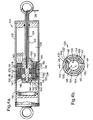
- Damper 100 includes a cylinder 102 containing magnetorheological fluid, a piston assembly 104 slidably mounted for reciprocal movement in cylinder 102 and a plurality of annular flow gaps 106 for effectively increasing a turn-up ratio for a piston assembly of a given length or permitting a smaller piston length for a given turn-up ratio.
- flow gap is used to refer to a fluid flow passage through a damper piston through which fluid is forced to flow by axial movement of the piston within the damper so as to generate a damping force.
- piston assembly 104 divides cylinder 102 into a first chamber 108 positioned on one side of piston assembly 104 and a second chamber 110 positioned on an opposite side of piston assembly 104.
- Piston assembly 104 includes a piston core 112 and a magnet assembly 114.
- Magnet assembly 114 includes a coil 116 mounted on a central portion of piston core 112, flux pole pieces 118 formed by piston core 112 on both sides of coil 116 and a plurality of annular flux rings 120 extending around the circumference of piston core 112.
- Piston assembly 104 also includes the plurality of substantially annular flow gaps 106 positioned between two flux rings or a flux ring and piston core 112.
- Magnetorheological damper 100 also includes a cylindrical rod 122 operatively connected to piston assembly 104 for transmitting axial forces to piston assembly 104.
- Rod 122 also includes a central bore 124 containing electrical leads 126 for delivering electrical power to coil 116.
- a piston bearing 128 is mounted on an outer annular surface of piston assembly 104 for permitting smooth sliding contact along cylinder 102 while creating a fluidic seal between first chamber 108 and second chamber 110.
- magnetorheological fluid present in one of the chambers of cylinder 102 flows through the plurality of substantially annular flow gaps 106 from, for example, second chamber 110 to first chamber 108 as piston assembly 104 moves to the left as shown in FIG. 4A.
- the magnetorheological fluid may be any conventional fluid including magnetic particles, such as iron or iron alloys, which can be controllably suspended within the fluid by controlling a magnetic field across the plurality of substantially annular flow gaps 106 thereby varying the flow characteristics of the fluid through flow gaps 106.
- the electrical current to coil 116 is variably controlled to vary the magnetic field and thus the magnetic flux in flow gaps 106 thereby controlling the flow characteristics of the magnetorheological fluid to achieve a desired damping affect for a given application.
- the plurality of substantially annular flow gaps 106 function to provide an increased damping force when the damper is in the on-state (on-state force) thereby providing an enhanced turn-up ratio while permitting tuning of the force-velocity damping characteristics thereby optimizing damping and providing exceptional control of, for example, vehicle chassis dynamics.
- the MR damper of the present invention more closely approximates the ideal performance and force-velocity characteristics shown in FIG. 1 than the force-velocity characteristics of conventional MR damper designs as shown in FIG. 3.
- the initial on-state force (F init ) at zero velocity is dependent on the yield stress of the MR fluid which in turn depends on the magnetic flux density in the annular flow gap.
- the plurality of substantially annular flow gaps 106 functions to increase the turn-up ratio by increasing the initial on-state force F init and therefore the total on-state F on .
- the plurality of substantially annular flow gaps 106 effectively increase the damping force by increasing the total effective annular flow gap area of a conventional MR damper design.
- This increase in the annular flow gap area in the present damper is achieved without increasing the axial length of the annular flow gap and thus the length of the piston assembly by forming the plurality of annular flow gaps 106 positioned concentrically relative to one another.
- a greater amount of fluid experiences the magnetorheological affect while flowing through a properly designed annular flow gap thereby increasing the damping force for a given piston length.
- the plurality of substantially annular flow gaps 106 includes a first annular flow gap 130 formed between a first flux ring 132 and piston core 112.
- a second flux ring 134 is mounted concentrically around first flux ring 132 to form a second annular flow gap 136 positioned between second flux ring 134 and first flux ring 132.
- FIG. 4A may also include a third flux ring 138 positioned around, and spaced from, second flux ring 134 to form a third annular flow gap 140 positioned between third flux ring 138 and second flux ring 134.
- First, second and third flux rings 132, 134 and 138 are connected to piston core 112 and secured by a first end plate 142 and a second end plate 144 to prevent relative movement so as to maintain the precise radial length of each respective flow gap. Both first and second end plates 142 and 144 are sized to completely cover each respective end face of piston core 112 without hindering flow through the plurality of annular flow gaps 106. First and second end plates 142 and 144 include radial extensions 146 extending radially outward and spaced around the circumference of the respective plate for engaging the plurality of annular flux rings 120.
- radial extensions 146 include grooves 148 for receiving the ends of first, second and third flux rings 132, 134 and 138 so as to secure the flux rings in fixed axial and transverse positions to prevent relative movement thereby maintaining a desired transverse width, i.e., radial length L g in Eq. (1), of first, second and third annular flow gaps 130, 136 and 140.
- First end plate 142 also functions to maximize the magnetic field in the plurality of annular flow gaps 106 by minimizing leakage flux and thereby increasing the initial on-state force F init by functioning as a magnetic isolation barrier between piston core 112 and both rod 122 and cylinder 102.
- first end plate 142 functions to reduce magnetic flux leakage by completely covering the end face of piston core 112, by being formed of a non-magnetic material and by being positioned between rod 122 and piston core 112 so as to isolate rod 122.
- First end plate 142 also functions to maximize flux production by permitting rod 122 to be connected to piston assembly 104 without direct rod intrusion into piston core 112 thereby maximizing the magnetic material of the core.
- Second end plate 144 also effectively functions as a magnetic flux leakage reduction device while securing flux pole pieces 118 and plurality of annular flux rings 120 in position.
- second end plate includes a flat plate 147 and a non-magnetic nut 149. The nut completes covers and threadably engages a threaded boss extending from piston core 112 thereby minimizing leakage from piston core 112.
- First and second end plates 142 and 144 may also include inner annular curved surfaces 150 for smoothly guiding fluid flow into and out of plurality of annular flow gaps 106 thereby enhancing laminar flow and minimizing turbulence through the gaps thus optimizing the magnetorheological effect within the gaps as discussed more fully in co-pending U.S. patent application entitled Magnetorheological Fluid Damper With Optimum Damping noted hereinabove.
- first flux ring 132 and second flux ring 134 each include magnetic flux barriers formed of non-magnetic material and positioned annularly along a central portion of each of the flux rings.
- Magnetic flux barriers 152 function to prevent the lines of flux from traveling axially through first and second flux rings 132 and 134 without extending across third annular flow gap 140. By preventing this flux shunting, magnetic flux barriers 152 function to control the flux flow path to direct lines of flux through third annular flow gap 140 thereby ensuring a desired magnetorheological effect in third annular flow gap 140 and optimizing overall damping.
- Damper 100 of the present invention utilizes the plurality of substantially annular flow gaps 106 to achieve several important advantages.
- the increase in the total effective annular flow gap area using multiple flow gaps relative to a single gap damper results in a higher on-state force and thus a higher turn-up ratio resulting in improved damping over a single tube design for a given piston length.
- the term "annular flow gap area" in the previous sentence refers to the surface area of the walls within the annular flow gap across which the fluid flows.
- the multiple flow gap damper of the present invention permits a piston having a shorter length than a single gap damper piston while achieving the same force specification.
- the multiple flow gap damper of the present invention can significantly reduce piston length by, for example, 30% compared to single gap designs while providing a longer stroke which is advantageous in certain applications.
- the multiple flow gap damper of the present invention results in better linearity during damping which more closely approximates the ideal performance requirements as shown in FIG. 1 by providing a greater number of design variables permitting enhanced tuning capability for controlling force-velocity curves, especially at low and mid-level velocities.
- conventional single gap damper designs only permit the axial length and the radial length of the flow gap to be modified to control the force/velocity characteristics of the damper.
- control over the axial and/or radial length of the gap may be limited by packaging constraints.
- the multiple flow gap damper of the present invention permits the individual dimensions of the flow gaps to be tuned both individually and relative to one another creating numerous possibilities for setting the slope of the curves shown in FIG. 1. Consequently, the present damper enables design optimization for maximum turn-up ratio, improved linearity of damping force response (at higher piston velocities), and tuning (shaping) of the curves at low and medium piston velocities).
- the multiple flow damper of the present invention also achieves optimized damping behavior near zero velocity as indicated in FIG. 1 thereby achieving stiction free behavior in the on-state to minimize harshness.
- This goal was achieved by forcing the force-velocity on-state curve to pass through zero.
- a linear force-velocity curve passing through zero is achieved by using laminar flow of the MR fluid through magnetically substantially neutral flow bypass channels extending through piston assembly 104.
- the initial slope of the force-velocity curve of FIG. 1 is controlled appropriately selecting the cross-sectional area of the bypass channels. For example, as shown in FIG.
- the bypass channels may include at least one of, and preferably both, multiple outer flow bypass channels 154 formed in third flux ring 138 and inner flow bypass channels 156 extending completely through piston assembly 104 and thus formed in piston core 112, and first and second end plates 142 and 144.
- Outer flow bypass channels 154 may be formed with a square or rectangular cross-section while inner flow bypass channels 156 may be formed with round or oval cross-section shapes.
- the flow is substantially through bypass channels 154, 156 with a zero velocity resulting in zero force as the velocity increases substantially above zero, the pressure drop across the bypass channels exceeds the pressure drop due to the magnetorheological affect and the plurality of annular flow gaps 106 so that subsequent force characteristics depend on the magnetorheological characteristics through the flow gaps 106 and thus the dimensions of the flow gaps.
- damper 100 maximizes the active magnetic flux and thus F init by strategically positioning bearing 128.
- bearing 128 is mounted on third flux ring 138 (or whichever is the outermost flux ring) so as to maximize the primary magnetic area in the center of flux ring 138 where the flux is concentrated.
- bearing 128 is positioned at one end of third flux ring 138 axially along piston assembly 104 entirely between an axial center of piston core 112 and first chamber 108.
- bearing 128 may be positioned to the left of center as shown in FIG. 4A. In either offset position, the primary magnetic area of third (or outermost) flux ring 138 is maximized to increase magnetic flux and ultimately the turn-up ratio.
Landscapes
- Engineering & Computer Science (AREA)
- General Engineering & Computer Science (AREA)
- Physics & Mathematics (AREA)
- Electromagnetism (AREA)
- Mechanical Engineering (AREA)
- Fluid-Damping Devices (AREA)
Claims (15)
- Amortisseur, comprenant un cylindre (102) contenant un fluide magnétorhéologique et un assemblage de piston (104) monté coulissant pour un mouvement de va-et-vient dans ledit cylindre afin de former une première chambre (108) positionnée sur un côté dudit assemblage de piston et une deuxième chambre (110) positionnée sur un côté opposé dudit assemblage de piston, ledit assemblage de piston comprenant une pluralité de passages sensiblement annulaires (130, 136, 140) positionnés de manière concentrique les uns par rapport aux autres, chacun de ladite pluralité de passages sensiblement annulaires étant formé entre des surfaces opposées de matériau magnétique, caractérisé en ce que ledit assemblage de piston comprend de plus un assemblage d'aimant (114) adapté pour produire un champ magnétique traversant toute ladite pluralité de passages sensiblement annulaires pour obliger le fluide magnétorhéologique traversant ladite pluralité de passages sensiblement annulaires à subir un effet magnétorhéologique influençant l'écoulement du fluide magnétorhéologique à travers ladite pluralité de passages sensiblement annulaires, chacun de la pluralité de passages sensiblement annulaires permettant un écoulement à travers eux dans les deux sens entre les première et deuxième chambres.
- Amortisseur selon la revendication 1, caractérisé en ce que ladite pluralité de passages sensiblement annulaires comprend deux passages sensiblement annulaires.
- Amortisseur selon la revendication 2, caractérisé en que ledit assemblage de piston comprend de plus une pluralité de bagues magnétiques annulaires (132, 134, 138) positionnées concentriquement afin de former ladite pluralité de passages sensiblement annulaires.
- Amortisseur selon la revendication 3, comprenant de plus une première plaque d'extrémité (142) assujettie à une extrémité dudit assemblage de piston et une deuxième plaque d'extrémité (144) assujettie à une deuxième extrémité dudit assemblage de piston, lesdites première et deuxième plaques d'extrémité étant formées d'un matériau non magnétique et comprenant des extensions radiales (146) connectées à ladite pluralité de bagues magnétiques annulaires.
- Amortisseur selon la revendication 4, caractérisé en ce que chacune desdites extensions radiales comprend des rainures (148) pour accueillir ladite pluralité de bagues magnétiques.
- Amortisseur selon la revendication 3, caractérisé en ce qu'une partie centrale de chacune desdites bagues magnétiques comprend une barrière de flux magnétique (152) formée d'un matériau non magnétique.
- Amortisseur selon la revendication 1, caractérisé en ce que ledit assemblage de piston comprend de plus un palier de piston (128) monté sur ledit assemblage de piston et positionné axialement le long dudit assemblage de piston complètement entre un centre axial dudit assemblage de piston et une desdites première et deuxième chambres.
- Amortisseur selon la revendication 1, caractérisé en ce que ledit assemblage de piston comprend de plus un coeur de piston (112) et une plaque d'extrémité non magnétique (142) connectée audit assemblage de piston, comprenant de plus une tige (122) connectée à ladite plaque d'extrémité non magnétique, ladite plaque d'extrémité non magnétique étant positionnée axialement entre ladite tige et ledit coeur de piston afin d'isoler et de positionner ladite tige à une distance axiale écartée dudit coeur de piston.
- Amortisseur selon la revendication 1, caractérisé en ce que ledit assemblage de piston comprend un coeur de piston (112) et ledit assemblage d'aimant comprend une première bague magnétique (132) positionnée concentriquement autour dudit coeur de piston afin de former un premier (130) de la pluralité de passages annulaires positionné radialement entre ledit coeur de piston et ladite première bague magnétique et comprend de plus une deuxième bague magnétique (134) positionnée concentriquement autour de ladite première bague magnétique afin de former un deuxième (136) de la pluralité de passages annulaires positionné radialement entre ladite première bague magnétique et ladite deuxième bague magnétique.
- Amortisseur selon la revendication 9, caractérisé en ce que ledit assemblage d'aimant comprend de plus une troisième bague magnétique (138) positionnée concentriquement autour de ladite deuxième bague magnétique afin de former un troisième (140) de la pluralité de passages annulaires positionné radialement entre ladite deuxième bague magnétique et ladite troisième bague magnétique.
- Amortisseur selon la revendication 9, comprenant de plus une première plaque d'extrémité (142) assujettie à une première extrémité dudit assemblage de piston et une deuxième plaque d'extrémité (144) assujettie à une deuxième extrémité dudit assemblage de piston, lesdites première et deuxième plaques d'extrémité étant formées d'un matériau non magnétique et comprenant des extensions radiales (146) connectées auxdites premières et deuxièmes bagues magnétiques annulaires.
- Amortisseur selon la revendication 11, caractérisé en ce que chacune desdites extensions radiales comprend des rainures (148) pour accueillir chacune desdites première et deuxième'bagues magnétiques.
- Amortisseur selon la revendication 9, caractérisé en ce qu'une partie centrale de chacune desdites première et deuxième bagues magnétiques comprend une barrière de flux magnétique (152) formée d'un matériau non magnétique.
- Amortisseur selon la revendication 9, caractérisé en ce que ledit assemblage de piston comprend de plus un palier de piston (128) monté sur ledit assemblage de piston et positionné axialement le long dudit assemblage de piston entièrement entre un centre axial dudit assemblage de piston et une desdites première et deuxième chambres.
- Amortisseur selon la revendication 9, caractérisé en ce que ledit assemblage de piston comprend de plus une plaque d'extrémité non magnétique (142) connectée audit assemblage de piston, comprenant de plus une tige (122) connectée à ladite plaque d'extrémité non magnétique, ladite plaque d'extrémité non magnétique étant positionnée axialement entre ladite tige et ledit coeur de piston pour isoler et positionner ladite tige à une distance axiale écartée dudit coeur de piston.
Priority Applications (2)
| Application Number | Priority Date | Filing Date | Title |
|---|---|---|---|
| DE2001623769 DE60123769T2 (de) | 2001-06-19 | 2001-06-19 | Magnetorheologische Flüssigkeitsdämpfer mit Mehrfach- Ringströmungsspalten |
| EP01202374A EP1270989B1 (fr) | 2001-06-19 | 2001-06-19 | Amortisseur à fluide magnétorhéologique avec de multiples passages annulaires |
Applications Claiming Priority (1)
| Application Number | Priority Date | Filing Date | Title |
|---|---|---|---|
| EP01202374A EP1270989B1 (fr) | 2001-06-19 | 2001-06-19 | Amortisseur à fluide magnétorhéologique avec de multiples passages annulaires |
Publications (2)
| Publication Number | Publication Date |
|---|---|
| EP1270989A1 EP1270989A1 (fr) | 2003-01-02 |
| EP1270989B1 true EP1270989B1 (fr) | 2006-10-11 |
Family
ID=8180507
Family Applications (1)
| Application Number | Title | Priority Date | Filing Date |
|---|---|---|---|
| EP01202374A Expired - Lifetime EP1270989B1 (fr) | 2001-06-19 | 2001-06-19 | Amortisseur à fluide magnétorhéologique avec de multiples passages annulaires |
Country Status (2)
| Country | Link |
|---|---|
| EP (1) | EP1270989B1 (fr) |
| DE (1) | DE60123769T2 (fr) |
Families Citing this family (15)
| Publication number | Priority date | Publication date | Assignee | Title |
|---|---|---|---|---|
| US7354363B2 (en) * | 2004-05-18 | 2008-04-08 | Dayco Products, Llc | Magnetorheological fluid V-ribbed belt tensioner with through shaft |
| DE102007013916B4 (de) | 2007-03-20 | 2011-06-22 | Feinmess Suhl GmbH, 98527 | Konturenmessvorrichtung |
| US8051961B2 (en) * | 2007-10-30 | 2011-11-08 | Honda Motor Co., Ltd. | Magneto-rheological damper |
| WO2010020425A1 (fr) * | 2008-08-22 | 2010-02-25 | Inventus Engineering Gmbh | Dispositif comportant un fluide magnétorhéologique |
| DE102010050597B4 (de) * | 2010-11-05 | 2013-01-10 | Seuffer Gmbh & Co.Kg | Steuerbare Dämpfungsvorrichtung |
| CN103032511B (zh) * | 2013-01-06 | 2015-03-11 | 谢宁 | 组合活塞单出杆磁流变阻尼器 |
| CN106065916B (zh) * | 2016-08-08 | 2018-10-09 | 华南理工大学 | 一种内置蹄形铁芯的强阻尼磁流变液减震器与方法 |
| CN107313644B (zh) * | 2017-07-13 | 2023-06-16 | 柳州东方工程橡胶制品有限公司 | 一种大承载力永磁调节式磁流变阻尼器 |
| CN108591345B (zh) * | 2018-05-14 | 2020-01-10 | 西安交通大学 | 一种双筒壁的高磁场利用率磁流变阻尼器 |
| CN108547909A (zh) * | 2018-06-06 | 2018-09-18 | 广州大学 | 一种双向剪切型磁流变脂阻尼器 |
| CN108953467B (zh) * | 2018-09-23 | 2023-06-20 | 华东交通大学 | 一种具有串联液流通道的阻尼间隙可调式磁流变阻尼器 |
| CN109236936B (zh) * | 2018-11-11 | 2023-12-22 | 华东交通大学 | 一种采用弹性金属波纹管进行密封的磁流变阻尼器 |
| CN115013469A (zh) * | 2022-06-09 | 2022-09-06 | 北京金茂人居环境科技有限公司 | 径向磁流变阻尼宽频隔振器 |
| CN115962245B (zh) * | 2022-12-09 | 2024-10-22 | 上海理工大学 | 一种阻尼间隙长度自适应调整的磁流变剪切增稠阻尼器 |
| CN120701691B (zh) * | 2025-08-27 | 2025-10-28 | 上海新纪元机器人有限公司 | 电磁力变间隙磁流变阻尼器 |
Citations (1)
| Publication number | Priority date | Publication date | Assignee | Title |
|---|---|---|---|---|
| DE19820570A1 (de) * | 1998-05-08 | 1999-11-11 | Schenck Ag Carl | Schwingungsdämpfer auf Basis elektrorheologischer und/oder magnetorheologischer Flüssigkeiten |
Family Cites Families (5)
| Publication number | Priority date | Publication date | Assignee | Title |
|---|---|---|---|---|
| DE68917370T2 (de) * | 1988-05-13 | 1995-03-30 | Toa Nenryo Kogyo Kk | Dämpfungsvorrichtung für eine rotierende Welle. |
| US5014829A (en) * | 1989-04-18 | 1991-05-14 | Hare Sr Nicholas S | Electro-rheological shock absorber |
| US5277281A (en) | 1992-06-18 | 1994-01-11 | Lord Corporation | Magnetorheological fluid dampers |
| DE4433056C2 (de) * | 1994-09-16 | 1998-01-29 | Mannesmann Sachs Ag | Schwingungsdämpfer für Kraftfahrzeuge |
| US6095486A (en) | 1997-03-05 | 2000-08-01 | Lord Corporation | Two-way magnetorheological fluid valve assembly and devices utilizing same |
-
2001
- 2001-06-19 EP EP01202374A patent/EP1270989B1/fr not_active Expired - Lifetime
- 2001-06-19 DE DE2001623769 patent/DE60123769T2/de not_active Expired - Lifetime
Patent Citations (1)
| Publication number | Priority date | Publication date | Assignee | Title |
|---|---|---|---|---|
| DE19820570A1 (de) * | 1998-05-08 | 1999-11-11 | Schenck Ag Carl | Schwingungsdämpfer auf Basis elektrorheologischer und/oder magnetorheologischer Flüssigkeiten |
Also Published As
| Publication number | Publication date |
|---|---|
| DE60123769T2 (de) | 2007-09-06 |
| EP1270989A1 (fr) | 2003-01-02 |
| DE60123769D1 (de) | 2006-11-23 |
Similar Documents
| Publication | Publication Date | Title |
|---|---|---|
| US6279701B1 (en) | Magnetorheological fluid damper with multiple annular flow gaps | |
| US6390252B1 (en) | Magnetorheological fluid damper with optimum damping | |
| EP1270989B1 (fr) | Amortisseur à fluide magnétorhéologique avec de multiples passages annulaires | |
| US11015672B2 (en) | Smart fluid damper | |
| EP1437526B1 (fr) | Piston et amortisseur magnétorhéologique | |
| US6019201A (en) | Magneto-rheological fluid damper | |
| US6336535B1 (en) | Magneto-rheological damper with dual flux ring spacer | |
| US7958979B2 (en) | Variable damper | |
| EP2504606B1 (fr) | Ensemble amortisseur à solénoïde bistable | |
| US7364022B2 (en) | Controllable magneto-rheological fluid devices for motion-damping | |
| US5632361A (en) | Vibration damper, in particular for motor vehicles | |
| US6471018B1 (en) | Magneto-rheological fluid device | |
| US6419058B1 (en) | Magnetorheological damper with piston bypass | |
| EP1016806A2 (fr) | Dispositifs à fluide magnétorhéologique | |
| US20120186921A1 (en) | Shock Absorber for a Bicycle | |
| US20020084157A1 (en) | Magneto-rheological damping valve using laminated construction | |
| US20040118646A1 (en) | Magnetorheological damper assembly and piston | |
| US6637560B2 (en) | Vehicle damper assembly and method of modulating fluid flow | |
| US5551540A (en) | Vibration damper and a vibration damper with a valve actuation device | |
| US7753180B2 (en) | Magnetorheological piston having a bypass passageway | |
| KR100445988B1 (ko) | 자기유변유체를 이용한 쇽 업소버 | |
| KR100445987B1 (ko) | 자기유변유체를 이용한 쇽 업소버 | |
| CN118517490A (zh) | 一种阻尼力不对称的磁流变减震器 | |
| CA2984533C (fr) | Amortisseur a fluide intelligent |
Legal Events
| Date | Code | Title | Description |
|---|---|---|---|
| PUAI | Public reference made under article 153(3) epc to a published international application that has entered the european phase |
Free format text: ORIGINAL CODE: 0009012 |
|
| AK | Designated contracting states |
Kind code of ref document: A1 Designated state(s): AT BE CH CY DE DK ES FI FR GB GR IE IT LI LU MC NL PT SE TR |
|
| AX | Request for extension of the european patent |
Free format text: AL;LT;LV;MK;RO;SI |
|
| 17P | Request for examination filed |
Effective date: 20030702 |
|
| AKX | Designation fees paid |
Designated state(s): DE FR GB IT |
|
| 17Q | First examination report despatched |
Effective date: 20041228 |
|
| GRAP | Despatch of communication of intention to grant a patent |
Free format text: ORIGINAL CODE: EPIDOSNIGR1 |
|
| GRAS | Grant fee paid |
Free format text: ORIGINAL CODE: EPIDOSNIGR3 |
|
| GRAA | (expected) grant |
Free format text: ORIGINAL CODE: 0009210 |
|
| AK | Designated contracting states |
Kind code of ref document: B1 Designated state(s): DE FR GB IT |
|
| PG25 | Lapsed in a contracting state [announced via postgrant information from national office to epo] |
Ref country code: IT Free format text: LAPSE BECAUSE OF FAILURE TO SUBMIT A TRANSLATION OF THE DESCRIPTION OR TO PAY THE FEE WITHIN THE PRESCRIBED TIME-LIMIT;WARNING: LAPSES OF ITALIAN PATENTS WITH EFFECTIVE DATE BEFORE 2007 MAY HAVE OCCURRED AT ANY TIME BEFORE 2007. THE CORRECT EFFECTIVE DATE MAY BE DIFFERENT FROM THE ONE RECORDED. Effective date: 20061011 |
|
| REG | Reference to a national code |
Ref country code: GB Ref legal event code: FG4D |
|
| REF | Corresponds to: |
Ref document number: 60123769 Country of ref document: DE Date of ref document: 20061123 Kind code of ref document: P |
|
| ET | Fr: translation filed | ||
| PLBE | No opposition filed within time limit |
Free format text: ORIGINAL CODE: 0009261 |
|
| STAA | Information on the status of an ep patent application or granted ep patent |
Free format text: STATUS: NO OPPOSITION FILED WITHIN TIME LIMIT |
|
| 26N | No opposition filed |
Effective date: 20070712 |
|
| GBPC | Gb: european patent ceased through non-payment of renewal fee |
Effective date: 20070619 |
|
| PG25 | Lapsed in a contracting state [announced via postgrant information from national office to epo] |
Ref country code: GB Free format text: LAPSE BECAUSE OF NON-PAYMENT OF DUE FEES Effective date: 20070619 |
|
| PGFP | Annual fee paid to national office [announced via postgrant information from national office to epo] |
Ref country code: IT Payment date: 20100624 Year of fee payment: 10 |
|
| PG25 | Lapsed in a contracting state [announced via postgrant information from national office to epo] |
Ref country code: IT Free format text: LAPSE BECAUSE OF NON-PAYMENT OF DUE FEES Effective date: 20110619 |
|
| REG | Reference to a national code |
Ref country code: FR Ref legal event code: PLFP Year of fee payment: 16 |
|
| REG | Reference to a national code |
Ref country code: FR Ref legal event code: PLFP Year of fee payment: 17 |
|
| REG | Reference to a national code |
Ref country code: FR Ref legal event code: CA Effective date: 20171124 Ref country code: FR Ref legal event code: TP Owner name: BWI COMPANY LIMITED S.A., LU Effective date: 20171124 |
|
| REG | Reference to a national code |
Ref country code: FR Ref legal event code: PLFP Year of fee payment: 18 |
|
| PGFP | Annual fee paid to national office [announced via postgrant information from national office to epo] |
Ref country code: DE Payment date: 20180605 Year of fee payment: 18 |
|
| PGFP | Annual fee paid to national office [announced via postgrant information from national office to epo] |
Ref country code: FR Payment date: 20190510 Year of fee payment: 19 |
|
| REG | Reference to a national code |
Ref country code: DE Ref legal event code: R119 Ref document number: 60123769 Country of ref document: DE |
|
| REG | Reference to a national code |
Ref country code: DE Ref legal event code: R081 Ref document number: 60123769 Country of ref document: DE Owner name: BWI COMPANY LIMITED S.A., LU Free format text: FORMER OWNER: DELPHI TECHNOLOGIES, INC., TROY, MICH., US Ref country code: DE Ref legal event code: R082 Ref document number: 60123769 Country of ref document: DE |
|
| PG25 | Lapsed in a contracting state [announced via postgrant information from national office to epo] |
Ref country code: DE Free format text: LAPSE BECAUSE OF NON-PAYMENT OF DUE FEES Effective date: 20200101 |
|
| PG25 | Lapsed in a contracting state [announced via postgrant information from national office to epo] |
Ref country code: FR Free format text: LAPSE BECAUSE OF NON-PAYMENT OF DUE FEES Effective date: 20200630 |