EP1271002B1 - Stufenloses Getriebe und Riemenscheibe - Google Patents
Stufenloses Getriebe und Riemenscheibe Download PDFInfo
- Publication number
- EP1271002B1 EP1271002B1 EP01202334A EP01202334A EP1271002B1 EP 1271002 B1 EP1271002 B1 EP 1271002B1 EP 01202334 A EP01202334 A EP 01202334A EP 01202334 A EP01202334 A EP 01202334A EP 1271002 B1 EP1271002 B1 EP 1271002B1
- Authority
- EP
- European Patent Office
- Prior art keywords
- wall
- axial
- radial
- transmission according
- foot part
- Prior art date
- Legal status (The legal status is an assumption and is not a legal conclusion. Google has not performed a legal analysis and makes no representation as to the accuracy of the status listed.)
- Expired - Lifetime
Links
Images

Classifications
-
- F—MECHANICAL ENGINEERING; LIGHTING; HEATING; WEAPONS; BLASTING
- F16—ENGINEERING ELEMENTS AND UNITS; GENERAL MEASURES FOR PRODUCING AND MAINTAINING EFFECTIVE FUNCTIONING OF MACHINES OR INSTALLATIONS; THERMAL INSULATION IN GENERAL
- F16H—GEARING
- F16H55/00—Elements with teeth or friction surfaces for conveying motion; Worms, pulleys or sheaves for gearing mechanisms
- F16H55/32—Friction members
- F16H55/52—Pulleys or friction discs of adjustable construction
- F16H55/56—Pulleys or friction discs of adjustable construction of which the bearing parts are relatively axially adjustable
-
- F—MECHANICAL ENGINEERING; LIGHTING; HEATING; WEAPONS; BLASTING
- F16—ENGINEERING ELEMENTS AND UNITS; GENERAL MEASURES FOR PRODUCING AND MAINTAINING EFFECTIVE FUNCTIONING OF MACHINES OR INSTALLATIONS; THERMAL INSULATION IN GENERAL
- F16H—GEARING
- F16H63/00—Control outputs from the control unit to change-speed- or reversing-gearings for conveying rotary motion or to other devices than the final output mechanism
- F16H63/02—Final output mechanisms therefor; Actuating means for the final output mechanisms
- F16H63/04—Final output mechanisms therefor; Actuating means for the final output mechanisms a single final output mechanism being moved by a single final actuating mechanism
- F16H63/06—Final output mechanisms therefor; Actuating means for the final output mechanisms a single final output mechanism being moved by a single final actuating mechanism the final output mechanism having an indefinite number of positions
- F16H63/065—Final output mechanisms therefor; Actuating means for the final output mechanisms a single final output mechanism being moved by a single final actuating mechanism the final output mechanism having an indefinite number of positions hydraulic actuating means
Definitions
- the invention relates to a continuously variable transmission, in particular a pulley design therefor, as defined by the features of the preamble of claim 1.
- Transmissions and pulleys of such kind are generally known and used.
- One such transmission and pulley is disclosed in EP-A-0 560 427, which is considered an improvement over US-A 3 948 111.
- the pulley of the latter document comprises a separate seal element or piston incorporating a resilient hinge between two concentric cylinder walls that are part of a pressure chamber.
- Such seal element and such hinging feature are of vital importance for the functioning of a pulley, and therewith of the entire transmission.
- Pressure chambers usually hydraulic, are incorporated for urging a pulley disc in axial direction so as to effect adequate clamping for and a radial shifting of a belt or other transmission element located between the two discs a pulley.
- problems may arise regarding the degree of stability of the pulley, and deformations can be observed which may affect the action of the transmission. It was the object of the invention according to EP-A-0 560 427 to provide an improved pulley, in particular a piston therefor, suitable for relatively high powers and whose stability and resistance to permanent deformation were improved.
- the pulley according to EP-A-0 560 427 was characterised the presence of a resilient hinge in the wall material of the pressure chamber of the cylinder/piston means, with the result that, under the influence of any momentary relatively high pressure, the relevant wall can locally absorb forces in an elastic manner, in particular if the transmission transmits a high torque.
- the resilient hinge is in the known construction realised by a locally thinner section of the wall, in particular by a local recess therein. The absorption of the forces in this prior art construction is effected at a predetermined, known position of the resilient hinge, and in a predictable manner. In this proposition, the forces are absorbed locally by elastic deformation and by controlled expansion of the wall around the resilient hinge.
- the forces are to a large extent absorbed in an elastic manner by the wall with the resilient hinge, they are passed on to the supporting part, for example the supporting shaft on which the displaceable disc is mounted, in very much reduced form, as a result of which, under heavy load, clamping and deformation of the relevant part, in particular the sleeve of the moving sheave, forming a shaft, is prevented.
- the stability and the resistance to permanent deformation, as well as the action of the transmission are therefore greatly improved.
- the fixed connection is designed as a force fit, which has the advantage that, on the one hand, a fixed connection is achieved by combining the force fit and the closely adjacent resilient hinge, while, on the other hand, a certain degree of elastic deformation is possible without this resulting in permanent deformation.
- a hinge section is created in the piston, defined by the transition from wall to foot part.
- the construction with the foot part has for advantages that at the radial inner end portion of the axial outer side of the wall a relatively large section is available for taking up tensile stresses, thus creating a lower risk of exceeding the yield stress of the wall material and therewith lasting deformation.
- the axial end of the foot part away from radial extending wall is loaded by such resulting forces in a favourable manner, so that the press fit of the wall, in particular this foot part, has a high chance of being maintained during life time of the construction.
- Another advantage is that in principle no, at least significantly less hammering of the axial supporting face of the shaft will take place by the wall under changes in pressure load, since the hinging movement of the wall is displaced towards the region of the transition and only the foot part is in contact with the shaft.
- the latter is in the present construction in particular of significance, since the supporting face in this design functions as a positioning element for the wall at assembly and during operation.
- Such design is alternatively denoted positive connection of the wall and obviates the necessity of an additional recess in the shaft for staking the wall, thereby reducing manufacturing cost.
- securing the wall position by staking of the foot part on to said shaft part is omitted.
- reference to an axially outward direction or vice versa shall mean directed away from the disc 5 and vice versa respectively.
- reference to radial outward direction and vice verse shall mean directed away from the central axis of the relevant part and vice versa respectively.
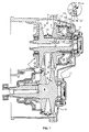
- FIG 1 diagrammatically shows a continuously variable transmission 1, which is illustrated in part.
- the transmission 1 comprises a primary shaft 2, on which a primary pulley 3 is fitted in the form of discs 4 and 5, disc 5 being axially displaceable along the shaft 2 in a manner still to be specified.
- the transmission 1 furthermore comprises a secondary shaft 6, on which a secondary pulley 7 is fitted with discs 8 and 9, disc 8 of which may be displaced along the shaft 6.
- An endless drive belt, chain or belt 10 has been fitted around the pulleys 3 and 7, the path of the belt 10 between the sets of discs 4, 5; 8, 9 being variable and dependent on the axial position of the displaceable discs 5 and 8.
- the primary shaft 2 is connected in a manner known per se to an engine (not shown) and the secondary shaft 6 is connected to the wheels of a vehicle (not shown)
- the axially displaceable disc 5 comprises cylinder/piston means 12 which generally comprise at least one pressure chamber 14
- the transmission 1 comprises cylinder/piston means which comprise a further, second pressure chamber 13.
- the chamber 25 is unpressurised. A medium under pressure is supplied to and discharged from, in this case, both the chambers 13 and 14 through suitable passages 15 and 16, in order thereby to affect the axial position of disc 5.
- the pressure chamber 13 comprises essentially radially directed walls 18 and 24, in addition to cylindrical wall 19 and shaft 2.
- Wall 17 is displaceable between wall or hub 20 and cylinder wall 21 of the disc 5.
- wall 17 rests against the wall 19, while one end of wall 18 seals displaceable on cylindrical wall 19 and, in this embodiment, is connected by its other, circled end to hub 20 of the disc 5.
- Wall 18 is also referred to as the piston 18 of a cylinder piston means.
- the enlarged detail shows that, at the position of the point where the walls 18 and 20 are connected to one another, there is in the prior art construction a resilient hinge 22 which in this prior art design has the form of a recess 22A outside the wall and a recess 22B at the inner diameter and inner side of the wall.
- a resilient hinge 22 which in this prior art design has the form of a recess 22A outside the wall and a recess 22B at the inner diameter and inner side of the wall.
- wall 18 can deform flexibly.
- items 18 and 20 are represented in a position at some distance from wall 24.
- connection between the items 18 and 20 at the side closest to the construction 22A, 22B is effected by means of a force fit.
- the force fit is preferably of such elastic design that the narrow clearance of hub or wall 20 is maintained and wall 20 remains displaceable relative to the shaft 2.
- Figure 2 by part of a transmission section and mirrored relative to figure 1, shows the piston 18 according to the invention incorporated in a pulley, in casu the primary pulley.
- the wall 18 according to the invention has a foot part 30, which abuts a supporting face in the form of radial wall part 26 of a shaft, in casu embodied the sleeve or hub 20 of disc 5. It shows the inner face or side 27 and the outer face 28 of the wall 18 to be smoothly extending as seen in cross section, at least to the radial inner portion thereof, i.e. without interrupting recesses like recesses 22A and 22B of the prior art design.
- Figure 3 in detail represents the piston according to the invention, with a curvedly shaped transition, or hinging section 29 between the inner wall side 27 and the foot part 30.
- a localised hinging at the location of the transition of the wall 18 and the foot part 30 it is suggested to locally adopt the smallest width of the wall as measured perpendicular to a radially and tangentially extending centre plane of the wall and/or by providing the inner wall side 27 at the location of the hinging transition section 29 with a relatively small radius of curvature.
- curvature of the transition section 29 has a radius of about 0.8 mm, which is within a preferred range from 0.7 mm to 1.25 mm.
- the foot part 30 has a length of more than one and a half times, the thickness occurring over the largest portion of the wall 18. More preferably the foot part 30 should extend axially as long as possible, e.g. over the entire axial length of the axial stroke of the neighbouring wall 17, i.e. virtually over the entire axial length of the pressure chamber 14. Thus the foot part 30 would than bear wall 17.
- a radially inner end of the foot part 30 has a recess 32 of small radial extension starting at an axial point 31. Point 31 is preferably located to the left of the transition section 29 as depicted in figures 2 and 3, i.e. axially outward therefrom.
- a press fit section 34 of the foot part of the piston 18 is located to axially towards the disc 5 to the right of point 31 in figure 3, i.e. axially inward.
- the recess 32 further aids in determining the localisation of the hinging section of the wall 18, 24, i.e. in a section away from the section where in accordance with an aim of the invention, a stable and unaffected force fit of the wall is achieved, i.e. in the area at the radial inner part of the foot part 30, where the foot 30 is force fitted to the shaft 20.
- the thickness of the foot 30 is slightly smaller than the radial height of the wall 26, thus minimising the effect of any residual hammering, on the wall 26 which might e.g. occur when the axial length of the foot part 30 is kept to a minimum and when the materials applied are qualitatively not of the most expensive kind.
- the effect includes the risk of material particles coming loose in the relevant pressure chamber, which might severely hamper if not damage the functioning of the piston/cylinder assembly, and therewith of the transmission.
- such smaller height also has a function in allowing the largest possible stroke of e.g. sleeve 20, i.e. allowing an overlap thereof with the foot part 30, without there being any chance of mutual contact therewith at the abutting face.
- the foot part 30 may further be provided with a wall part 33 preferably extending under an angle ⁇ between 25 and 40 degrees with the press fit section 34 forming a small recess therein in the general square shape of the foot part 30 and promoting optimal press fitting by allowing for a possible transition edge in the shaft 2.
- a radial innermost curvature on the outer wall side 28 transits to a lowest portion of the same side 28, extending straight and square relative to the foot part 30, at a radial location above the foot part 30, preferably at a distance less than the thickness of the wall 18.
- the piston may favourably be produced by sheet metal forming processes.
Landscapes
- Engineering & Computer Science (AREA)
- General Engineering & Computer Science (AREA)
- Mechanical Engineering (AREA)
- Transmissions By Endless Flexible Members (AREA)
- Pulleys (AREA)
Claims (16)
- Stufenloses Getriebe (1), insbesondere Riemenscheibe dafür, mit einem Satz von Riemenscheiben (3, 7), die jeweils mit einem Satz von Scheiben (4, 5; 8, 9) versehen und auf einer Primär- (2) oder einer Sekundär- (6) Welle des Getriebes angebracht sind, wobei mindestes eine Scheibe (5; 8) axial verschiebbar und mit Zylinder-/Kolben-Mitteln (12) versehen ist, wobei die Zylinder-/Kolben-Mittel (12) mindestens eine Druckkammer (13) mit radialen Wänden (5, 17, 18, 24) und konzentrischen Zylinderwänden (2, 20, 19, 21) umfassen und mindestens eine der radialen Wände (18) der Druckkammer mittels einer unbeweglichen Passung, radial entweder an einem Hülsenteil (20) einer Scheibe (5) oder einem Teil der Welle (2) und axial an einem Schulterteil (26) des Hülsenteils (20) bzw. der Welle (2), an einer der konzentrischen Zylinderwände (20) befestigt ist, wobei die Wand (18) in der Nähe der Passung mit einem elastischen Gelenkmerkmal hergestellt ist, dadurch gekennzeichnet, dass das elastische Gelenkmerkmal der Wand (18) dadurch realisiert ist, dass ein hülsenförmiges Fußteil (30), in erster Linie axial vorragend bezüglich eines unteren Teils der Wand (18) und integral damit, eingebaut ist und sich eine axiale Wandfläche (28) der Wand (18) ununterbrochen stetig nach oben bis zum radial inneren Durchmesser und eine andere axiale Wandfläche (27) der Wand (18) ununterbrochen und stetig radial nach innen zu einem Übergangsabschnitt (29) zwischen dem sich in erster Linie radial erstreckenden Wandteil und dem sich in erster Line axial erstreckenden Fußteil (30) davon erstreckt.
- Getriebe nach Anspruch 1, dadurch gekennzeichnet, dass sich der Fußteil (30) von dem sich radial erstreckenden Wandteil axial zu einer Scheibe (5) einer Riemenscheibe erstreckt.
- Getriebe nach Anspruch 1 oder 2, dadurch gekennzeichnet, dass die Dicke des Fußteils (30) in Radialrichtung im Wesentlichen einer Nenndicke des sich radial erstreckenden Wandteils der Wand (18) in Axialrichtung entspricht.
- Getriebe nach einem der vorhergehenden Ansprüche, dadurch gekennzeichnet, dass die Axiallänge des Fußteils (30), gemessen an seiner radialen Innenseite, größer ist als das Eineinhalbfache einer Nenndicke des sich radial erstreckenden Wandteils (18) in Axialrichtung.
- Getriebe nach einem der vorhergehenden Ansprüche, dadurch gekennzeichnet, dass eine Endfläche des Fußteils (30), die von dem sich radial erstreckenden Wandteil axial nach innen zu einer Scheibe (5) der Riemenscheibe gerichtet ist, passgenau an eine Stützfläche (26) oder an einen Schulterteil in Form eines sich radial nach außen erstreckenden Wandteils der Welle der Hülse (2, 20) anstößt.
- Getriebe nach dem vorhergehenden Anspruch, dadurch gekennzeichnet, dass die radiale Höhe des Fußteils (30) kleiner ist als die der Stützfläche (26) der Welle der Hülse (2, 20).
- Getriebe nach einem der vorhergehenden Ansprüche, dadurch gekennzeichnet, dass der Fußteil (30) an der radial inneren und axial äußeren Seite mit einer Aussparung (32) versehen ist, die vorzugsweise weitgehend rechteckig ausgebildet und deren radiale Erstreckung vorzugsweise klein, aber wahrnehmbar ist und die an einer Stelle beginnt, die, mit Blickrichtung von der axialen Wandfläche (27) zur anderen axialen Wandfläche (28), axial nach außen hinter dem Übergang (29) liegt.
- Getriebe nach einem der vorhergehenden Ansprüche, dadurch gekennzeichnet, dass ein Teil des sich radial erstreckenden Wandteils der Wand (18), zumindest in der Nähe des Übergangs (29) von dem sich radial erstreckenden Wandteil zum Fußteil (30), in einer axialen Dicke hergestellt ist, die kleiner ist als eine Nenndicke des sich radial erstreckenden Wandteils der Wand (18) in Axialrichtung, jedoch vorzugsweise größer als Dreiviertel der axialen Nenndicke ist.
- Getriebe nach dem vorhergehenden Anspruch, dadurch gekennzeichnet, dass die kleinere axiale Dicke dadurch realisiert wird, dass die stetig geformte axiale Wandfläche (27) und die andere axiale Wandfläche (28) der Wand (18) etwas zueinander konvergieren.
- Getriebe nach einem der beiden vorhergehenden Ansprüche, dadurch gekennzeichnet, dass eine kleinste axiale Dicke der Wand (18) am Übergangsabschnitt (29) realisiert ist, der dadurch vorzugsweise stetig gekrümmt vorgesehen ist.
- Getriebe nach einem der vorhergehenden Ansprüche, dadurch gekennzeichnet, dass die radial innere Seite des Fußteils (30) an einem axialen Ende davon, das zur axial verschiebbaren Scheibe (5) weist, über eine radiale Strecke von ca. 1 mm ausgespart ist, vorzugsweise derart, dass die sich ergebende Aussparung durch einen Wandteil (33) definiert wird, der sich in einem Winkel von bis zu 40 Grad mit allgemeiner axialer Richtung des Fußteils (30) teilweise in radialer Richtung erstreckt.
- Getriebe nach einem der vorhergehenden Ansprüche, dadurch gekennzeichnet, dass der Übergangsabschnitt (29) in einer Krümmung mit einem Krümmungsradius von 0,5 mm oder darüber, aber unter 1,5 mm hergestellt ist.
- Getriebe nach einem der vorhergehenden Ansprüche, dadurch gekennzeichnet, dass der sich radial erstreckende Wandteil der Wand (18) in einer radial nach außen verlaufenden Richtung vom Fußteil (30) davon über einen wesentlichen Teil seiner radialen Höhe zur axial verschiebbaren Scheibe (5) der Riemenscheibe geneigt ist, und des Weiteren über einen wesentlichen Teil seiner radialen Höhe von der Scheibe (5) weg geneigt ist, wodurch sich der Wandteil am letzteren wesentlichen Teil davon nicht über den Übergangsabschnitt (29) hinaus von der Scheibe (5) weg erstreckt.
- Getriebe nach dem vorhergehenden Anspruch, dadurch gekennzeichnet, dass sich der Fußteil (30) axial bis zu einer Stelle in der Axialerstreckung einer radialen äußeren Aussparung (35) in der Wand (18) zur Aufnahme eines Dichtungsrings erstreckt und in Axialrichtung an einer Stelle in der Axialerstreckung der axialen Wandfläche (27) endet.
- Getriebe nach einem der vorhergehenden Ansprüche, dadurch gekennzeichnet, dass sich die andere axiale Wandfläche (28) der Wand (18) in radial nach innen verlaufender Richtung weiter bis zu über der Höhe des radialen Außenumfangs des Fußteils (30) hinaus erstreckt.
- Getriebe nach einem der vorhergehenden Ansprüche, dadurch gekennzeichnet, dass der Außenumfang der Welle der Hülse (2, 20) an der Stelle, an der die Wand (18) angebracht ist, über die Länge des Fußteils (30) einen im Wesentlichen gleichmäßigen Durchmesser aufweist.
Priority Applications (5)
| Application Number | Priority Date | Filing Date | Title |
|---|---|---|---|
| EP01202334A EP1271002B1 (de) | 2001-06-18 | 2001-06-18 | Stufenloses Getriebe und Riemenscheibe |
| AT01202334T ATE279672T1 (de) | 2001-06-18 | 2001-06-18 | Stufenloses getriebe und riemenscheibe |
| DE60106414T DE60106414T2 (de) | 2001-06-18 | 2001-06-18 | Stufenloses Getriebe und Riemenscheibe |
| JP2002147002A JP2003014065A (ja) | 2001-06-18 | 2002-05-22 | 連続可変トランスミッション及びプーリ |
| US10/173,109 US6962542B2 (en) | 2001-06-18 | 2002-06-18 | Continuously variable transmission and pulley |
Applications Claiming Priority (1)
| Application Number | Priority Date | Filing Date | Title |
|---|---|---|---|
| EP01202334A EP1271002B1 (de) | 2001-06-18 | 2001-06-18 | Stufenloses Getriebe und Riemenscheibe |
Publications (2)
| Publication Number | Publication Date |
|---|---|
| EP1271002A1 EP1271002A1 (de) | 2003-01-02 |
| EP1271002B1 true EP1271002B1 (de) | 2004-10-13 |
Family
ID=8180496
Family Applications (1)
| Application Number | Title | Priority Date | Filing Date |
|---|---|---|---|
| EP01202334A Expired - Lifetime EP1271002B1 (de) | 2001-06-18 | 2001-06-18 | Stufenloses Getriebe und Riemenscheibe |
Country Status (5)
| Country | Link |
|---|---|
| US (1) | US6962542B2 (de) |
| EP (1) | EP1271002B1 (de) |
| JP (1) | JP2003014065A (de) |
| AT (1) | ATE279672T1 (de) |
| DE (1) | DE60106414T2 (de) |
Families Citing this family (7)
| Publication number | Priority date | Publication date | Assignee | Title |
|---|---|---|---|---|
| DE102005026616A1 (de) * | 2005-06-09 | 2006-12-14 | Zf Friedrichshafen Ag | Stufenloses Automatgetriebe, insbesondere Umschlingungsgetriebe, und Verfahren zur Montage des Variators des Getriebes in das Gehäuse |
| JP4999770B2 (ja) * | 2008-04-22 | 2012-08-15 | 本田技研工業株式会社 | ベルト式無段変速機 |
| JP5704230B2 (ja) * | 2011-03-31 | 2015-04-22 | トヨタ自動車株式会社 | ベルト式無段変速機 |
| JP6324137B2 (ja) * | 2014-03-24 | 2018-05-16 | ジヤトコ株式会社 | シール機構付き車両用無段変速機 |
| US11125306B2 (en) * | 2017-02-20 | 2021-09-21 | Unipres Corporation | Dividing wall for primary pulley in belt-type continuously variable transmission |
| US11031744B1 (en) * | 2019-05-23 | 2021-06-08 | National Technology & Engineering Solutions Of Sandia, Llc | Belt structures for rotary electrical contact device |
| MX2025000837A (es) * | 2024-01-23 | 2025-08-01 | Polaris Inc | Transmision mecanica continuamente variable asistida |
Family Cites Families (12)
| Publication number | Priority date | Publication date | Assignee | Title |
|---|---|---|---|---|
| US3948111A (en) | 1970-11-27 | 1976-04-06 | P.I.V. Antrieb Werner Reimers Kg | Cylinder/piston aggregate on a rotating shaft |
| US4713041A (en) * | 1986-09-15 | 1987-12-15 | Ford Motor Company | Non-lubricated drive belt system for a continually variable transmission |
| JP2662961B2 (ja) * | 1987-12-23 | 1997-10-15 | 富士重工業株式会社 | 無段変速機のプーリ |
| JPH0434548U (de) * | 1990-07-19 | 1992-03-23 | ||
| US5182968A (en) * | 1991-10-16 | 1993-02-02 | Borg-Warner Automotive Transmission & Engine Components Corporation | Force ratio control of continuously variable transmissions |
| NL9200428A (nl) * | 1992-03-09 | 1993-10-01 | Doornes Transmissie Bv | Poelie. |
| JP3055747B2 (ja) * | 1993-07-27 | 2000-06-26 | 富士重工業株式会社 | ベルト式無段変速機のプーリ装置 |
| US5628700A (en) * | 1994-06-27 | 1997-05-13 | Nissan Moter Co, Ltd. | Pulley device for continuously variable transmission |
| NL1000932C2 (nl) * | 1995-08-04 | 1997-02-06 | Doornes Transmissie Bv | Poelie. |
| NL1001756C2 (nl) * | 1995-11-28 | 1997-05-30 | Doornes Transmissie Bv | Poelie. |
| JP3248615B2 (ja) * | 1997-01-24 | 2002-01-21 | 愛知機械工業株式会社 | ベルト式無段変速機のプーリ用シリンダ構造 |
| DE19857709B4 (de) * | 1997-12-22 | 2006-03-23 | Luk Gs Verwaltungs Kg | Getriebe |
-
2001
- 2001-06-18 AT AT01202334T patent/ATE279672T1/de not_active IP Right Cessation
- 2001-06-18 EP EP01202334A patent/EP1271002B1/de not_active Expired - Lifetime
- 2001-06-18 DE DE60106414T patent/DE60106414T2/de not_active Expired - Lifetime
-
2002
- 2002-05-22 JP JP2002147002A patent/JP2003014065A/ja active Pending
- 2002-06-18 US US10/173,109 patent/US6962542B2/en not_active Expired - Fee Related
Also Published As
| Publication number | Publication date |
|---|---|
| EP1271002A1 (de) | 2003-01-02 |
| DE60106414T2 (de) | 2005-10-20 |
| DE60106414D1 (de) | 2004-11-18 |
| US6962542B2 (en) | 2005-11-08 |
| JP2003014065A (ja) | 2003-01-15 |
| ATE279672T1 (de) | 2004-10-15 |
| US20030109340A1 (en) | 2003-06-12 |
Similar Documents
| Publication | Publication Date | Title |
|---|---|---|
| EP1299659B1 (de) | Stufenloses getriebe, und flexibler endlosriemen für drehmomentübertragung und riemenscheibe mit veränderlichem durchmesser | |
| US7255211B2 (en) | Dashpot with amplitude-dependent shock absorption | |
| KR101076301B1 (ko) | 밀봉 링 | |
| US7654536B2 (en) | Seal ring | |
| EP0777070B1 (de) | Riemenscheibe | |
| US6089999A (en) | Arrangement of pulley cylinder in a belt-type continuously variable transmission | |
| EP0560427B1 (de) | Riemenscheibe | |
| US6962542B2 (en) | Continuously variable transmission and pulley | |
| WO2020084936A1 (ja) | 無段変速機 | |
| US6234540B1 (en) | Sealing arrangement | |
| JP3935060B2 (ja) | 無段変速機用金属ベルト | |
| EP0953497B1 (de) | Dichtungsvorrichtung | |
| KR100692338B1 (ko) | 풀리 구조 | |
| EP1744073B1 (de) | Kupplungsvorrichtung für eine automatische gangschaltung | |
| US20040123690A1 (en) | Actuating Device, Especially a Hydraulic or Pneumatic Actuator, for Transmissions of Vehicles, Particularly Motor Vehicles | |
| JP2009156440A (ja) | 樹脂製シールリング | |
| JPH09196182A (ja) | 油圧シリンダのピストンリング | |
| JP5592896B2 (ja) | 無段変速機 | |
| JP2004533570A5 (de) | ||
| US7121552B2 (en) | Piston ring | |
| US20080157484A1 (en) | Multilobed Socket For Protection of a Vehicle Transmission | |
| US7241248B2 (en) | Variator arrangement for a transmission | |
| US5996751A (en) | Hydrodynamic torque converter with a driver for the piston of a lockup clutch | |
| TW202617508A (zh) | 用於自行車之懸吊配置 | |
| JP2005240914A (ja) | ベルト式無段変速機 |
Legal Events
| Date | Code | Title | Description |
|---|---|---|---|
| PUAI | Public reference made under article 153(3) epc to a published international application that has entered the european phase |
Free format text: ORIGINAL CODE: 0009012 |
|
| AK | Designated contracting states |
Kind code of ref document: A1 Designated state(s): AT BE CH CY DE DK ES FI FR GB GR IE IT LI LU MC NL PT SE TR |
|
| AX | Request for extension of the european patent |
Free format text: AL;LT;LV;MK;RO;SI |
|
| 17P | Request for examination filed |
Effective date: 20030702 |
|
| AKX | Designation fees paid |
Designated state(s): AT BE CH CY DE DK ES FI FR GB GR IE IT LI LU MC NL PT SE TR |
|
| 17Q | First examination report despatched |
Effective date: 20030825 |
|
| GRAP | Despatch of communication of intention to grant a patent |
Free format text: ORIGINAL CODE: EPIDOSNIGR1 |
|
| GRAS | Grant fee paid |
Free format text: ORIGINAL CODE: EPIDOSNIGR3 |
|
| GRAA | (expected) grant |
Free format text: ORIGINAL CODE: 0009210 |
|
| AK | Designated contracting states |
Kind code of ref document: B1 Designated state(s): AT BE CH CY DE DK ES FI FR GB GR IE IT LI LU MC NL PT SE TR |
|
| PG25 | Lapsed in a contracting state [announced via postgrant information from national office to epo] |
Ref country code: IT Free format text: LAPSE BECAUSE OF FAILURE TO SUBMIT A TRANSLATION OF THE DESCRIPTION OR TO PAY THE FEE WITHIN THE PRESCRIBED TIME-LIMIT;WARNING: LAPSES OF ITALIAN PATENTS WITH EFFECTIVE DATE BEFORE 2007 MAY HAVE OCCURRED AT ANY TIME BEFORE 2007. THE CORRECT EFFECTIVE DATE MAY BE DIFFERENT FROM THE ONE RECORDED. Effective date: 20041013 Ref country code: AT Free format text: LAPSE BECAUSE OF FAILURE TO SUBMIT A TRANSLATION OF THE DESCRIPTION OR TO PAY THE FEE WITHIN THE PRESCRIBED TIME-LIMIT Effective date: 20041013 Ref country code: TR Free format text: LAPSE BECAUSE OF FAILURE TO SUBMIT A TRANSLATION OF THE DESCRIPTION OR TO PAY THE FEE WITHIN THE PRESCRIBED TIME-LIMIT Effective date: 20041013 Ref country code: NL Free format text: LAPSE BECAUSE OF FAILURE TO SUBMIT A TRANSLATION OF THE DESCRIPTION OR TO PAY THE FEE WITHIN THE PRESCRIBED TIME-LIMIT Effective date: 20041013 Ref country code: LI Free format text: LAPSE BECAUSE OF FAILURE TO SUBMIT A TRANSLATION OF THE DESCRIPTION OR TO PAY THE FEE WITHIN THE PRESCRIBED TIME-LIMIT Effective date: 20041013 Ref country code: CH Free format text: LAPSE BECAUSE OF FAILURE TO SUBMIT A TRANSLATION OF THE DESCRIPTION OR TO PAY THE FEE WITHIN THE PRESCRIBED TIME-LIMIT Effective date: 20041013 Ref country code: FI Free format text: LAPSE BECAUSE OF FAILURE TO SUBMIT A TRANSLATION OF THE DESCRIPTION OR TO PAY THE FEE WITHIN THE PRESCRIBED TIME-LIMIT Effective date: 20041013 |
|
| REG | Reference to a national code |
Ref country code: GB Ref legal event code: FG4D |
|
| REG | Reference to a national code |
Ref country code: CH Ref legal event code: EP |
|
| REG | Reference to a national code |
Ref country code: IE Ref legal event code: FG4D |
|
| REF | Corresponds to: |
Ref document number: 60106414 Country of ref document: DE Date of ref document: 20041118 Kind code of ref document: P |
|
| PG25 | Lapsed in a contracting state [announced via postgrant information from national office to epo] |
Ref country code: DK Free format text: LAPSE BECAUSE OF FAILURE TO SUBMIT A TRANSLATION OF THE DESCRIPTION OR TO PAY THE FEE WITHIN THE PRESCRIBED TIME-LIMIT Effective date: 20050113 Ref country code: SE Free format text: LAPSE BECAUSE OF FAILURE TO SUBMIT A TRANSLATION OF THE DESCRIPTION OR TO PAY THE FEE WITHIN THE PRESCRIBED TIME-LIMIT Effective date: 20050113 Ref country code: GR Free format text: LAPSE BECAUSE OF FAILURE TO SUBMIT A TRANSLATION OF THE DESCRIPTION OR TO PAY THE FEE WITHIN THE PRESCRIBED TIME-LIMIT Effective date: 20050113 |
|
| PG25 | Lapsed in a contracting state [announced via postgrant information from national office to epo] |
Ref country code: ES Free format text: LAPSE BECAUSE OF FAILURE TO SUBMIT A TRANSLATION OF THE DESCRIPTION OR TO PAY THE FEE WITHIN THE PRESCRIBED TIME-LIMIT Effective date: 20050124 |
|
| NLV1 | Nl: lapsed or annulled due to failure to fulfill the requirements of art. 29p and 29m of the patents act | ||
| REG | Reference to a national code |
Ref country code: CH Ref legal event code: PL |
|
| PG25 | Lapsed in a contracting state [announced via postgrant information from national office to epo] |
Ref country code: CY Free format text: LAPSE BECAUSE OF FAILURE TO SUBMIT A TRANSLATION OF THE DESCRIPTION OR TO PAY THE FEE WITHIN THE PRESCRIBED TIME-LIMIT Effective date: 20050618 Ref country code: LU Free format text: LAPSE BECAUSE OF NON-PAYMENT OF DUE FEES Effective date: 20050618 |
|
| PG25 | Lapsed in a contracting state [announced via postgrant information from national office to epo] |
Ref country code: IE Free format text: LAPSE BECAUSE OF NON-PAYMENT OF DUE FEES Effective date: 20050620 |
|
| PG25 | Lapsed in a contracting state [announced via postgrant information from national office to epo] |
Ref country code: MC Free format text: LAPSE BECAUSE OF NON-PAYMENT OF DUE FEES Effective date: 20050630 |
|
| ET | Fr: translation filed | ||
| PLBE | No opposition filed within time limit |
Free format text: ORIGINAL CODE: 0009261 |
|
| STAA | Information on the status of an ep patent application or granted ep patent |
Free format text: STATUS: NO OPPOSITION FILED WITHIN TIME LIMIT |
|
| 26N | No opposition filed |
Effective date: 20050714 |
|
| REG | Reference to a national code |
Ref country code: IE Ref legal event code: MM4A |
|
| PG25 | Lapsed in a contracting state [announced via postgrant information from national office to epo] |
Ref country code: PT Free format text: LAPSE BECAUSE OF NON-PAYMENT OF DUE FEES Effective date: 20050313 |
|
| REG | Reference to a national code |
Ref country code: DE Ref legal event code: R084 Ref document number: 60106414 Country of ref document: DE |
|
| REG | Reference to a national code |
Ref country code: DE Ref legal event code: R084 Ref document number: 60106414 Country of ref document: DE Effective date: 20140924 |
|
| REG | Reference to a national code |
Ref country code: DE Ref legal event code: R081 Ref document number: 60106414 Country of ref document: DE Owner name: BOSCH TRANSMISSION TECHNOLOGY B.V., NL Free format text: FORMER OWNER: VAN DOORNE'S TRANSMISSIE B.V., TILBURG, NL Effective date: 20141119 |
|
| REG | Reference to a national code |
Ref country code: FR Ref legal event code: PLFP Year of fee payment: 15 |
|
| PGFP | Annual fee paid to national office [announced via postgrant information from national office to epo] |
Ref country code: GB Payment date: 20150623 Year of fee payment: 15 |
|
| PGFP | Annual fee paid to national office [announced via postgrant information from national office to epo] |
Ref country code: FR Payment date: 20150623 Year of fee payment: 15 Ref country code: BE Payment date: 20150617 Year of fee payment: 15 |
|
| PG25 | Lapsed in a contracting state [announced via postgrant information from national office to epo] |
Ref country code: BE Free format text: LAPSE BECAUSE OF NON-PAYMENT OF DUE FEES Effective date: 20160630 |
|
| GBPC | Gb: european patent ceased through non-payment of renewal fee |
Effective date: 20160618 |
|
| REG | Reference to a national code |
Ref country code: FR Ref legal event code: ST Effective date: 20170228 |
|
| PG25 | Lapsed in a contracting state [announced via postgrant information from national office to epo] |
Ref country code: FR Free format text: LAPSE BECAUSE OF NON-PAYMENT OF DUE FEES Effective date: 20160630 |
|
| PG25 | Lapsed in a contracting state [announced via postgrant information from national office to epo] |
Ref country code: GB Free format text: LAPSE BECAUSE OF NON-PAYMENT OF DUE FEES Effective date: 20160618 |
|
| PGFP | Annual fee paid to national office [announced via postgrant information from national office to epo] |
Ref country code: DE Payment date: 20180807 Year of fee payment: 18 |
|
| REG | Reference to a national code |
Ref country code: DE Ref legal event code: R119 Ref document number: 60106414 Country of ref document: DE |
|
| PG25 | Lapsed in a contracting state [announced via postgrant information from national office to epo] |
Ref country code: DE Free format text: LAPSE BECAUSE OF NON-PAYMENT OF DUE FEES Effective date: 20200101 |