EP1271019A2 - Joint plat métallique - Google Patents
Joint plat métallique Download PDFInfo
- Publication number
- EP1271019A2 EP1271019A2 EP02254254A EP02254254A EP1271019A2 EP 1271019 A2 EP1271019 A2 EP 1271019A2 EP 02254254 A EP02254254 A EP 02254254A EP 02254254 A EP02254254 A EP 02254254A EP 1271019 A2 EP1271019 A2 EP 1271019A2
- Authority
- EP
- European Patent Office
- Prior art keywords
- bead
- metal gasket
- joining surface
- joining
- joining surfaces
- Prior art date
- Legal status (The legal status is an assumption and is not a legal conclusion. Google has not performed a legal analysis and makes no representation as to the accuracy of the status listed.)
- Granted
Links
Images




Classifications
-
- F—MECHANICAL ENGINEERING; LIGHTING; HEATING; WEAPONS; BLASTING
- F16—ENGINEERING ELEMENTS AND UNITS; GENERAL MEASURES FOR PRODUCING AND MAINTAINING EFFECTIVE FUNCTIONING OF MACHINES OR INSTALLATIONS; THERMAL INSULATION IN GENERAL
- F16J—PISTONS; CYLINDERS; SEALINGS
- F16J15/00—Sealings
- F16J15/02—Sealings between relatively-stationary surfaces
- F16J15/06—Sealings between relatively-stationary surfaces with solid packing compressed between sealing surfaces
- F16J15/08—Sealings between relatively-stationary surfaces with solid packing compressed between sealing surfaces with exclusively metal packing
- F16J15/0818—Flat gaskets
Definitions
- the present invention relates to a metal gasket, which is clamped between two joining surfaces and seals the joining surfaces with a bead thereof, the metal gasket including the bead surrounding at least one hole for fluid, which allows openings for fluid to be communicated with each other, the openings being provided in the respective joining surfaces.
- a metal gasket 3 which is held between two joining surfaces 1 and 2, which are joining surfaces with an engine cylinder head and with an EGR plate which is installed on an intake manifold and on which a gas passage concavity for EGR system is formed, is included.
- Such a metal gasket 3 usually has an intake through hole 3a connecting an intake port 1a and an intake pipe port 2a, which are provided, as openings for fluid, each on the joining surface 1 of the cylinder head and the joining surface 2 of EGR plate installed on the intake manifold, and a full bead 3b having a cross section of a chevron shape as a bead surrounding the intake through hole 3a (It looks V shape in the drawing).
- portions without pressuring surface such as the gas passage concavity 2b, the lightning holes and the like are formed, in a single plate-type metal gasket 3 which has been used conventionally, the portions of bead 3b opposite to the portions without pressuring surface such as the foregoing gas passage concavity 2b, the lightning holes and the like should be originally pressurized to the other joining surface as shown with a dashed lined in the drawing.
- An object of the present invention is to provide a metal gasket in which subjects mentioned above are solved advantageously.
- a metal gasket according to the present invention is designed to be clamped between two joining surfaces and has at least one hole for fluid.
- the metal gasket includes a bead for sealing the two joining surfaces, the bead surrounding the at least one hole for fluid, which allows openings for fluid to be communicated with each other, the openings being provided in the respective joining surfaces.
- the metal gasket further includes a convex portion, a tip of which abuts one of the joining surfaces, is provided in vicinity of a portion of the bead abutting only the other joining surfaces.
- the bead since the portions having no pressuring surface such as a gas passage concavity, a lightning hole and the like exist on the other one of the foregoing two joining surfaces, the bead has an area where the bead abuts only one of the two joining surfaces, and the convex portion, the tip of which abuts the other one of the two joining surfaces, is formed near the area where the bead abuts only one of the foregoing two joining surfaces.
- the portions having no pressuring surface such as a gas passage concavity for EGR gas system, a lightning hole for weight reduction and the like are formed on areas partly opposite to a bead, on one of the two joining surfaces holding the metal gasket therebetween, even if a single plate-type metal gasket is employed without a bother to employ a laminated metal gasket, high sealing properties by the foregoing high surface pressure can be obtained on areas of a bead opposite to the portions having no pressuring surface such as a gas passage concavity, a lightning hole and the like.
- the metal gasket according to the present invention may be a laminated type in a case that higher sealing property is requested and the like.
- rigidity of the laminated metal gasket becomes bigger than that of a single plate-type one, bead areas abutting only one joining surface of the foregoing two joining surfaces, locating near to the convex portion of the metal gasket, are pressurized more strongly to the one joining surface by abutting of the tip of the convex portion to the other joining surface.
- high surface pressure is generated on areas of the bead where the bead abuts only one joining surface and higher sealing properties (pressure resistance) can be obtained.
- the foregoing convex portion may be provided in a position where the convex portion abuts only the foregoing other one of the foregoing two joining surfaces, that is, a position where the convex portion does not abut the foregoing one joining surface.
- the convex portion, the tip of which abuts the foregoing other joining surface is pushed toward the foregoing one joining surface without being restricted by the one joining surface, bead areas locating near to the convex portion are pressurized more strongly to the foregoing one joining surface to generate higher surface pressure, and higher sealing properties (pressure resistance) can be obtained.
- the foregoing bead may be a full bead, and the area abutted only one of the foregoing two joining surfaces may be a tip of the full bead.
- bead areas abutted only one joining surface mentioned above are the tip of the full bead, and since the tip of the full bead is pushed strongly to one joining surface mentioned above by abutting of the tip of the convex portion to the other joining surface mentioned above, higher surface pressure is generated on the areas of the bead where the bead abuts only one joining surface, and higher sealing properties (pressure resistance) can be obtained.
- At least tip portion of the foregoing convex portion may be formed to be a hemispherical shape, and a rubber coating layer composed of synthetic rubber, or the like, may be formed on both sides of a blank metal plate composing the foregoing metal gasket except at least an area of the tip portion of the foregoing convex portion and an area forming a fluid passage.
- the rubber coating layer formed on both sides of the blank metal plate composing the metal gasket can be deformed elastically corresponding to tool marks and the like on the joining surfaces, higher sealing properties can be obtained.
- the rubber coating layer is formed on the area except at least areas of the tip of the convex portion and fluid passages, wearing of the rubber coating layer by fretting (sliding) generated from repeated temperature variation of an engine can be avoided and at the same time transmission efficiency of pressuring force can be improved. On the other hand, separation of the rubber-coating layer by flowing of fluid in the fluid passage areas can be prevented.
- Fig. 1 is a plane view showing a single plate-type metal gasket as the embodiment of metal gaskets according to the present invention.
- Fig. 2 is a plane view showing a joining surface for installing an intake manifold of a cylinder head for an automotive engine, which is one of the two joining surfaces clamping the metal gasket of the embodiment therebetween.
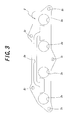
- Fig. 3 is a plane view showing a joining surface of an EGR plate to the cylinder head, the EGR plate is installed on the intake manifold, which is the other one of the two joining surfaces clamping the metal gasket of the embodiment mentioned above therebetween.
- a joining surface 1 for installing an intake manifold, of a cylinder head for an automotive engine shown in Fig. 2 four intake ports 1a as an opening for fluid are provided, and also a gas passage concavity (concave portion) 1b for an EGR system, as an area without pressuring surface, extending in a channel shape from left side to center area on the upper area of the joining surface 1 in the figure.
- lighting concavities (concave portions) 1c for weight reduction as portions having no pressuring surface, which are located on the upper area of the joining surface 1 and areas between adjacent intake ports 1a in the figure, and five bolt installing holes 1d for installing the foregoing EGR plate to the cylinder head on a joining surface 1 for installing the intake manifold.
- extending portion 1e which extends toward another intake port 1a adjacent to the former intake port 1a, is provided.
- a joining surface 2 of the EGR plate installed on the intake manifold shown in Fig. 3 four intake pipe ports 2a as openings for fluid are provided.
- a gas passage concavity 2b for an EGR system as an area without pressuring surface, which is extended left and right side in a channel shape on the upper area of the joining surface 2 with both ends thereof extending downward, and is located between adjacent intake pipe ports 2a which is two pairs each on either side in the figure, and five penetrating holes 2c for fitting bolts for installing the EGR plate to a cylinder head, on the joining surface 2.
- the metal gasket 3 according to the present invention shown in Fig. 1 is made of a blank metal plate of stainless steel, for example, and the metal gasket 3 has four intake through holes 3a connecting the foregoing four intake ports 1a provided on the joining surface 1 of the cylinder head with the foregoing four intake pipe ports 2a provided on the joining surface 2 of the EGR plate, and a continuous full bead 3b having a cross section of a chevron shape as a bead surrounding those intake through holes 3a so as to separate each of the intake through holes 3a, as shown in a state where the metal gasket 3 is held between the joining surfaces 1 and 2 in Fig. 4.
- the metal gasket 3 also has a gas passage through hole 3c connecting the gas passage concavity 1b provided on the joining surface 1 of the cylinder head with the center portion of the foregoing gas passage concavity 2b provided on the joining surface 2 of the EGR plate each other, four gas passage through holes 3d connecting both ends of the foregoing gas passage concavity 2b provided on the joining surface 2 of the EGR plate with extended portions 1e of the foregoing each intake port 1a in the joining surface 1 of the cylinder head, and five penetrating holes 3e for fitting bolts, which are located corresponding to the five bolt installing holes 1d for installing the foregoing EGR plate and the penetrating holes 2c for fitting bolts.
- the foregoing full bead 3b surrounds together the intake through holes 3a corresponding to each intake port 1a and the gas passage through holes 3d corresponding to extended portions 1e of the intake ports 1a to seal the intake through holes 3a and gas passage through holes 3d to the lighting concavities 1c locating between adjacent intake ports 1a, each of two pairs on either sides.
- the full bead 3b surrounds the gas passage through holes 3c as surrounding the gas passage concavity 1b on the joining surface 1.
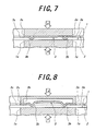
- the metal gasket 3 in the embodiment is shown in Fig. 4 in a state that it is clamped between the foregoing joining surfaces 1 and 2, and as shown in sectional view of Fig.5 taken along a B-B line in Fig. 4, the metal gasket 3 has two balance beads 3f as convex portions, hollow side of which faces to lightning concavities 1c located each between two pairs of adjacent intake ports 1a on left and right side on joining surface 1 of the cylinder head and convex side of which wholly has a shape of approximately a hemisphere.
- the tips of those balance beads 3f abut lower portion of both ends of the gas passage concavity 2b in Fig. 4 on the joining surface 2 of the EGR plate.
- the metal gasket 3 in the embodiment has conventional rubber coating layer (not shown in the drawing) composed of synthetic rubber and the like on both surfaces of the foregoing blank metal plate except whole area of the foregoing balance beads 3f having a shape of approximately a hemisphere, areas composing fluid passage opposite to the gas passage concavity 1b and extended area 1e on the joining surface 1 and areas composing fluid passage opposite to the gas passage concavity 2b on the joining surface 2.
- conventional rubber coating layer (not shown in the drawing) composed of synthetic rubber and the like on both surfaces of the foregoing blank metal plate except whole area of the foregoing balance beads 3f having a shape of approximately a hemisphere, areas composing fluid passage opposite to the gas passage concavity 1b and extended area 1e on the joining surface 1 and areas composing fluid passage opposite to the gas passage concavity 2b on the joining surface 2.
- the metal gasket 3 in this embodiment constituted as mentioned above, after the metal gasket 3 is interposed between the joining surface 1 of the cylinder head and the joining surface 2 of the EGR plate, when two joining surface 1 and 2 are pushed in the closing direction each other as shown with arrow A in Fig. 5 by clamping force of five fitting bolts which are passed through the penetrating holes 2c and 3e for the bolts and screwed on bolt installing holes 1d each. Then, other parts of the full bead 3b except the parts across both ends of the gas passage concavity 2b on the joining surface 2 are clamped between the foregoing joining surfaces 1 and 2 and are pushed strongly to the joining surfaces 1, 2 to generate high surface pressure.
- the gas passage concavity 2b for EGR system is formed on areas opposing partially to the full bead 3b on the joining surface 2 of the EGR plate, which is one of the joining surface 1 of the cylinder head and the joining surface 2 of the EGR plate which are clamping the metal gasket 3 therebetween, at request for further engine exhaust gas cleaning and more improvement in fuel consumption, high sealing properties owing to the high surface pressure can be exerted on whole circumference of the full bead 3b including areas opposite to the gas passage concavity 2b though a single plate-type of metal gasket is employed.
- a highly airtight EGR gas passage which from the gas passage concavity 1b provided on the joining surface 1 of the cylinder head, via the gas passage through hole 3c, passes through the gas passage concavity 2b provided on the joining surface 1 of the cylinder head and from both ends of the gas passage concavity 2b, via the gas passage through holes 3d, reaches extended portion 1e of the foregoing each intake port 1a provided on the joining surface 1 on the cylinder head, is formed.
- balance beads 3f as convex portions are provided on the area where they abut only the joining surface 2 of the EGR plate, that is, at the position of lightning concavity 1c where they do not abut the joining surface 1 of the cylinder head, the balance beads 3f, the tips of which abut the joining surface 2 of the EGR plate, is pushed toward the joining surface 1 of the cylinder head without being restrained by the joining surface 1. Then, parts of the full bead 3b located near the balance beads 3f are pressurized to the joining surface 1 of the cylinder head and higher surface pressure is generated and then higher sealing properties (pressure resistance) can be obtained.
- beads surrounding intake ports 3a and gas passage through holes 3d are the full bead 3b, and also portions abutting only the joining surface 1 of the cylinder head is the tip of the full bead 3b, bead portions abutting only the joining surface 1 of the cylinder head, locating near the balance beads 3f in the metal gasket 3, become the tip of the full bead 3b.
- the tip of the full bead 3 is pressurized strongly to the joining surface 1 of the cylinder head to generate higher surface pressure on areas abutting only the joining surface 1 as one of the joining surfaces, and higher sealing properties (pressure resistance) can be obtained.
- the whole of the balance beads 3f are formed in a hemispherical shape and a conventional rubber coating layer composed of a synthetic rubber and the like is formed on both surfaces of the blank metal plate of the metal gasket 3 except the whole of the balance bead 3f and areas forming the foregoing fluid passages, even if there is a dispersion in flatness within tolerance, uniform pressure can be applied to the area of the full bead 3b abutting only the joining surface 1 of the cylinder head, due to the hemispherical shape of the balance beads 3f abutting the joining surface 2, moreover, the rubber coating layer formed on both surfaces of the blank metal plate of the metal gasket 3 can be deformed elastically corresponding to marks made by tools and the like on the both joining surfaces and then higher sealing properties can be obtained.
- a rubber coating layer is formed on areas except whole of the balance beads 3f and areas forming fluid passages, in the balance beads 3f, wearing of the rubber coating layer by fretting (sliding) on the joining surfaces 1 and 2 generated from repeated temperature variation of an engine can be avoided and at the same time transmission efficiency of pressuring force can be improved.
- the areas forming fluid passages separation of the rubber coating layer by flowing of EGR gas as a fluid can be prevented.
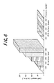
- Table 1 shown below shows test results comparing sealing properties under negative pressure in the metal gasket 3 of the foregoing embodiment having the balance beads 3f and the metal gasket having no balance bead, which is prepared by removing the balance beads 3 from the metal gasket 3, as a comparative example, and Fig. 6 is a graph showing the test results.
- Pressure (mmHg) No balance bead (cc/min) With balance beads (cc/min) -450 29.0 0 -500 55.3 0 -550 101.0 0 -600 150.0 1.0 -650 200.0 2.2
- leak amount at -450 mmHg of the comparative example with no balance bead was 29 cc/min which did not satisfy a predetermined requested performance.
- leak amount of the metal gasket 3 in the foregoing embodiment which has the balance beads 3f was only 2.2 cc/min even at -650 mmHg, which satisfied the predetermined requested ability sufficiently.
- the metal gasket 3 in the foregoing embodiment has extremely high sealing properties.
- the foregoing bead is not limited to a full bead having a chevron shape, but may be a half bead having single slope.
- the foregoing convex portion is not limited to one having almost hemispherical shape and may be one having almost cone shape or a full bead having chevron shape extending in projected line state or a half bead having single slope.
- the metal gasket according to the present invention may be used not only between joining surfaces of an engine but also between other joining surfaces and it is not limited to a single plate-type but may be used as a laminated type.
Landscapes
- Engineering & Computer Science (AREA)
- General Engineering & Computer Science (AREA)
- Mechanical Engineering (AREA)
- Gasket Seals (AREA)
- Cylinder Crankcases Of Internal Combustion Engines (AREA)
Applications Claiming Priority (2)
| Application Number | Priority Date | Filing Date | Title |
|---|---|---|---|
| JP2001184892 | 2001-06-19 | ||
| JP2001184892A JP4028190B2 (ja) | 2001-06-19 | 2001-06-19 | 金属ガスケット |
Publications (3)
| Publication Number | Publication Date |
|---|---|
| EP1271019A2 true EP1271019A2 (fr) | 2003-01-02 |
| EP1271019A3 EP1271019A3 (fr) | 2004-01-21 |
| EP1271019B1 EP1271019B1 (fr) | 2008-08-13 |
Family
ID=19024575
Family Applications (1)
| Application Number | Title | Priority Date | Filing Date |
|---|---|---|---|
| EP02254254A Expired - Lifetime EP1271019B1 (fr) | 2001-06-19 | 2002-06-18 | Joint plat métallique |
Country Status (7)
| Country | Link |
|---|---|
| US (1) | US6957814B2 (fr) |
| EP (1) | EP1271019B1 (fr) |
| JP (1) | JP4028190B2 (fr) |
| CN (1) | CN1267634C (fr) |
| BR (1) | BR0202324B1 (fr) |
| DE (1) | DE60228171D1 (fr) |
| TW (1) | TW530136B (fr) |
Families Citing this family (5)
| Publication number | Priority date | Publication date | Assignee | Title |
|---|---|---|---|---|
| KR101621794B1 (ko) | 2010-01-07 | 2016-05-31 | 삼성전자 주식회사 | 디스플레이장치 |
| JP2012097675A (ja) * | 2010-11-02 | 2012-05-24 | Aisin Seiki Co Ltd | 内燃機関の吸気装置 |
| AT512134B1 (de) * | 2011-11-07 | 2013-08-15 | Bernecker & Rainer Ind Elektronik Gmbh | Hygienegerechtes anzeige- und bediengerät |
| CN107002877B (zh) * | 2014-11-13 | 2018-06-01 | Nok株式会社 | 箱体的密封结构 |
| JP6555901B2 (ja) * | 2015-02-24 | 2019-08-07 | Nok株式会社 | 金属ガスケット |
Family Cites Families (15)
| Publication number | Priority date | Publication date | Assignee | Title |
|---|---|---|---|---|
| FR810728A (fr) * | 1935-12-12 | 1937-03-27 | Le Joint Metalloplastique Fran | Joint métallique |
| GB883267A (en) * | 1959-07-01 | 1961-11-29 | Goetzewerke | Beaded gasket |
| US3930656A (en) * | 1974-02-22 | 1976-01-06 | Parker-Hannifin Corporation | Sealed joint and gasket therefor |
| GB1583322A (en) * | 1978-02-02 | 1981-01-28 | Nicholson T P | Corrugated gaskets |
| US4688809A (en) * | 1985-11-26 | 1987-08-25 | Cummins Engine Company, Inc. | Gasket for internal combustion engine |
| US4796897A (en) * | 1987-08-28 | 1989-01-10 | Fel-Pro Incorporated | Head gasket with beam-functioning fire ring |
| JP2518002Y2 (ja) * | 1989-11-29 | 1996-11-20 | 石川ガスケット 株式会社 | 予備燃焼室付きシリンダヘッド用ガスケット |
| US5221097A (en) * | 1991-12-10 | 1993-06-22 | Ishikawa Gasket Co., Ltd. | Sealing system using metal gasket with projection bead |
| US5700015A (en) * | 1996-09-26 | 1997-12-23 | Dana Corporation | Rubber/metal combustion seal |
| US5695203A (en) * | 1996-09-30 | 1997-12-09 | Ishikawa Gasket Co., Ltd. | Metal gasket with coating layer |
| JP3003026B2 (ja) * | 1996-10-07 | 2000-01-24 | 石川ガスケット株式会社 | 金属板ガスケット |
| US5711537A (en) * | 1996-12-13 | 1998-01-27 | Ishikawa Gasket Co., Ltd. | Metal gasket with a bead surrounding bolt and oil holes |
| DE59907117D1 (de) * | 1998-03-07 | 2003-10-30 | Jung Alfred H | Geprägte dichtungsanordnung für eine flache flanschverbindung |
| JP2001032937A (ja) * | 1999-07-22 | 2001-02-06 | Nippon Gasket Co Ltd | 単層金属ガスケット |
| JP4718660B2 (ja) * | 1999-12-15 | 2011-07-06 | 日本ガスケット株式会社 | 金属製ガスケット |
-
2001
- 2001-06-19 JP JP2001184892A patent/JP4028190B2/ja not_active Expired - Fee Related
-
2002
- 2002-06-17 TW TW091113129A patent/TW530136B/zh not_active IP Right Cessation
- 2002-06-18 US US10/173,096 patent/US6957814B2/en not_active Expired - Lifetime
- 2002-06-18 DE DE60228171T patent/DE60228171D1/de not_active Expired - Lifetime
- 2002-06-18 EP EP02254254A patent/EP1271019B1/fr not_active Expired - Lifetime
- 2002-06-19 BR BRPI0202324-5A patent/BR0202324B1/pt not_active IP Right Cessation
- 2002-06-19 CN CN02124817.6A patent/CN1267634C/zh not_active Expired - Fee Related
Non-Patent Citations (1)
| Title |
|---|
| None |
Also Published As
| Publication number | Publication date |
|---|---|
| CN1267634C (zh) | 2006-08-02 |
| EP1271019B1 (fr) | 2008-08-13 |
| JP4028190B2 (ja) | 2007-12-26 |
| BR0202324B1 (pt) | 2011-05-17 |
| US20030011140A1 (en) | 2003-01-16 |
| TW530136B (en) | 2003-05-01 |
| US6957814B2 (en) | 2005-10-25 |
| DE60228171D1 (de) | 2008-09-25 |
| EP1271019A3 (fr) | 2004-01-21 |
| CN1396379A (zh) | 2003-02-12 |
| JP2003004141A (ja) | 2003-01-08 |
| BR0202324A (pt) | 2003-04-08 |
Similar Documents
| Publication | Publication Date | Title |
|---|---|---|
| US8783692B2 (en) | Multilayer static gasket with bead compression limiter | |
| US5890719A (en) | Combination metal and elastomer cylinder head gasket | |
| EP1398546B1 (fr) | Joint de culasse | |
| CN101821535B (zh) | 金属的气缸盖密封垫 | |
| US5671927A (en) | Gasket assembly with sealing member having main body with integral tabs | |
| US10006403B2 (en) | Cylinder head gasket | |
| CA1133728A (fr) | Plaque d'ecartement stratifiee pour moteurs thermiques, et methode de fabrication connexe | |
| EP2097661A1 (fr) | Joint multicouche | |
| US20180128374A1 (en) | Gasket component with half-stop and method of manfacturing | |
| US6957814B2 (en) | Metal gasket | |
| EP2697541A1 (fr) | Joint d'étanchéité métallique à plusieurs couches ayant un cordon d'étanchéité sur un obturateur, cordon d'étanchéité sur un obturateur | |
| US6619665B2 (en) | Cylinder head gasket with partial resin coatings | |
| US8011674B2 (en) | Metal laminate gasket | |
| US6848690B1 (en) | Seal for head gaskets of internal combustion engines | |
| US7401790B2 (en) | Metal gasket with rigid seal | |
| CN100353095C (zh) | 平板垫片 | |
| WO2009005179A1 (fr) | Joint pour empêcher un pincement | |
| US7311309B2 (en) | Cylinder head gasket | |
| US20060103077A1 (en) | Metal gasket | |
| CN102272494A (zh) | 具有附加密封件的平垫片 | |
| AU2004203205A1 (en) | Gasket having an inner edge with coined angles and method of manufacture | |
| US20070262534A1 (en) | Head gasket for internal combustion engines | |
| US20130106063A1 (en) | Multi-Layer Inserts for Gaskets | |
| JPH0139878Y2 (fr) | ||
| JP2002106717A (ja) | メタルシリンダヘッドガスケット |
Legal Events
| Date | Code | Title | Description |
|---|---|---|---|
| PUAI | Public reference made under article 153(3) epc to a published international application that has entered the european phase |
Free format text: ORIGINAL CODE: 0009012 |
|
| AK | Designated contracting states |
Kind code of ref document: A2 Designated state(s): AT BE CH CY DE DK ES FI FR GB GR IE IT LI LU MC NL PT SE TR |
|
| AX | Request for extension of the european patent |
Free format text: AL;LT;LV;MK;RO;SI |
|
| PUAL | Search report despatched |
Free format text: ORIGINAL CODE: 0009013 |
|
| AK | Designated contracting states |
Kind code of ref document: A3 Designated state(s): AT BE CH CY DE DK ES FI FR GB GR IE IT LI LU MC NL PT SE TR |
|
| AX | Request for extension of the european patent |
Extension state: AL LT LV MK RO SI |
|
| 17P | Request for examination filed |
Effective date: 20040622 |
|
| AKX | Designation fees paid |
Designated state(s): DE GB |
|
| 17Q | First examination report despatched |
Effective date: 20060719 |
|
| GRAP | Despatch of communication of intention to grant a patent |
Free format text: ORIGINAL CODE: EPIDOSNIGR1 |
|
| GRAS | Grant fee paid |
Free format text: ORIGINAL CODE: EPIDOSNIGR3 |
|
| GRAA | (expected) grant |
Free format text: ORIGINAL CODE: 0009210 |
|
| AK | Designated contracting states |
Kind code of ref document: B1 Designated state(s): DE GB |
|
| REG | Reference to a national code |
Ref country code: GB Ref legal event code: FG4D |
|
| REF | Corresponds to: |
Ref document number: 60228171 Country of ref document: DE Date of ref document: 20080925 Kind code of ref document: P |
|
| PLBE | No opposition filed within time limit |
Free format text: ORIGINAL CODE: 0009261 |
|
| STAA | Information on the status of an ep patent application or granted ep patent |
Free format text: STATUS: NO OPPOSITION FILED WITHIN TIME LIMIT |
|
| 26N | No opposition filed |
Effective date: 20090514 |
|
| PGFP | Annual fee paid to national office [announced via postgrant information from national office to epo] |
Ref country code: GB Payment date: 20130516 Year of fee payment: 12 |
|
| GBPC | Gb: european patent ceased through non-payment of renewal fee |
Effective date: 20140618 |
|
| PG25 | Lapsed in a contracting state [announced via postgrant information from national office to epo] |
Ref country code: GB Free format text: LAPSE BECAUSE OF NON-PAYMENT OF DUE FEES Effective date: 20140618 |
|
| PGFP | Annual fee paid to national office [announced via postgrant information from national office to epo] |
Ref country code: DE Payment date: 20150626 Year of fee payment: 14 |
|
| REG | Reference to a national code |
Ref country code: DE Ref legal event code: R119 Ref document number: 60228171 Country of ref document: DE |
|
| PG25 | Lapsed in a contracting state [announced via postgrant information from national office to epo] |
Ref country code: DE Free format text: LAPSE BECAUSE OF NON-PAYMENT OF DUE FEES Effective date: 20170103 |