EP1271027A2 - Dispositif de soupape - Google Patents
Dispositif de soupape Download PDFInfo
- Publication number
- EP1271027A2 EP1271027A2 EP02012814A EP02012814A EP1271027A2 EP 1271027 A2 EP1271027 A2 EP 1271027A2 EP 02012814 A EP02012814 A EP 02012814A EP 02012814 A EP02012814 A EP 02012814A EP 1271027 A2 EP1271027 A2 EP 1271027A2
- Authority
- EP
- European Patent Office
- Prior art keywords
- valve
- block
- media
- valve arrangement
- control
- Prior art date
- Legal status (The legal status is an assumption and is not a legal conclusion. Google has not performed a legal analysis and makes no representation as to the accuracy of the status listed.)
- Granted
Links
- 238000012360 testing method Methods 0.000 claims description 32
- 239000000446 fuel Substances 0.000 description 6
- 238000011990 functional testing Methods 0.000 description 5
- 230000000712 assembly Effects 0.000 description 4
- 238000000429 assembly Methods 0.000 description 4
- 238000009434 installation Methods 0.000 description 3
- 230000008859 change Effects 0.000 description 2
- 230000000052 comparative effect Effects 0.000 description 2
- 230000004044 response Effects 0.000 description 2
- 230000004888 barrier function Effects 0.000 description 1
- 238000006073 displacement reaction Methods 0.000 description 1
- 238000007689 inspection Methods 0.000 description 1
- 230000003993 interaction Effects 0.000 description 1
- 230000007257 malfunction Effects 0.000 description 1
- 230000000306 recurrent effect Effects 0.000 description 1
- 230000009467 reduction Effects 0.000 description 1
- 239000007787 solid Substances 0.000 description 1
- 238000011144 upstream manufacturing Methods 0.000 description 1
- XLYOFNOQVPJJNP-UHFFFAOYSA-N water Substances O XLYOFNOQVPJJNP-UHFFFAOYSA-N 0.000 description 1
Images

Classifications
-
- G—PHYSICS
- G21—NUCLEAR PHYSICS; NUCLEAR ENGINEERING
- G21C—NUCLEAR REACTORS
- G21C9/00—Emergency protection arrangements structurally associated with the reactor, e.g. safety valves provided with pressure equalisation devices
-
- F—MECHANICAL ENGINEERING; LIGHTING; HEATING; WEAPONS; BLASTING
- F15—FLUID-PRESSURE ACTUATORS; HYDRAULICS OR PNEUMATICS IN GENERAL
- F15B—SYSTEMS ACTING BY MEANS OF FLUIDS IN GENERAL; FLUID-PRESSURE ACTUATORS, e.g. SERVOMOTORS; DETAILS OF FLUID-PRESSURE SYSTEMS, NOT OTHERWISE PROVIDED FOR
- F15B13/00—Details of servomotor systems ; Valves for servomotor systems
- F15B13/02—Fluid distribution or supply devices characterised by their adaptation to the control of servomotors
- F15B13/06—Fluid distribution or supply devices characterised by their adaptation to the control of servomotors for use with two or more servomotors
- F15B13/08—Assemblies of units, each for the control of a single servomotor only
- F15B13/0803—Modular units
- F15B13/0807—Manifolds
- F15B13/0817—Multiblock manifolds
-
- F—MECHANICAL ENGINEERING; LIGHTING; HEATING; WEAPONS; BLASTING
- F16—ENGINEERING ELEMENTS AND UNITS; GENERAL MEASURES FOR PRODUCING AND MAINTAINING EFFECTIVE FUNCTIONING OF MACHINES OR INSTALLATIONS; THERMAL INSULATION IN GENERAL
- F16K—VALVES; TAPS; COCKS; ACTUATING-FLOATS; DEVICES FOR VENTING OR AERATING
- F16K17/00—Safety valves; Equalising valves, e.g. pressure relief valves
- F16K17/02—Safety valves; Equalising valves, e.g. pressure relief valves opening on surplus pressure on one side; closing on insufficient pressure on one side
- F16K17/04—Safety valves; Equalising valves, e.g. pressure relief valves opening on surplus pressure on one side; closing on insufficient pressure on one side spring-loaded
- F16K17/10—Safety valves; Equalising valves, e.g. pressure relief valves opening on surplus pressure on one side; closing on insufficient pressure on one side spring-loaded with auxiliary valve for fluid operation of the main valve
-
- Y—GENERAL TAGGING OF NEW TECHNOLOGICAL DEVELOPMENTS; GENERAL TAGGING OF CROSS-SECTIONAL TECHNOLOGIES SPANNING OVER SEVERAL SECTIONS OF THE IPC; TECHNICAL SUBJECTS COVERED BY FORMER USPC CROSS-REFERENCE ART COLLECTIONS [XRACs] AND DIGESTS
- Y02—TECHNOLOGIES OR APPLICATIONS FOR MITIGATION OR ADAPTATION AGAINST CLIMATE CHANGE
- Y02E—REDUCTION OF GREENHOUSE GAS [GHG] EMISSIONS, RELATED TO ENERGY GENERATION, TRANSMISSION OR DISTRIBUTION
- Y02E30/00—Energy generation of nuclear origin
- Y02E30/30—Nuclear fission reactors
Definitions
- the invention relates to a valve arrangement with a shut-off block on which a Safety valve and one with this over a number of led in the shut-off block Media lines communicating control valve are arranged.
- Pressure-carrying components or units of technical systems such as the pressure vessel of a nuclear facility are common by means of safety valves against the occurrence of excess design pressures secured in their interior.
- the pressure vessel a nuclear plant usually has a number of safety valves assigned, which when a predetermined limit pressure in the Release the pressure vessel through a blow-off path. If necessary, via the blow-off path relaxation of the pressure vessel to a pressure level below a limit pressure which is considered admissible.
- safety valves in nuclear plants is due to the prevailing there Comparatively, requirements for operational safety and care compliance strict regulations regarding reliability and reproducibility the closing behavior of the safety valves is also required.
- a such a safety valve can be coupled to a control valve, which in turn can in turn comprise a main control module and a pilot control module.
- a control valve which in turn can in turn comprise a main control module and a pilot control module.
- a valve arrangement is known from DE 196 28 610 C1, which is particularly suitable for is suitable for use in a nuclear power plant.
- This valve assembly includes a safety valve and a pilot and a main control module Control unit, also known as a control valve.
- Both the safety valve and the control valve of the known valve arrangement are according to the so-called Relief principle designed, the closed state of the safety valve and also the control valve with a suitable application high pressure is maintained from a pressurized system. If at this valve arrangement the contact pressure of the control valve is exceeded, so a blow-off system is opened via a pressure-displacement converter Control valve, which leads to relief of a control chamber of the control valve.
- Such a valve arrangement can comprise a so-called shut-off block, on which the safety valve and the control valve are mounted.
- this block are usually the media lines through which the safety valve communicates with the control valve.
- These include media lines the relief lines mentioned, via which the control rooms of the control valve and the safety valve are relieved of pressure, as well as impulse lines for forwarding the pressure from the pressure vessel to be protected and / or Filling lines through which the control rooms after actuation of the respective Valve can be pressurized again.
- valve arrangements are usually safety-relevant Components in a nuclear facility. Because of this and because of the Strict safety precautions to be observed when used in a nuclear facility are such valve arrangements when used in a nuclear plant usually subjected to a variety of functional tests. This is usually after the installation of such a valve arrangement Initially, a so-called adjustment test is provided, in which the basic settings the respective valve arrangement such as the response pressure, spring forces or travel with regard to the existing requirements or in With regard to the special requirements of each system. In addition, functional tests of all individual components can be carried out the valve arrangement as well as recurrent tests of the valve arrangement in the With regard to individual situations.
- the setting test is the Main inspection of the respective valve arrangement, which was carried out during their installation becomes.
- valve assemblies used to secure the pressure vessel tend to form a leak in about this period is common together with the replacement of fuel elements, which is already a temporary one
- a shutdown of the respective nuclear power plant requires a parallel one Standard replacement of valve arrangements provided.
- the new one Installed valve assemblies are usually installed before or during commissioning the functional tests mentioned, in particular the adjustment test, subjected.
- the invention is therefore based on the object, a valve arrangement of the above Specify the type mentioned, in which the handling or operating effort kept particularly low for carrying out the functional tests mentioned is.
- shut-off block one Main block and an adapter block releasably connected to this the a number of determining the media-side interconnection of the media lines Control channels has.
- the invention is based on the consideration that the effort involved in testing the valve arrangement can be kept particularly low by this in installed condition and with only minor manipulations of your operating configuration can be switched to their test configuration and vice versa.
- the operational configuration and the test configuration usually differ only in the type of connection of the control valve and the safety valve media lines connecting each other and their outside world.
- a suitable switchover between operational configuration and test configuration can therefore be achieved by connecting the circuit in a particularly simple manner the media lines are kept changeable.
- the shut-off block is in a main block and divided into an adapter block, the main block being both to attach the control valve and safety valve serves as the essential Parts of the media lines leads. Control channels are in the adapter block led such that by a suitable combination with those in the main block provided media lines, the desired interconnection is created.
- the media lines lead to making a large number of circuit variants available in an advantageous embodiment in the main block according to a predefinable Standard determined positions in the interface to the adapter block. Consequently can be a variety of adapter blocks, which due to appropriate guidance of the control channels integrated in it each have a different interconnection of the media lines specify to be combined with the main block without further effort, since these are only subject to the constraint that the standard given positions in their interface to the main block the corresponding Control channels must end.
- the main block is alternatively advantageously with an operating configuration the adapter block corresponding to the media lines or with a one Test configuration of the media lines can be combined with the corresponding adapter block.
- the safety valve of the valve arrangement is advantageously based on the relief principle or carried out according to the load principle.
- the advantages achieved by the invention are in particular that the division of the between the safety valve and the control valve Barrier blocks in a main block and an adapter block on special simple switching of the valve arrangement between different Switching states of the media lines is enabled.
- the Main block on which the safety valve and the control valve are mounted the media lines are predefined in their essential course his.
- the arrangement of the safety valve, control valve and the intermediary The main block can also be used when switching the media-side interconnection remain permanently installed.
- Switching between different switching states of the valve arrangement can be done by simply replacing the adapter block, the Media-side interconnection of the media lines through the customized in control block guided adapter block takes place.
- the adapter block provides thus in the manner of a "hard-wired component" sure that by the exchange switching of only one component also between comparatively complex ones Switching states can be done easily, especially in comparison complex media-side circuits reliably avoid switching errors are, especially since an individual line installation is not required. This is a situation-specific switch between test configuration and operating configuration of the valve arrangement at any time with little effort possible. Thus, the effort involved in testing such a valve arrangement kept particularly low, which in particular further use of such a valve arrangement particularly over several operating cycles is relieved.
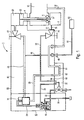
- the valve arrangement 1 according to FIG. 1 is for securing the pressure of a pressure vessel 2 provided.
- the pressure vessel 2 can in particular the pressure vessel a nuclear plant or a nuclear power plant.
- the valve assembly 1 includes a safety valve to secure the pressure vessel 2 4.
- the safety valve 4 comprises a valve cone 6, which in the normal state Blow-off opening 8 of the pressure vessel closes tightly. However, if the pressure in the Pressure vessel 2 exceeds a predefinable setpoint, the safety valve opens 4, the valve cone 6 opening the blow-off opening 8. This will make the interior of the pressure vessel 2 connected to a blow-off line 10, via the When the safety valve is open 4 gas, water and / or steam from the interior of the pressure vessel 2 to a downstream collecting device or in the environment can be drained. If the pressure in the pressure tank 2 safety valve 4, on the other hand, closes again, so that the interior of the pressure vessel 2 again on the pressure side is decoupled from the blow-off line 10.
- the safety valve 4 is a control valve in the manner of a control device 12 assigned.
- the control valve 12 is in turn designed in two stages and includes a main control module 14 and an upstream pilot module 16th
- the valve arrangement 1 is designed according to the relief principle. To do this includes the safety valve 4 has a control chamber 20 which, in the normal operating state is subjected to a working pressure. Due to this working pressure, a in the control chamber 20 guided piston 22 of the valve cone 6 securely in its blow-off opening 8 of the pressure vessel 2 closing valve seat held. in the Relief occurs, a relief or a pressure reduction in the control room 20, see above that the pressure prevailing in the pressure vessel 2 pushes the valve cone 6 out of its seat moves and thus releases the relief opening.
- the need-based relief of the control room 20 for targeted control of the safety valve 4 takes place via a first media line 24, via which the Control room 20 is connected to the main control module 14. Opens in response the main control module 14 connects the first media line 24 to a second media line 26, which is connected on the outlet side to the blow-off channel 10 is. Provide the first media line 24 and the second media line 26 thus in its entirety a relief line that can be released by the main control module 14 for the control room 20 of the safety valve 4.
- the main control module 14 is itself also media-controlled and in addition connected to the pilot module 16 via a third media line 28.
- pilot module 16 provides a connection to the third media line 28 with a guided media line 30 free, the output side in not shown Way is also connected to a blow-off channel.
- the third media line 28 and the fourth media line 30 that can be connected to this position in its entirety also represents a relief line through which the main control module 14 can be relieved on the pressure side. As a result of such Pressure relief of the main control module 14 switches the first media line 24 to relieve pressure in the control chamber 20 of the safety valve 4.
- the pilot control module 16 To trigger a relief of the main control module 14 by producing one Connection between the third media line 28 and the fourth media line 30 is the pilot control module 16 via the pressure prevailing in the pressure vessel 2 driven.
- the pilot control module 16 is designed as a pulse line fifth media line 32 connected to the interior of the pressure vessel 2.
- One of the fifth media line 32 branches off as a fill line for the pilot control module 16 configured sixth media line 34.
- the safety valve 4 and the control valve 12 communicating with it via the media lines 24, 26, 28, 30, 32, 34 are designed in the manner described in DE 196 28 610 C1.
- the media lines 24, 26, 28, 30, 32, 34 are in particular designed as suitable bores or channels.
- the safety valve 4 and the control valve 12 assigned to it are arranged on a common shut-off block 40, on which they are mechanically fixed on the one hand and in which on the other hand the media lines 24, 26, 28, 30, 32, 34 are guided.
- Aids and fittings such as, for example, an externally actuated shut-off valve 42 for the first media line 24 or an externally actuated shut-off valve 44 for the fifth media line 32 are also integrated in the shut-off block 40.
- a branch line 46 branching from the first media line 24 is also guided through the shut-off block 40 and is connected to a pressure sensor 52 via a flange 48 and a line 50. Via the pressure sensor 52, the pressure currently present in the control chamber 20 of the safety valve 4 can also be detected during the operation of the valve arrangement 1.
- the fifth media line 32 emerging from the shut-off block 40 in the area of the shut-off valve 44 is connected to the pressure vessel 2 via a flange 54 connected to the shut-off block 40 and a removal line 56 connected to it.
- the valve arrangement 1 is, in particular due to the design of the safety valve 4 and the control valve 12, also for use over a comparatively suitable for a long period of time in a core Kratttechnik facility.
- the valve arrangement 1 is used, it is provided in particular continue to be used even after a number of fuel element cycles.
- Around but always ensuring the greatest possible plant safety is during a regular fuel element change is not a complete one Replacement of the valve arrangement 1, but at least a complete function check the valve assembly 1 provided.
- the valve assembly 1 is therefore designed to perform such a function check when installed to enable with comparatively little effort.
- the shut-off block 40 in which the safety valve 4 and the control valve 12 media lines 24 connecting one another and with the outside world, 26, 28, 30, 32, 34 are performed in two parts and includes one as the actual Carrier block provided main block 60 and a detachable with this connected adapter block 62.
- the main block 60 is comparatively solid executed and also serves as a support block for the control valve 12.
- Der Adapter block 62 is comparative to main block 60 small size and includes a number of media side Interconnection of the media lines 24, 26, 28, 30, 32, 34 determining control channels 64th
- the adapter block 62 is an operating adapter or operating flange, the control channels guided in it 64 for setting a medium-side operating configuration for the valve arrangement 1 are designed. This is in particular the second medium line 26 held continuously over one of the control channels 64. Likewise, one of the Control channels 64 held the fifth media line 32 continuously.
- the media lines 24, 26, 28, 30, 32, 34 open into the main block 60 at interfaces 66 determined according to a predefinable standard to adapter block 62.
- test configuration in a shown in the embodiment of FIG. 2 The test configuration is carried out in that for setting the operating configuration designed adapter block 62 is replaced by one for setting the Test configuration designed further adapter block 70.
- This thus serves as Test adapter or test flange.
- For the functional test of the valve arrangement 1 is namely provided a targeted in the depressurized state of the pressure vessel 2 Actuation of individual active components of the valve arrangement 1, for example the pilot control module 16 or the main control module 14 with test pressures under test conditions.
- the additional adapter block 70 for one on these test conditions coordinated media connection of media lines 24, 26, 28, 30, 32, 34 designed.
- the further adapter block 70 has control channels 72, which are connected to the now desired media-side interconnection are adapted.
- the second media line 26 and the fifth media line 32 are not continuous led, but made accessible with two half parts separately.
- the control channels 72 which are suitably connected to the second media line 26 and are connected to the fifth media line 32, essentially passed straight through the additional adapter block 70.
- the control channels 72 ends on the output side in test flanges 74, to which one for carrying out the Suitable test device can be connected.
- valve arrangement 1 there is a switchover between the operating configuration and test configuration in a particularly simple manner simply by an exchange allows the adapter blocks 62, 70 against each other.
- the switchover can thus be carried out with particularly little operating effort, in particular also connection errors during the switchover - for example when comparative complex, media-based interconnection - safely avoided.
- the adjustment test of the control valve 12 can be carried out.
- the safety valve 4 is also designed according to the relief principle.
- the concept of the valve arrangement 1 is also suitable for an after Load principle executed safety valve, in which case the the additional adapter block 70 designed as a test flange also performs the motion test of the safety valve can be carried out in a particularly simple manner.
Landscapes
- Engineering & Computer Science (AREA)
- General Engineering & Computer Science (AREA)
- Physics & Mathematics (AREA)
- Mechanical Engineering (AREA)
- High Energy & Nuclear Physics (AREA)
- Plasma & Fusion (AREA)
- Fluid Mechanics (AREA)
- Safety Valves (AREA)
- Valve Housings (AREA)
- Feeding And Controlling Fuel (AREA)
- Pipeline Systems (AREA)
- Magnetically Actuated Valves (AREA)
- Lift Valve (AREA)
Applications Claiming Priority (4)
| Application Number | Priority Date | Filing Date | Title |
|---|---|---|---|
| DE10129396 | 2001-06-20 | ||
| DE10129396 | 2001-06-20 | ||
| DE10161121A DE10161121B4 (de) | 2001-06-20 | 2001-12-12 | Ventilanordnung |
| DE10161121 | 2001-12-12 |
Publications (3)
| Publication Number | Publication Date |
|---|---|
| EP1271027A2 true EP1271027A2 (fr) | 2003-01-02 |
| EP1271027A3 EP1271027A3 (fr) | 2006-02-15 |
| EP1271027B1 EP1271027B1 (fr) | 2008-04-23 |
Family
ID=26009546
Family Applications (1)
| Application Number | Title | Priority Date | Filing Date |
|---|---|---|---|
| EP02012814A Expired - Lifetime EP1271027B1 (fr) | 2001-06-20 | 2002-06-10 | Dispositif de soupape |
Country Status (3)
| Country | Link |
|---|---|
| EP (1) | EP1271027B1 (fr) |
| AT (1) | ATE393342T1 (fr) |
| DE (1) | DE50212131D1 (fr) |
Cited By (1)
| Publication number | Priority date | Publication date | Assignee | Title |
|---|---|---|---|---|
| EP1914460A3 (fr) * | 2006-10-18 | 2012-06-13 | AREVA NP GmbH | Procédé et dispositif destinés à la vérification de la fonctionnalité d'un système de ventilation |
Citations (1)
| Publication number | Priority date | Publication date | Assignee | Title |
|---|---|---|---|---|
| DE19628610C1 (de) | 1996-07-16 | 1998-01-02 | Siemens Ag | Steuereinrichtung |
Family Cites Families (3)
| Publication number | Priority date | Publication date | Assignee | Title |
|---|---|---|---|---|
| US4722361A (en) * | 1983-09-22 | 1988-02-02 | Vapor Corporation | Modulating pressure operated pilot relief valve |
| US5842501A (en) * | 1996-08-23 | 1998-12-01 | Flow Safe, Inc. | Pilot operated safety relief valve |
| US6186600B1 (en) * | 1999-06-10 | 2001-02-13 | Westinghouse Air Brake Company | Automatic test connector adapter plate for AB pipe bracket |
-
2002
- 2002-06-10 AT AT02012814T patent/ATE393342T1/de not_active IP Right Cessation
- 2002-06-10 EP EP02012814A patent/EP1271027B1/fr not_active Expired - Lifetime
- 2002-06-10 DE DE50212131T patent/DE50212131D1/de not_active Expired - Lifetime
Patent Citations (1)
| Publication number | Priority date | Publication date | Assignee | Title |
|---|---|---|---|---|
| DE19628610C1 (de) | 1996-07-16 | 1998-01-02 | Siemens Ag | Steuereinrichtung |
Cited By (1)
| Publication number | Priority date | Publication date | Assignee | Title |
|---|---|---|---|---|
| EP1914460A3 (fr) * | 2006-10-18 | 2012-06-13 | AREVA NP GmbH | Procédé et dispositif destinés à la vérification de la fonctionnalité d'un système de ventilation |
Also Published As
| Publication number | Publication date |
|---|---|
| EP1271027B1 (fr) | 2008-04-23 |
| EP1271027A3 (fr) | 2006-02-15 |
| ATE393342T1 (de) | 2008-05-15 |
| DE50212131D1 (de) | 2008-06-05 |
Similar Documents
| Publication | Publication Date | Title |
|---|---|---|
| EP3479008B1 (fr) | Soupape de réservoir | |
| EP1630425B1 (fr) | Circuit de sécurité pour un actionneur à actionnement par fluide et méthode pour son utilisation | |
| EP2172656B1 (fr) | Unité de déclenchement hydraulique pour une unité de vanne dans une machine motrice, en particulier pour une vanne de fermeture rapide de turbine | |
| CH666132A5 (de) | Einrichtung zur ueberwachung von physikalischen groessen an anlagen. | |
| DE102013105910A1 (de) | Elektronisch steuerbares und prüfbares Turbinenschnellschlusssystem und Verfahren mit redundanten Ablassverteilern | |
| EP0054602B1 (fr) | Soupape d'arrêt contrôlée par son propre fluide | |
| EP2675672B1 (fr) | Soupape de protection multicircuits pour dispositif d'alimentation en air comprimé d'un véhicule et procédé de fonctionnement d'une soupape de protection multicircuit | |
| EP3727610A1 (fr) | Appareil de commande pneumatique pour des installations d'extinction d'incendie multizone, ainsi qu'installation d'extinction d'incendie multizone le comprenant | |
| DE2759263A1 (de) | Ueberwachungssystem fuer hydraulisch betriebene armaturen | |
| DE202011109158U1 (de) | Elektrohydraulische Sicherheitssteuerung | |
| DE102011082599B4 (de) | Ventilanordnung, Verwendung, Turbine und Kraftwerk | |
| EP1271027A2 (fr) | Dispositif de soupape | |
| DE10161121B4 (de) | Ventilanordnung | |
| DE102016115360A1 (de) | Überströmventil zum zumindest teilweisen Verschließen und Öffnen eines Fluidleitungssystems | |
| DE102005040039B4 (de) | Ventilanordnung zur Ansteuerung eines Bauelements | |
| DE19532928C2 (de) | Sicherheitsventilanordnung zum Einsatz an Druckhaltersystemen von Kraftwerken | |
| EP0717201B1 (fr) | Système de protection dans une installation sous pression | |
| DE3040367A1 (de) | Sicherheitsschaltung | |
| CH660510A5 (de) | Auf ihre funktionssicherheit hin pruefbare schutzeinrichtung fuer dampfturbinenanlagen. | |
| WO2005008111A1 (fr) | Dispositif de decompression destine a des systemes de maintien de pression de centrales electriques | |
| DE102015210274A1 (de) | Mehrwegeventil, insbesondere ein 6/2-Wegeventil und Mehrwegeventilanordnung | |
| DE102012105350A1 (de) | Ventil für eine Getränkeabfüllanlage, bevorzugt Ventil für ein Füllorgan einer Getränkeabfüllanlage | |
| DE202005021076U1 (de) | Ventilanordnung zur Ansteuerung eines Bauelements | |
| EP0301202B1 (fr) | Dispositif de soupape pour fluide sous pression | |
| DE2430765C2 (fr) |
Legal Events
| Date | Code | Title | Description |
|---|---|---|---|
| PUAI | Public reference made under article 153(3) epc to a published international application that has entered the european phase |
Free format text: ORIGINAL CODE: 0009012 |
|
| AK | Designated contracting states |
Kind code of ref document: A2 Designated state(s): AT BE CH CY DE DK ES FI FR GB GR IE IT LI LU MC NL PT SE TR |
|
| AX | Request for extension of the european patent |
Free format text: AL;LT;LV;MK;RO;SI |
|
| PUAL | Search report despatched |
Free format text: ORIGINAL CODE: 0009013 |
|
| AK | Designated contracting states |
Kind code of ref document: A3 Designated state(s): AT BE CH CY DE DK ES FI FR GB GR IE IT LI LU MC NL PT SE TR |
|
| AX | Request for extension of the european patent |
Extension state: AL LT LV MK RO SI |
|
| RIC1 | Information provided on ipc code assigned before grant |
Ipc: F16K 17/10 20060101AFI20021004BHEP Ipc: F15B 13/00 20060101ALI20051223BHEP |
|
| 17P | Request for examination filed |
Effective date: 20060804 |
|
| AKX | Designation fees paid |
Designated state(s): AT BE CH CY DE DK ES FI FR GB GR IE IT LI LU MC NL PT SE TR |
|
| GRAP | Despatch of communication of intention to grant a patent |
Free format text: ORIGINAL CODE: EPIDOSNIGR1 |
|
| RAP1 | Party data changed (applicant data changed or rights of an application transferred) |
Owner name: AREVA NP GMBH |
|
| GRAS | Grant fee paid |
Free format text: ORIGINAL CODE: EPIDOSNIGR3 |
|
| GRAA | (expected) grant |
Free format text: ORIGINAL CODE: 0009210 |
|
| AK | Designated contracting states |
Kind code of ref document: B1 Designated state(s): AT BE CH CY DE DK ES FI FR GB GR IE IT LI LU MC NL PT SE TR |
|
| REG | Reference to a national code |
Ref country code: GB Ref legal event code: FG4D Free format text: NOT ENGLISH |
|
| REG | Reference to a national code |
Ref country code: CH Ref legal event code: EP |
|
| REF | Corresponds to: |
Ref document number: 50212131 Country of ref document: DE Date of ref document: 20080605 Kind code of ref document: P |
|
| REG | Reference to a national code |
Ref country code: IE Ref legal event code: FG4D Free format text: LANGUAGE OF EP DOCUMENT: GERMAN |
|
| REG | Reference to a national code |
Ref country code: CH Ref legal event code: NV |
|
| REG | Reference to a national code |
Ref country code: SE Ref legal event code: TRGR |
|
| PG25 | Lapsed in a contracting state [announced via postgrant information from national office to epo] |
Ref country code: ES Free format text: LAPSE BECAUSE OF FAILURE TO SUBMIT A TRANSLATION OF THE DESCRIPTION OR TO PAY THE FEE WITHIN THE PRESCRIBED TIME-LIMIT Effective date: 20080803 Ref country code: PT Free format text: LAPSE BECAUSE OF FAILURE TO SUBMIT A TRANSLATION OF THE DESCRIPTION OR TO PAY THE FEE WITHIN THE PRESCRIBED TIME-LIMIT Effective date: 20080923 |
|
| REG | Reference to a national code |
Ref country code: IE Ref legal event code: FD4D |
|
| BERE | Be: lapsed |
Owner name: AREVA NP G.M.B.H. Effective date: 20080630 |
|
| PG25 | Lapsed in a contracting state [announced via postgrant information from national office to epo] |
Ref country code: IE Free format text: LAPSE BECAUSE OF FAILURE TO SUBMIT A TRANSLATION OF THE DESCRIPTION OR TO PAY THE FEE WITHIN THE PRESCRIBED TIME-LIMIT Effective date: 20080423 Ref country code: MC Free format text: LAPSE BECAUSE OF NON-PAYMENT OF DUE FEES Effective date: 20080630 Ref country code: DK Free format text: LAPSE BECAUSE OF FAILURE TO SUBMIT A TRANSLATION OF THE DESCRIPTION OR TO PAY THE FEE WITHIN THE PRESCRIBED TIME-LIMIT Effective date: 20080423 |
|
| ET | Fr: translation filed | ||
| PLBE | No opposition filed within time limit |
Free format text: ORIGINAL CODE: 0009261 |
|
| STAA | Information on the status of an ep patent application or granted ep patent |
Free format text: STATUS: NO OPPOSITION FILED WITHIN TIME LIMIT |
|
| PG25 | Lapsed in a contracting state [announced via postgrant information from national office to epo] |
Ref country code: BE Free format text: LAPSE BECAUSE OF NON-PAYMENT OF DUE FEES Effective date: 20080630 |
|
| 26N | No opposition filed |
Effective date: 20090126 |
|
| PG25 | Lapsed in a contracting state [announced via postgrant information from national office to epo] |
Ref country code: IT Free format text: LAPSE BECAUSE OF FAILURE TO SUBMIT A TRANSLATION OF THE DESCRIPTION OR TO PAY THE FEE WITHIN THE PRESCRIBED TIME-LIMIT Effective date: 20080423 Ref country code: AT Free format text: LAPSE BECAUSE OF NON-PAYMENT OF DUE FEES Effective date: 20080610 |
|
| PG25 | Lapsed in a contracting state [announced via postgrant information from national office to epo] |
Ref country code: LU Free format text: LAPSE BECAUSE OF NON-PAYMENT OF DUE FEES Effective date: 20080610 Ref country code: CY Free format text: LAPSE BECAUSE OF FAILURE TO SUBMIT A TRANSLATION OF THE DESCRIPTION OR TO PAY THE FEE WITHIN THE PRESCRIBED TIME-LIMIT Effective date: 20080423 |
|
| PG25 | Lapsed in a contracting state [announced via postgrant information from national office to epo] |
Ref country code: TR Free format text: LAPSE BECAUSE OF FAILURE TO SUBMIT A TRANSLATION OF THE DESCRIPTION OR TO PAY THE FEE WITHIN THE PRESCRIBED TIME-LIMIT Effective date: 20080423 |
|
| PG25 | Lapsed in a contracting state [announced via postgrant information from national office to epo] |
Ref country code: GR Free format text: LAPSE BECAUSE OF FAILURE TO SUBMIT A TRANSLATION OF THE DESCRIPTION OR TO PAY THE FEE WITHIN THE PRESCRIBED TIME-LIMIT Effective date: 20080724 |
|
| REG | Reference to a national code |
Ref country code: DE Ref legal event code: R082 Ref document number: 50212131 Country of ref document: DE Representative=s name: TERGAU & WALKENHORST PATENTANWAELTE - RECHTSAN, DE |
|
| REG | Reference to a national code |
Ref country code: DE Ref legal event code: R082 Ref document number: 50212131 Country of ref document: DE Representative=s name: TERGAU & WALKENHORST PATENTANWAELTE PARTGMBB, DE Effective date: 20130523 Ref country code: DE Ref legal event code: R082 Ref document number: 50212131 Country of ref document: DE Representative=s name: TERGAU & WALKENHORST PATENTANWAELTE - RECHTSAN, DE Effective date: 20130523 Ref country code: DE Ref legal event code: R081 Ref document number: 50212131 Country of ref document: DE Owner name: AREVA GMBH, DE Free format text: FORMER OWNER: AREVA NP GMBH, 91052 ERLANGEN, DE Effective date: 20130523 |
|
| PGFP | Annual fee paid to national office [announced via postgrant information from national office to epo] |
Ref country code: GB Payment date: 20140620 Year of fee payment: 13 |
|
| PGFP | Annual fee paid to national office [announced via postgrant information from national office to epo] |
Ref country code: CH Payment date: 20140620 Year of fee payment: 13 Ref country code: SE Payment date: 20140623 Year of fee payment: 13 Ref country code: NL Payment date: 20140618 Year of fee payment: 13 Ref country code: FI Payment date: 20140618 Year of fee payment: 13 |
|
| PG25 | Lapsed in a contracting state [announced via postgrant information from national office to epo] |
Ref country code: FI Free format text: LAPSE BECAUSE OF NON-PAYMENT OF DUE FEES Effective date: 20150610 |
|
| REG | Reference to a national code |
Ref country code: CH Ref legal event code: PL |
|
| REG | Reference to a national code |
Ref country code: SE Ref legal event code: EUG |
|
| GBPC | Gb: european patent ceased through non-payment of renewal fee |
Effective date: 20150610 |
|
| PG25 | Lapsed in a contracting state [announced via postgrant information from national office to epo] |
Ref country code: SE Free format text: LAPSE BECAUSE OF NON-PAYMENT OF DUE FEES Effective date: 20150611 |
|
| REG | Reference to a national code |
Ref country code: NL Ref legal event code: MM Effective date: 20150701 |
|
| PG25 | Lapsed in a contracting state [announced via postgrant information from national office to epo] |
Ref country code: LI Free format text: LAPSE BECAUSE OF NON-PAYMENT OF DUE FEES Effective date: 20150630 Ref country code: NL Free format text: LAPSE BECAUSE OF NON-PAYMENT OF DUE FEES Effective date: 20150701 Ref country code: CH Free format text: LAPSE BECAUSE OF NON-PAYMENT OF DUE FEES Effective date: 20150630 Ref country code: GB Free format text: LAPSE BECAUSE OF NON-PAYMENT OF DUE FEES Effective date: 20150610 |
|
| REG | Reference to a national code |
Ref country code: FR Ref legal event code: PLFP Year of fee payment: 15 |
|
| PGFP | Annual fee paid to national office [announced via postgrant information from national office to epo] |
Ref country code: DE Payment date: 20160627 Year of fee payment: 15 |
|
| REG | Reference to a national code |
Ref country code: FR Ref legal event code: PLFP Year of fee payment: 16 |
|
| PGFP | Annual fee paid to national office [announced via postgrant information from national office to epo] |
Ref country code: FR Payment date: 20170621 Year of fee payment: 16 |
|
| REG | Reference to a national code |
Ref country code: DE Ref legal event code: R119 Ref document number: 50212131 Country of ref document: DE |
|
| PG25 | Lapsed in a contracting state [announced via postgrant information from national office to epo] |
Ref country code: DE Free format text: LAPSE BECAUSE OF NON-PAYMENT OF DUE FEES Effective date: 20180103 |
|
| PG25 | Lapsed in a contracting state [announced via postgrant information from national office to epo] |
Ref country code: FR Free format text: LAPSE BECAUSE OF NON-PAYMENT OF DUE FEES Effective date: 20180630 |