EP1271187A2 - Reflektor und reflektierende Flüssigkristallanzeige - Google Patents
Reflektor und reflektierende Flüssigkristallanzeige Download PDFInfo
- Publication number
- EP1271187A2 EP1271187A2 EP02252646A EP02252646A EP1271187A2 EP 1271187 A2 EP1271187 A2 EP 1271187A2 EP 02252646 A EP02252646 A EP 02252646A EP 02252646 A EP02252646 A EP 02252646A EP 1271187 A2 EP1271187 A2 EP 1271187A2
- Authority
- EP
- European Patent Office
- Prior art keywords
- curve
- reflector
- concave portion
- liquid crystal
- angle
- Prior art date
- Legal status (The legal status is an assumption and is not a legal conclusion. Google has not performed a legal analysis and makes no representation as to the accuracy of the status listed.)
- Ceased
Links
Images


Classifications
-
- G—PHYSICS
- G02—OPTICS
- G02F—OPTICAL DEVICES OR ARRANGEMENTS FOR THE CONTROL OF LIGHT BY MODIFICATION OF THE OPTICAL PROPERTIES OF THE MEDIA OF THE ELEMENTS INVOLVED THEREIN; NON-LINEAR OPTICS; FREQUENCY-CHANGING OF LIGHT; OPTICAL LOGIC ELEMENTS; OPTICAL ANALOGUE/DIGITAL CONVERTERS
- G02F1/00—Devices or arrangements for the control of the intensity, colour, phase, polarisation or direction of light arriving from an independent light source, e.g. switching, gating or modulating; Non-linear optics
- G02F1/01—Devices or arrangements for the control of the intensity, colour, phase, polarisation or direction of light arriving from an independent light source, e.g. switching, gating or modulating; Non-linear optics for the control of the intensity, phase, polarisation or colour
- G02F1/13—Devices or arrangements for the control of the intensity, colour, phase, polarisation or direction of light arriving from an independent light source, e.g. switching, gating or modulating; Non-linear optics for the control of the intensity, phase, polarisation or colour based on liquid crystals, e.g. single liquid crystal display cells
- G02F1/133—Constructional arrangements; Operation of liquid crystal cells; Circuit arrangements
- G02F1/1333—Constructional arrangements; Manufacturing methods
- G02F1/1335—Structural association of cells with optical devices, e.g. polarisers or reflectors
-
- G—PHYSICS
- G02—OPTICS
- G02B—OPTICAL ELEMENTS, SYSTEMS OR APPARATUS
- G02B5/00—Optical elements other than lenses
- G02B5/08—Mirrors
-
- G—PHYSICS
- G02—OPTICS
- G02F—OPTICAL DEVICES OR ARRANGEMENTS FOR THE CONTROL OF LIGHT BY MODIFICATION OF THE OPTICAL PROPERTIES OF THE MEDIA OF THE ELEMENTS INVOLVED THEREIN; NON-LINEAR OPTICS; FREQUENCY-CHANGING OF LIGHT; OPTICAL LOGIC ELEMENTS; OPTICAL ANALOGUE/DIGITAL CONVERTERS
- G02F1/00—Devices or arrangements for the control of the intensity, colour, phase, polarisation or direction of light arriving from an independent light source, e.g. switching, gating or modulating; Non-linear optics
- G02F1/01—Devices or arrangements for the control of the intensity, colour, phase, polarisation or direction of light arriving from an independent light source, e.g. switching, gating or modulating; Non-linear optics for the control of the intensity, phase, polarisation or colour
- G02F1/13—Devices or arrangements for the control of the intensity, colour, phase, polarisation or direction of light arriving from an independent light source, e.g. switching, gating or modulating; Non-linear optics for the control of the intensity, phase, polarisation or colour based on liquid crystals, e.g. single liquid crystal display cells
- G02F1/133—Constructional arrangements; Operation of liquid crystal cells; Circuit arrangements
- G02F1/1333—Constructional arrangements; Manufacturing methods
- G02F1/1335—Structural association of cells with optical devices, e.g. polarisers or reflectors
- G02F1/133553—Reflecting elements
Definitions
- the present invention relates to reflectors and reflective liquid crystal displays, and more specifically relates to a reflector having reflection characteristics such that it appears brighter when reflection light is observed at a specific viewing angle than when it is observed at other viewing angles, and to a reflective liquid crystal display using the reflector.
- Liquid crystal displays can be generally classified into two types: transmissive liquid crystal displays and reflective liquid crystal displays.
- reflective liquid crystal displays external light is used for illumination and a front light is used for ensuring visibility.
- Reflective liquid crystal displays are commonly used as display units for electronic devices such as mobile computers, calculators, digital watches, communication equipment, game machines, measuring devices, electronic display boards, etc.
- FIG. 8 An example of a reflective liquid crystal display is shown in Fig. 8. With reference to Fig. 8, a display-side substrate 20 and a reflector-side substrate 10 oppose each other with a liquid crystal layer 30 therebetween.
- the display-side substrate 20 is transmissive and the reflector-side substrate 10 is reflective.
- the external surface of the display-side substrate 20 serves as a display surface, and the reflector-side substrate 10 is provided with a reflective layer 12.
- external light incident on the display surface passes through the display-side substrate 20 and the liquid crystal layer 30, is reflected by the reflective layer 12 in the reflector-side substrate 10, passes through the liquid crystal layer 30 again, and is emitted from the display surface, thereby making an image visible.
- the reflector-side substrate 10 is formed by laminating a glass substrate 11, the reflective layer 12, an intervening layer 13, a color-filter layer 14, a planarizing layer 15, a transparent electrode layer 16 formed of an Indium Tin Oxide (ITO) film, a Nesa film, etc., and an alignment layer 17, in that order from the bottom.
- ITO Indium Tin Oxide
- the display-side substrate 20 which opposes the reflector-side substrate 10 across the liquid crystal layer 30, is formed by laminating an alignment layer 21, an insulating layer 22, a transparent electrode layer 23 formed of an ITO film, a Nesa film, etc., a glass substrate 24, and a light-modulating layer 25 (a polarizing plate, a retardation plate, etc.) in that order from the liquid crystal layer 30.
- the color-filter layer 14 in the reflector-side substrate 10 includes red (R), green (G), and blue (B) color films which are sequentially arranged in parallel to each other in a striped pattern
- the transparent electrode layer 16 includes transparent electrodes disposed in parallel to each other in a striped pattern at positions corresponding to the color films.
- the transparent electrode layer 23 in the display-side substrate 20 includes transparent electrodes which are arranged in parallel to each other and perpendicularly to the transparent electrodes of the transparent electrode layer 16.
- Parts of the liquid crystal layer 30 at intersections of the transparent electrodes of the transparent electrode layer 23, which is disposed at the display-side, and the transparent electrodes of the transparent electrode layer 16, which is disposed at the reflector-side, are formed as pixels, each pixel corresponding to one of the colors.
- a front light (not shown) is disposed outside the display-side substrate 20 as required.
- light emitted from the front light passes through the display-side substrate 20 and the liquid crystal layer 30, is reflected by the reflective layer 12 in the reflector-side substrate 10, passes through the liquid crystal layer 30 again, and is emitted from the display surface.
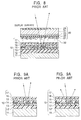
- the reflective layer 12 in the reflector-side substrate 10 can be generally classified into the specular-reflection type and the diffuse-reflection type.
- Fig. 9A shows a specular-reflection type reflective layer 12' and the reflective surface of this reflective layer 12' is made flat so that the absolute value of the incidence angle and the absolute value of the emission angle with respect to the normal of the display surface are the same. Accordingly, when the display surface is observed, there are problems in that the brightness of the display surface varies depending on the positional relationship between the light source and the viewpoint and visibility is degraded due to back reflection, that is, reflection of the light source, the observer's face, etc., in the display surface.
- a diffuse-reflection type reflective layer 12'' shown in Figs. 9B and 10 a plurality of small concavities and convexities (concave portions 31 in Fig. 10) are irregularly formed next to each other on the reflective surface of the reflective layer 12''.
- the diffuse-reflection type reflective layer 12'' external light incident at a certain angle is diffusely reflected by the surface of the reflective layer 12''. Accordingly, it is possible to obtain a reflective liquid crystal display having a wide viewing angle in which brightness does not vary even when the viewpoint is moved and back reflection is reduced.
- a method is known in which light is radiated on the surface of a plate-shaped resin substrate formed of a photosensitive resin layer, etc. through a pattern mask, and a plurality of small, spherical concave portions 31 are formed next to each other by a development process.
- a layer of aluminum, silver, etc. is formed on the surface on which the concave portions are formed by vapor deposition or plating.
- the concave portions 31 are generally formed in a spherical shape whose depth varies in the range of 0.1 ⁇ m to 3 ⁇ m, and distances between the concave portions 31 are set such that the pitch between the concave portions 31 (distance between the central points of the concave portions 31) varies in the range of 5 to 50 ⁇ m.
- FIG. 11A An example of a desk calculator is shown in Fig. 11A, and an example of a mobile computer is shown in Fig. 11B.
- Figs. 11A and 11B when an observer actually views the display surface of a liquid crystal display, he or she often looks up at the display surface from the lower side thereof. More specifically, the viewpoint Ob of the observer is inclined toward the lower side of the display surface by an angle ⁇ relative to the normal X perpendicular to the display surface.
- an object of the present invention is to provide a reflector which appears especially bright when viewed in a specific viewing-angle range and has a light-diffusing characteristic so that back reflection is suppressed over a wide viewing-angle range.
- the present invention provides a reflector including a substrate having a plurality of light-reflective concave portions on the surface thereof, each concave portion having a specific vertical section which passes through a deepest point of the concave portion.
- the internal shape of the specific vertical section is defined by a first curve and a second curve, the first curve extending from one point on the peripheral edge of the concave portion to the deepest point of the concave portion, and the second curve extending continuously from the first curve from the deepest point of the concave portion to another point on the peripheral edge of the concave portion.
- the average of the absolute value of an inclination angle of the first curve relative to the substrate surface is larger than the average of the absolute value of an inclination angle of the second curve relative to the substrate surface.
- the reflector of the present invention a plurality of light-reflective concave portions are formed on the substrate surface, and each of the concave portions has a curved surface (concave surface). Accordingly, the reflector appears bright from a wide viewing area and has a light-diffusing characteristic so that back reflection is suppressed.
- each concave portion along the specific vertical section is defined by the first curve and the second curve which are connected to each other at the deepest point.
- the first and the second curves are formed such that the average of the absolute value of the inclination angle of the first curve relative to the substrate surface is larger than the average of the absolute value of the inclination angle of the second curve relative to the substrate surface. More specifically, the inclination of the first curve is relatively steep and the inclination of the second curve is relatively gentle, and the second curve is longer than the first curve.
- the amount of light reflected by the surface at regions around the second curve is larger than the amount of light reflected by the surface at regions around the first curve. More specifically, luminous flux density of reflection light in the direction of specular reflection relative to the surface at regions around the second curve is increased. Accordingly, when the first curves in each concave portion are aligned in a specific direction (or in a plurality of specific directions), reflectance in the specific direction(s) can be increased over the entire region of the reflector.
- the concave portions are preferably formed such that the specific vertical sections of each concave portion are aligned in the same direction and the orientations of the first curves in each concave portion are the same.
- reflectance in the direction in which light is reflected by the surface at regions around the second curve B is increased over the entire region of the reflector. Accordingly, reflection characteristics in which reflection light is moderately condensed in a specific direction can be obtained.
- the inclination angle of the first curve relative to the substrate surface and the inclination angle of the second curve relative to the substrate surface are preferably zero at the point at which the first curve and the second curve are connected to each other.
- the inclination angle of the first curve is negative and the inclination angle of the second curve is positive, the inclination angle of the first curve is gradually increased from a negative value and the inclination angle of the second curve is gradually reduced from a positive value, and both the inclination angles of the first and second curves become zero at the point at which the first and second curves are connected to each other.
- each concave portion can be made smooth over the entire regions thereof, and reflectance in the direction of specular reflection can be prevented from being reduced.
- the maximum value of the absolute value of the inclination angle of the first curve relative to the substrate surface is preferably in the range of 2° to 90° , and more preferably, in the range of 4° to 35°.
- the maximum inclination angle is preferably determined in accordance with the angle at which an observer views the display surface of the liquid crystal display, it is preferably set in the range of 2° to 90°.
- the maximum inclination angle exceeds 90°, a part of reflection light exceeds the pixel frame of the reflective liquid crystal display and the display surface appears dark.
- the maximum inclination angle is smaller than 2°, the effect of condensing the reflection light in a specific viewing angle becomes insufficient and desired brightness cannot be obtained at a specific viewing angle.
- the maximum inclination angle is preferably set in the range of 4° to 35° in consideration of the viewing angle at which an observer normally views the display surface of the liquid crystal display.
- the concave portions are irregularly formed such that the depth thereof varies in the range of 0.1 ⁇ m to 3 ⁇ m.
- the depths of the concave portions are less than 0.1 ⁇ m, sufficient light-diffusing effect cannot be obtained.
- the depths of the concave portions exceed 3 ⁇ m, the thickness of the substrate, which must be larger than the depths of the concave portions, becomes too large, and disadvantages occur from the viewpoint of manufacturing processes and product quality.
- the concave portions have various depths, a moire-pattern, which often appears due to light interference when the concave portions are formed regularly.
- the reflection light is prevented from being converged too sharply at a predetermined viewing angle and the amount of reflection light smoothly varies in the viewing area.
- the concave portions are irregularly arranged next to each other.
- the concave portions are formed separately, regions at which specular reflection occurs are increased since the regions between the concave portions are flat, and sufficient light-diffusing effect cannot be obtained in the limited pixel area. Accordingly, the concave portions are preferably formed next to each other. In addition, the concave portions are preferably formed irregularly sine the moire-pattern appears when the concave portions are formed regularly.
- the present invention also provides a reflective liquid crystal display which includes one of the above-described reflectors.
- the concave portions are formed such that the specific vertical sections of each concave portion are aligned in the same direction and the orientations of the first curves in each concave portion are the same, and the reflector is installed such that the first curves are disposed above the second curves in each concave portion when viewed by an observer.
- the present invention also provides a reflector in which an integrated value of reflectance in a reflection-angle range smaller than a specular reflection angle with respect to the substrate surface is different from an integrated value of reflectance in a reflection-angle range larger than the specular reflection angle.
- the present invention also provides a reflective liquid crystal display which includes a reflector in which an integrated value of reflectance in a reflection-angle range smaller than a specular reflection angle with respect to the substrate surface is different from an integrated value of reflectance in a reflection-angle range larger than the specular reflection angle.
- the reflector is installed such that the reflection-angle range corresponding to the larger of the integrated values of reflectance is disposed at the upper side of the specular reflection angle with respect to the substrate surface when viewed by an observer.
- external light which is mainly incident from the upper side, can be reflected in the direction shifted toward the normal of the substrate surface from the lower side of the observer.
- the reflective liquid crystal display of the present invention when used as a display for a mobile phone or a notebook computer, the amount of light reflected toward the eyes of the observer is increased, and a reflective liquid crystal display which appears bright from the viewpoint of the observer can be obtained.
- a reflector which has a light-diffusing characteristic so that incident light is diffusely reflected and back reflection is suppressed over a wide viewing angle, and in which the amount of reflection light in the viewing-angle range in which the observer normally views the display is increased.
- a reflective liquid crystal display containing the reflector of the present invention display surface appears especially bright when viewed in a specific viewing-angle range so that visibility is improved, and back reflection is suppressed over a wide viewing-angle range.
- Fig. 1 is a diagram showing a reflector 1 according to an embodiment of the present invention.
- the reflector 1 of the present embodiment is constructed of a plate-shaped substrate 2 formed of, for example, aluminum.
- a plurality of light-reflective concave portions 3a, 3b, 3c, ..., are irregularly formed next to each other on the surface S (standard surface) of the substrate 2.
- Fig. 2 and Fig. 3 are a perspective view and a sectional view, respectively, of the concave portion 3.
- the internal shape of the concave portion 3 along a specific vertical section X is defined by a first curve A and a second curve B, the first curve A extending from one point S1 on the peripheral edge to the deepest point D, and the second curve B extending continuously from the first curve A from the deepest point D to the other point S2 on the peripheral edge.
- Both an inclination angle of the first curve A relative to the substrate surface S and an inclination angle of the second curve B relative to the substrate surface S become zero at the deepest point D, where the first curve A and the second curve B are connected to each other.
- the inclination angle of the first curve A relative to the substrate surface S is steeper than the inclination angle of the second curve B, and the deepest point D is at a position shifted toward the x direction from the central point O of the concave portion 3. More specifically, the average of the absolute value of the inclination angle of the first curve A relative to the substrate surface S is larger than the average of the absolute value of the inclination angle of the second curve B relative to the substrate surface S.
- the average of the absolute value of the inclination angle of the first curve A relative to the substrate surface S in the concave portions 3a, 3b, 3c, ..., varies in the range of 1° to 89°.
- the average of the absolute value of the inclination angle of the second curve B relative to the substrate surface S in the concave portions 3a, 3b, 3c, ... varies in the range of 0.5° to 88°.
- the maximum inclination angle ⁇ max (absolute value) of the first curve A is larger than the maximum inclination angle ⁇ b (absolute value) of the second curve B.
- the inclination angles of the first curve A and the second curve B relative to the substrate surface S both become zero at the deepest point D, where the first curve A and the second curve B are connected to each other. Accordingly, the first curve A, whose inclination angle is negative, and the second curve B, whose inclination angle is positive, are smoothly connected to each other.
- the maximum inclination ⁇ max of the concave portions 3a, 3b, 3c, ... varies in the range of 2° to 90°.
- the maximum inclination ⁇ max of the concave portions 3a, 3b, 3c, ... varies in the range of 4° to 35° .
- each of the concave portions 3 has a single deepest point D (a point at which the inclination angle is zero).
- the distance between the deepest point D and the substrate surface S is defined as the depth of each concave portion 3, and the depth of the concave portions 3a, 3b, 3c, ..., varies in the range of 0.1 ⁇ m to 3 ⁇ m.
- the specific vertical sections X of each of the concave portions 3a, 3b, 3c, ... are aligned in the same direction.
- the orientations of the first curves A in each of the concave portions 3a, 3b, 3c, ... are made the same. More specifically, in every concave portion, the x axis shown in Figs. 2 and 3 extends in the same direction.
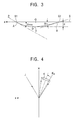
- the orientations of the first curves A in each of the concave portions 3a, 3b, 3c, ..., are made the same. Accordingly, as shown in Fig. 4, the reflection characteristics of the reflector 1 are made such that the reflection direction is shifted from the direction of specular reflection relative to the substrate surface S.
- the reflection light K corresponding to incident light J which is incident at an angle from the upper side of the x direction, is shifted such that a viewing area from which the display appears bright is shifted from the direction of specular reflection K 0 toward the normal H of the substrate surface S.
- the overall reflection characteristics in the specific vertical section X are made such that reflectance in the direction in which light is reflected by the surface at regions around the second curve B is increased. Accordingly, reflection characteristics in which reflection light is moderately condensed in a specific direction can be obtained.
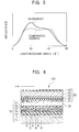
- Fig. 5 shows the relationship between the light-receiving angle ( ⁇ °) and brightness (reflectance) in the case in which external light is radiated onto the display surface of the reflector 1 of the present embodiment under a condition in which the incidence angle is 30°.
- the light-receiving angle is changed from 0° (angle corresponding to the normal) to 60° across the midpoint 30°, which is the specular reflection angle relative to the display surface (substrate surface).
- the relationship between the light-receiving angle and the reflectance in a reflective liquid crystal display containing a known reflector having spherical concave portions is also shown in Fig. 5.
- the reflectance is approximately constant when the light-receiving angle is in the range of 15° to 45°.
- the integrated value of the reflectance in the range in which the light-receiving angle is smaller than the specular reflection angle (30°) is larger than the integrated value of the reflectance in the range in which the light-receiving is larger than the specular reflection angle. More specifically, sufficient brightness can be obtained at viewing angles around 20°.
- the manufacturing method for the reflector 1 is not limited, the reflector 1 can be manufactured by, for example, the following processes.
- a punch stamping tool having a convex end portion corresponding to the shape of the above-described convex portions is prepared.
- the punch is held such that the end portion thereof opposes an aluminum substrate, and is repeatedly pressed against the aluminum substrate so as to form the convex portions over the entire area of a predetermined region of the aluminum substrate. While the punch is repeatedly pressed against the aluminum substrate, the orientation of the punch relative to the aluminum substrate is maintained constant and the stroke and interval are changed irregularly.
- the stroke is adjusted such that the depth of the concave portion is in a predetermined range, and the interval is adjusted such that a moire-pattern does not appear.
- Fig. 6 is a sectional view showing the layer structure of a reflective liquid crystal display 100 containing the reflector 1 of the present embodiment.
- a display-side substrate 20 and a reflector-side substrate 10 oppose each other with a liquid crystal layer 30 therebetween.
- the display-side substrate 20 is transmissive and the reflector-side substrate 10 is reflective.
- the external surface of the display-side substrate 20 serves as a display surface, and the reflector-side substrate 10 is provided with the reflector 1.
- the reflector-side substrate 10 is formed by laminating a glass substrate 11, the reflector 1, a transparent intervening layer 13, a color-filter layer 14, a transparent planarizing layer 15, a transparent electrode layer 16 formed of an Indium Tin Oxide (ITO) film, a Nesa film, etc., and an alignment layer 17, in that order from the bottom.
- the display-side substrate 20, which opposes the reflector-side substrate 10 across the liquid crystal layer 30, is formed by laminating an alignment layer 21, an insulating layer 22, a transparent electrode layer 23 formed of an ITO film, a Nesa film, etc., a glass substrate 24, and a light-modulating layer 25 (a polarizing plate, a retardation plate, etc.) in that order from the liquid crystal layer 30.
- Transparent electrodes of the transparent electrode layer 16 and transparent electrodes of the transparent electrode layer 23 are arranged in striped patterns which perpendicularly cross each other, the liquid crystal layer 30 being disposed therebetween.
- a simple-matrix liquid crystal device is formed in which pixels are formed at intersections of the transparent electrodes of the transparent electrode layer 16 and the transparent electrodes of the alignment layer 17.
- the reflector 1 is aligned such that the first curves A in the concave portions 3a, 3b, 3c, ..., are placed in the x direction relative to the second curves B, which have gentler slopes.
- characters, etc. are displayed in the orientation such that the x direction is aligned with the upward direction.
- Fig. 7 is a diagram showing the manner in which the reflective liquid crystal display 100 is used. In Fig. 7, only the first curves A and the second curves B in the reflective liquid crystal display 100 are shown and other components are omitted for convenience.
- the reflective liquid crystal display 100 is installed in a mobile phone, a notebook computer, etc., in the orientation such that the x direction is aligned with the upward direction.
- the reflective liquid crystal display 100 is normally set or held at an angle relative to the horizontal plane such that the x direction is aligned with the upward direction. More specifically, when the reflective liquid crystal display 100 is used, it is disposed such that the first curves A are above the second curves B in each concave portion when viewed by the observer. In addition, the observer normally looks down onto the reflective liquid crystal display 100 from the upper side relative to the horizontal plane.
- the viewing area from which the observer normally views the display and the viewing area from which the display appears bright are made the same. Therefore, a display device which appears bright from the viewpoint of the observer can be obtained.
- the reflective liquid crystal display according to the present embodiment shown in Fig. 6 is constructed such that the reflector 1 and the transparent electrode layer 16 are formed separately, the transparent electrode layer 16 may also be formed of the reflector 1 and placed at the position where the reflector 1 is formed in Fig. 6. In such a case, the transparent electrode layer also serves as a reflector, and the layer structure of the reflective liquid crystal display can be made simpler.
- the above-described reflector may be formed of a semi-transmissive, semi-reflective substrate such as a half mirror, etc., and an illumination plate may be disposed behind the liquid crystal panel.
- a semi-transmissive, semi-reflective liquid crystal display can be obtained which serves as a reflective type when external light is bright and serves as a transmissive type by illuminating the illumination substrate when external light is dark.
- the present invention may also be applied to such semi-transmissive, semi-reflective liquid crystal displays.
- a front-light liquid crystal display when a front light is disposed in front of the display-side substrate 20, a front-light liquid crystal display can be obtained in which external light is exclusively used when the external light is bright and the front light is optionally used when the external light is dark.
- the present invention may also be applied to such front-light liquid crystal displays.
- the liquid-crystal driving method is not limited in the present invention, and the present invention may also be applied to active-matrix liquid crystal displays using thin film transistors and thin film diodes, segmented liquid crystal displays, etc., in addition to the above-described simple-matrix liquid crystal display.
Landscapes
- Physics & Mathematics (AREA)
- Nonlinear Science (AREA)
- General Physics & Mathematics (AREA)
- Optics & Photonics (AREA)
- Mathematical Physics (AREA)
- Chemical & Material Sciences (AREA)
- Crystallography & Structural Chemistry (AREA)
- Optical Elements Other Than Lenses (AREA)
- Liquid Crystal (AREA)
Applications Claiming Priority (2)
| Application Number | Priority Date | Filing Date | Title |
|---|---|---|---|
| JP2001197360A JP3515544B2 (ja) | 2000-07-03 | 2001-06-28 | 反射体および反射型液晶表示装置 |
| JP2001197360 | 2001-06-28 |
Publications (2)
| Publication Number | Publication Date |
|---|---|
| EP1271187A2 true EP1271187A2 (de) | 2003-01-02 |
| EP1271187A3 EP1271187A3 (de) | 2004-09-22 |
Family
ID=19034979
Family Applications (1)
| Application Number | Title | Priority Date | Filing Date |
|---|---|---|---|
| EP02252646A Ceased EP1271187A3 (de) | 2001-06-28 | 2002-04-15 | Reflektor und reflektierende Flüssigkristallanzeige |
Country Status (5)
| Country | Link |
|---|---|
| US (1) | US6947107B2 (de) |
| EP (1) | EP1271187A3 (de) |
| KR (1) | KR100478574B1 (de) |
| CN (1) | CN1184496C (de) |
| TW (1) | TWI266103B (de) |
Cited By (1)
| Publication number | Priority date | Publication date | Assignee | Title |
|---|---|---|---|---|
| EP1533760A3 (de) * | 2003-11-20 | 2005-08-03 | Aruze Corp. | Anzeigeeinheit und Spielautomat |
Families Citing this family (38)
| Publication number | Priority date | Publication date | Assignee | Title |
|---|---|---|---|---|
| US7176878B2 (en) | 2002-12-11 | 2007-02-13 | Nvidia Corporation | Backlight dimming and LCD amplitude boost |
| US7417782B2 (en) | 2005-02-23 | 2008-08-26 | Pixtronix, Incorporated | Methods and apparatus for spatial light modulation |
| JP2005114772A (ja) * | 2003-10-02 | 2005-04-28 | Alps Electric Co Ltd | 反射体及びこれを用いた液晶表示装置 |
| JP4426355B2 (ja) * | 2004-03-30 | 2010-03-03 | アルプス電気株式会社 | 反射体および液晶表示装置 |
| JP2005321610A (ja) * | 2004-05-10 | 2005-11-17 | Alps Electric Co Ltd | 反射型双安定ネマティック液晶表示装置 |
| US7999994B2 (en) | 2005-02-23 | 2011-08-16 | Pixtronix, Inc. | Display apparatus and methods for manufacture thereof |
| US9082353B2 (en) | 2010-01-05 | 2015-07-14 | Pixtronix, Inc. | Circuits for controlling display apparatus |
| US8159428B2 (en) | 2005-02-23 | 2012-04-17 | Pixtronix, Inc. | Display methods and apparatus |
| US9158106B2 (en) | 2005-02-23 | 2015-10-13 | Pixtronix, Inc. | Display methods and apparatus |
| US8310442B2 (en) | 2005-02-23 | 2012-11-13 | Pixtronix, Inc. | Circuits for controlling display apparatus |
| US7746529B2 (en) | 2005-02-23 | 2010-06-29 | Pixtronix, Inc. | MEMS display apparatus |
| US7675665B2 (en) | 2005-02-23 | 2010-03-09 | Pixtronix, Incorporated | Methods and apparatus for actuating displays |
| US9261694B2 (en) | 2005-02-23 | 2016-02-16 | Pixtronix, Inc. | Display apparatus and methods for manufacture thereof |
| US7616368B2 (en) | 2005-02-23 | 2009-11-10 | Pixtronix, Inc. | Light concentrating reflective display methods and apparatus |
| US7742016B2 (en) | 2005-02-23 | 2010-06-22 | Pixtronix, Incorporated | Display methods and apparatus |
| US7755582B2 (en) | 2005-02-23 | 2010-07-13 | Pixtronix, Incorporated | Display methods and apparatus |
| US9229222B2 (en) | 2005-02-23 | 2016-01-05 | Pixtronix, Inc. | Alignment methods in fluid-filled MEMS displays |
| US8482496B2 (en) | 2006-01-06 | 2013-07-09 | Pixtronix, Inc. | Circuits for controlling MEMS display apparatus on a transparent substrate |
| US7304786B2 (en) | 2005-02-23 | 2007-12-04 | Pixtronix, Inc. | Methods and apparatus for bi-stable actuation of displays |
| US8519945B2 (en) | 2006-01-06 | 2013-08-27 | Pixtronix, Inc. | Circuits for controlling display apparatus |
| US7271945B2 (en) | 2005-02-23 | 2007-09-18 | Pixtronix, Inc. | Methods and apparatus for actuating displays |
| US7502159B2 (en) | 2005-02-23 | 2009-03-10 | Pixtronix, Inc. | Methods and apparatus for actuating displays |
| US7405852B2 (en) | 2005-02-23 | 2008-07-29 | Pixtronix, Inc. | Display apparatus and methods for manufacture thereof |
| US7304785B2 (en) | 2005-02-23 | 2007-12-04 | Pixtronix, Inc. | Display methods and apparatus |
| US20070205969A1 (en) | 2005-02-23 | 2007-09-06 | Pixtronix, Incorporated | Direct-view MEMS display devices and methods for generating images thereon |
| CN100437283C (zh) * | 2005-10-26 | 2008-11-26 | 群康科技(深圳)有限公司 | 背光模组及采用该背光模组的液晶显示装置 |
| US8526096B2 (en) | 2006-02-23 | 2013-09-03 | Pixtronix, Inc. | Mechanical light modulators with stressed beams |
| US7876489B2 (en) | 2006-06-05 | 2011-01-25 | Pixtronix, Inc. | Display apparatus with optical cavities |
| WO2008051362A1 (en) | 2006-10-20 | 2008-05-02 | Pixtronix, Inc. | Light guides and backlight systems incorporating light redirectors at varying densities |
| US9176318B2 (en) | 2007-05-18 | 2015-11-03 | Pixtronix, Inc. | Methods for manufacturing fluid-filled MEMS displays |
| US7852546B2 (en) | 2007-10-19 | 2010-12-14 | Pixtronix, Inc. | Spacers for maintaining display apparatus alignment |
| KR101367136B1 (ko) * | 2007-07-27 | 2014-02-25 | 삼성디스플레이 주식회사 | 유기 발광 표시 장치 및 이의 제조 방법 |
| US8248560B2 (en) | 2008-04-18 | 2012-08-21 | Pixtronix, Inc. | Light guides and backlight systems incorporating prismatic structures and light redirectors |
| US8169679B2 (en) | 2008-10-27 | 2012-05-01 | Pixtronix, Inc. | MEMS anchors |
| KR20120139854A (ko) | 2010-02-02 | 2012-12-27 | 픽스트로닉스 인코포레이티드 | 디스플레이 장치를 제어하기 위한 회로 |
| WO2011097252A2 (en) | 2010-02-02 | 2011-08-11 | Pixtronix, Inc. | Methods for manufacturing cold seal fluid-filled display apparatus |
| US9134552B2 (en) | 2013-03-13 | 2015-09-15 | Pixtronix, Inc. | Display apparatus with narrow gap electrostatic actuators |
| CN106772711B (zh) * | 2017-01-20 | 2020-05-08 | 四川龙华光电薄膜股份有限公司 | 光学膜片 |
Family Cites Families (23)
| Publication number | Priority date | Publication date | Assignee | Title |
|---|---|---|---|---|
| US5101279A (en) * | 1989-12-14 | 1992-03-31 | Canon Kabushiki Kaisha | Liquid crystal display apparatus having lenticular elements oriented in relation to LC pixel aperture dimensions |
| US5128787A (en) * | 1990-12-07 | 1992-07-07 | At&T Bell Laboratories | Lcd display with multifaceted back reflector |
| JP3075134B2 (ja) * | 1995-04-04 | 2000-08-07 | 株式会社日立製作所 | 反射型液晶表示装置 |
| KR100268069B1 (ko) * | 1995-12-11 | 2000-10-16 | 마찌다 가쯔히꼬 | 반사판, 반사판이 결합된 반사형 액정 표시 장치 및 그 제조 방 법 |
| JPH10312165A (ja) | 1997-03-13 | 1998-11-24 | Alps Electric Co Ltd | 反射装置およびこの反射装置を用いた表示装置 |
| KR100299905B1 (ko) * | 1997-03-13 | 2001-09-06 | 가타오카 마사타카 | 반사장치및그제조방법그리고이반사장치를사용한표시장치 |
| KR100692104B1 (ko) * | 1997-06-06 | 2007-12-24 | 스미또모 가가꾸 가부시키가이샤 | 반사형 액정 표시장치 및 광확산 반사판 |
| KR100268005B1 (ko) * | 1997-06-13 | 2000-10-16 | 구본준 | 반사형액정표시소자의반사판및그반사판의제조방법 |
| US6130736A (en) | 1997-06-13 | 2000-10-10 | Alps Electric Co., Ltd. | Liquid crystal display with corrugated reflective surface |
| KR100252438B1 (ko) * | 1997-06-24 | 2000-04-15 | 구본준, 론 위라하디락사 | 반사형액정표시소자의반사판및그것의제조방법 |
| JPH11242105A (ja) * | 1998-02-24 | 1999-09-07 | Alps Electric Co Ltd | 反射体形成用母型とその製造方法および反射体とその製造方法並びに反射型液晶表示装置 |
| TW496992B (en) * | 1997-07-29 | 2002-08-01 | Alps Electric Co Ltd | Reflector having pits and projections on a surface thereof, manufacturing method for the same, and reflection type liquid crystal display device using the same |
| JP3547591B2 (ja) * | 1997-07-29 | 2004-07-28 | アルプス電気株式会社 | 反射体および反射型液晶表示装置 |
| JP3376308B2 (ja) | 1998-03-16 | 2003-02-10 | 株式会社東芝 | 反射板および液晶表示装置 |
| TW386175B (en) * | 1998-05-19 | 2000-04-01 | Dainippon Printing Co Ltd | Light reflective panel for reflective liquid crystal panel |
| JP4292596B2 (ja) | 1998-06-19 | 2009-07-08 | ソニー株式会社 | 拡散反射板及びその製造方法と表示装置 |
| JP2000105370A (ja) * | 1998-09-29 | 2000-04-11 | Matsushita Electric Ind Co Ltd | 反射板、並びに反射型表示素子及びその製造方法 |
| US6163405A (en) * | 1999-04-15 | 2000-12-19 | Industrial Technology Research Institute | Structure of a reflection-type light diffuser in a LCD |
| KR20010039944A (ko) * | 1999-10-01 | 2001-05-15 | 고오사이 아끼오 | 반사판, 반사형 편광판 및 액정 표시 장치 |
| KR100342053B1 (ko) * | 1999-12-14 | 2002-06-27 | 김순택 | 반사형 액정표시장치 |
| KR100603851B1 (ko) * | 2000-02-12 | 2006-07-24 | 엘지.필립스 엘시디 주식회사 | 반사형 액정 표시장치 |
| TW594218B (en) * | 2000-07-03 | 2004-06-21 | Alps Electric Co Ltd | Reflector and reflective liquid crystal display device |
| TW548467B (en) * | 2001-04-19 | 2003-08-21 | Alps Electric Co Ltd | Liquid crystal display device with improved viewing angle property and portable electronic apparatus using the same |
-
2002
- 2002-04-15 EP EP02252646A patent/EP1271187A3/de not_active Ceased
- 2002-05-31 TW TW091111740A patent/TWI266103B/zh not_active IP Right Cessation
- 2002-06-26 US US10/180,577 patent/US6947107B2/en not_active Expired - Fee Related
- 2002-06-26 KR KR10-2002-0036113A patent/KR100478574B1/ko not_active Expired - Fee Related
- 2002-06-27 CN CNB021244103A patent/CN1184496C/zh not_active Expired - Fee Related
Cited By (1)
| Publication number | Priority date | Publication date | Assignee | Title |
|---|---|---|---|---|
| EP1533760A3 (de) * | 2003-11-20 | 2005-08-03 | Aruze Corp. | Anzeigeeinheit und Spielautomat |
Also Published As
| Publication number | Publication date |
|---|---|
| CN1395116A (zh) | 2003-02-05 |
| US6947107B2 (en) | 2005-09-20 |
| KR100478574B1 (ko) | 2005-03-28 |
| US20030001995A1 (en) | 2003-01-02 |
| TWI266103B (en) | 2006-11-11 |
| KR20030003032A (ko) | 2003-01-09 |
| CN1184496C (zh) | 2005-01-12 |
| EP1271187A3 (de) | 2004-09-22 |
Similar Documents
| Publication | Publication Date | Title |
|---|---|---|
| EP1271187A2 (de) | Reflektor und reflektierende Flüssigkristallanzeige | |
| US6606139B2 (en) | Liquid crystal display device with improved viewing angle property and portable electronic apparatus using the same | |
| US6806922B2 (en) | Surface light-emitting device having light-guide panel wherein light radiated from exit surface is maximized proximate to normal direction of exit surface | |
| KR20020021998A (ko) | 액정표시장치 및 반투과형 반사체 | |
| US7321407B2 (en) | Reflector and liquid crystal display | |
| US6829094B2 (en) | Reflector which exhibits good reflectance over wide angle range and liquid crystal display using the same | |
| JP4159886B2 (ja) | 反射体及び液晶表示装置 | |
| KR20020056907A (ko) | 반사 부재 및 광 반사방법 | |
| JP2003015129A (ja) | 液晶表示装置および携帯電子機器 | |
| JP3515544B2 (ja) | 反射体および反射型液晶表示装置 | |
| US7312842B2 (en) | Reflector and liquid crystal display device | |
| US20050073634A1 (en) | Color liquid crystal display device | |
| JP2002328368A (ja) | 反射体および反射型液晶表示装置 | |
| JP4032661B2 (ja) | 液晶装置および電子機器 | |
| JP2007264648A (ja) | 反射体および反射型液晶表示装置 | |
| CN113741734A (zh) | 触控显示面板及显示装置 | |
| JP2004102305A (ja) | 液晶装置および電子機器 | |
| JP2005128071A (ja) | 半透過反射膜およびこれを用いた半透過反射型液晶表示装置 | |
| JP2004126606A (ja) | 液晶装置および電子機器 |
Legal Events
| Date | Code | Title | Description |
|---|---|---|---|
| PUAI | Public reference made under article 153(3) epc to a published international application that has entered the european phase |
Free format text: ORIGINAL CODE: 0009012 |
|
| AK | Designated contracting states |
Kind code of ref document: A2 Designated state(s): AT BE CH CY DE DK ES FI FR GB GR IE IT LI LU MC NL PT SE TR |
|
| AX | Request for extension of the european patent |
Free format text: AL;LT;LV;MK;RO;SI |
|
| PUAL | Search report despatched |
Free format text: ORIGINAL CODE: 0009013 |
|
| AK | Designated contracting states |
Kind code of ref document: A3 Designated state(s): AT BE CH CY DE DK ES FI FR GB GR IE IT LI LU MC NL PT SE TR |
|
| AX | Request for extension of the european patent |
Extension state: AL LT LV MK RO SI |
|
| RIC1 | Information provided on ipc code assigned before grant |
Ipc: 7F 21V 7/09 B Ipc: 7G 02B 5/10 B Ipc: 7G 02B 5/02 B Ipc: 7G 02F 1/1335 A |
|
| 17P | Request for examination filed |
Effective date: 20041211 |
|
| 17Q | First examination report despatched |
Effective date: 20050124 |
|
| AKX | Designation fees paid |
Designated state(s): DE FI FR GB SE |
|
| STAA | Information on the status of an ep patent application or granted ep patent |
Free format text: STATUS: THE APPLICATION HAS BEEN REFUSED |
|
| 18R | Application refused |
Effective date: 20070703 |