EP1271231A2 - Trägerplatte für eine photostimulierbare Speicherleuchtstoffschicht - Google Patents
Trägerplatte für eine photostimulierbare Speicherleuchtstoffschicht Download PDFInfo
- Publication number
- EP1271231A2 EP1271231A2 EP02077392A EP02077392A EP1271231A2 EP 1271231 A2 EP1271231 A2 EP 1271231A2 EP 02077392 A EP02077392 A EP 02077392A EP 02077392 A EP02077392 A EP 02077392A EP 1271231 A2 EP1271231 A2 EP 1271231A2
- Authority
- EP
- European Patent Office
- Prior art keywords
- insert
- edge
- ray cassette
- end member
- insert plate
- Prior art date
- Legal status (The legal status is an assumption and is not a legal conclusion. Google has not performed a legal analysis and makes no representation as to the accuracy of the status listed.)
- Withdrawn
Links
Images


Classifications
-
- B—PERFORMING OPERATIONS; TRANSPORTING
- B32—LAYERED PRODUCTS
- B32B—LAYERED PRODUCTS, i.e. PRODUCTS BUILT-UP OF STRATA OF FLAT OR NON-FLAT, e.g. CELLULAR OR HONEYCOMB, FORM
- B32B3/00—Layered products comprising a layer with external or internal discontinuities or unevennesses, or a layer of non-planar shape; Layered products comprising a layer having particular features of form
- B32B3/10—Layered products comprising a layer with external or internal discontinuities or unevennesses, or a layer of non-planar shape; Layered products comprising a layer having particular features of form characterised by a discontinuous layer, i.e. formed of separate pieces of material
- B32B3/12—Layered products comprising a layer with external or internal discontinuities or unevennesses, or a layer of non-planar shape; Layered products comprising a layer having particular features of form characterised by a discontinuous layer, i.e. formed of separate pieces of material characterised by a layer of regularly- arranged cells, e.g. a honeycomb structure
-
- B—PERFORMING OPERATIONS; TRANSPORTING
- B32—LAYERED PRODUCTS
- B32B—LAYERED PRODUCTS, i.e. PRODUCTS BUILT-UP OF STRATA OF FLAT OR NON-FLAT, e.g. CELLULAR OR HONEYCOMB, FORM
- B32B15/00—Layered products comprising a layer of metal
- B32B15/04—Layered products comprising a layer of metal comprising metal as the main or only constituent of a layer, which is next to another layer of the same or of a different material
-
- B—PERFORMING OPERATIONS; TRANSPORTING
- B32—LAYERED PRODUCTS
- B32B—LAYERED PRODUCTS, i.e. PRODUCTS BUILT-UP OF STRATA OF FLAT OR NON-FLAT, e.g. CELLULAR OR HONEYCOMB, FORM
- B32B7/00—Layered products characterised by the relation between layers; Layered products characterised by the relative orientation of features between layers, or by the relative values of a measurable parameter between layers, i.e. products comprising layers having different physical, chemical or physicochemical properties; Layered products characterised by the interconnection of layers
- B32B7/04—Interconnection of layers
- B32B7/12—Interconnection of layers using interposed adhesives or interposed materials with bonding properties
-
- G—PHYSICS
- G03—PHOTOGRAPHY; CINEMATOGRAPHY; ANALOGOUS TECHNIQUES USING WAVES OTHER THAN OPTICAL WAVES; ELECTROGRAPHY; HOLOGRAPHY
- G03B—APPARATUS OR ARRANGEMENTS FOR TAKING PHOTOGRAPHS OR FOR PROJECTING OR VIEWING THEM; APPARATUS OR ARRANGEMENTS EMPLOYING ANALOGOUS TECHNIQUES USING WAVES OTHER THAN OPTICAL WAVES; ACCESSORIES THEREFOR
- G03B42/00—Obtaining records using waves other than optical waves; Visualisation of such records by using optical means
- G03B42/02—Obtaining records using waves other than optical waves; Visualisation of such records by using optical means using X-rays
- G03B42/04—Holders for X-ray films
-
- G—PHYSICS
- G03—PHOTOGRAPHY; CINEMATOGRAPHY; ANALOGOUS TECHNIQUES USING WAVES OTHER THAN OPTICAL WAVES; ELECTROGRAPHY; HOLOGRAPHY
- G03C—PHOTOSENSITIVE MATERIALS FOR PHOTOGRAPHIC PURPOSES; PHOTOGRAPHIC PROCESSES, e.g. CINE, X-RAY, COLOUR, STEREO-PHOTOGRAPHIC PROCESSES; AUXILIARY PROCESSES IN PHOTOGRAPHY
- G03C3/00—Packages of films for inserting into cameras, e.g. roll-films, film-packs; Wrapping materials for light-sensitive plates, films or papers, e.g. materials characterised by the use of special dyes, printing inks, adhesives
- G03C3/003—Individual packages for X-ray film, e.g. for dental applications
-
- B—PERFORMING OPERATIONS; TRANSPORTING
- B32—LAYERED PRODUCTS
- B32B—LAYERED PRODUCTS, i.e. PRODUCTS BUILT-UP OF STRATA OF FLAT OR NON-FLAT, e.g. CELLULAR OR HONEYCOMB, FORM
- B32B37/00—Methods or apparatus for laminating, e.g. by curing or by ultrasonic bonding
- B32B37/12—Methods or apparatus for laminating, e.g. by curing or by ultrasonic bonding characterised by using adhesives
- B32B37/1207—Heat-activated adhesive
- B32B2037/1215—Hot-melt adhesive
-
- B—PERFORMING OPERATIONS; TRANSPORTING
- B32—LAYERED PRODUCTS
- B32B—LAYERED PRODUCTS, i.e. PRODUCTS BUILT-UP OF STRATA OF FLAT OR NON-FLAT, e.g. CELLULAR OR HONEYCOMB, FORM
- B32B2307/00—Properties of the layers or laminate
- B32B2307/40—Properties of the layers or laminate having particular optical properties
- B32B2307/422—Luminescent, fluorescent, phosphorescent
Definitions
- the present invention relates generally to cassettes for photographic elements, and more particularly, to an x-ray cassette used in computed radiography.
- a photographic element In the field of computed radiography, a photographic element has an image formed thereon by x-rays. The photographic element is subsequently provided to a reader wherein the element is stimulated to emit a radiation pattern that is indicative of the image formed by the x-rays.
- storage phosphors are used to capture radiographic images from incident x-rays. Most radiographic procedures are carried out within normal room lighting conditions, accordingly, a primary requirement for any computed radiography x-ray cassette is to shield the storage phosphor from exposure by ambient light.
- Cassettes of the kind used in computed radiography may comprise a container having an upper and lower parts that are hinged together so that they can be opened for insertion of a flexible film sheet or a rigid film plate comprising the photographic element.
- the cassette is closed and latched so that the cassette with the element therein can be used with an x-ray apparatus to produce an image on the photographic element.
- the cassette is taken to a reader where the cassette is opened and the photographic element extracted by suitable feeders, such as a suction feeding device.
- suitable feeders such as a suction feeding device.
- the photographic element separates from the cassette, and is transported through the reader where it is stimulated to emit a radiation pattern which is captured for storage and use.
- the radiation pattern is subsequently erased from the photographic element before being returned to the cassette for re-use.
- cassettes While such cassettes may have achieved certain degrees of success in their particular applications, cassettes are susceptible to various types of damage when dropped or roughly handled. Accordingly, it is desirable to increase the durability of the cassette while minimizing cost and weight, and preserving the same basic nature of design.
- An object of the present invention is to provide a cassette which has increased durability, and is resistant to damage when dropped or roughly handled.
- a x-ray cassette comprising a shell and a storage phosphor assembly.
- the shell comprises an upper and lower panel, a first and second side member, and a front end member.
- the first and second side members and front end member join the upper and lower panels to define a cavity having an open end.
- the storage phosphor assembly comprises a back end member, an insert plate, and an edge insert.
- the storage phosphor assembly is adapted to be removably contained within the shell such that the back end member closes off the open end of the shell.
- a first side of the edge insert is affixed to the insert plate.
- a first end of the edge insert is disposed adjacent the back end member, and a second end of the edge insert comprises at least one recess on the first side.
- the second end of the edge insert comprises a plurality of spaced recesses.
- the insert plate includes a honeycomb core comprising honeycomb cells wherein the honeycomb cells disposed along a perimeter of the honeycomb core are filled with an adhesive or epoxy.
- the present invention provides a cassette which has increased durability and reduced susceptibility to damage when dropped or roughly handled.
- FIGS 1-4 show a storage phosphor cassette 10 in accordance with the present invention.
- Cassette 10 includes a shell 12 comprising an upper panel 14, a lower panel 16, a first side member 18, a second side member 20, and a front end member 22.
- Upper and lower panels 14,16 are preferably rectangular in shape.
- First side member 18, second side member 20, and front end member 22 join upper and lower panels 14,16 to form a five-sided cavity having an open end 24.
- Cassette 10 further includes a storage phosphor assembly 26 having a front edge 27, a back end member 28, an insert plate 30 having an upper face and being cantilevered from back end member 28, and a storage phosphor 32 disposed on the upper face of insert plate 30.
- a front edge of insert plate 30 includes corners 68,70, which are preferably rounded.
- Back end member 28 includes apertures 29,31 for access to the interior of back end member 28 to latch and unlatch a latch bar 50 slidably mounted therein.
- Storage phosphor assembly 26 is removably contained within the cavity of shell 12 such that back end member 28 of storage phosphor assembly 26 closes off open end 24 of shell 12, thereby providing a light-tight enclosure for storage phosphor 32.
- Back end member 28 of storage phosphor assembly 26 includes end portions 64,66.
- First and second side members 18,20 include a corner structure 60,62, respectively, which respectively engage end portions 64,66.
- Corner structures 60,62 can be integral with first and second side members 18,20, or as illustrated, can be separate corner pieces which are secured to first and second side members 18,20.
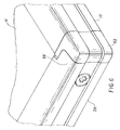
- End portions 64,66 and respective corner structures 60,62 have complimentary, interlocking configurations, such that, should cassette 10 be dropped and a force exerted on either corner structure 60,62, the force is transferred to storage phosphor assembly 26, forcing assembly 26 into shell 12. Corner structure 62 engaged with end portion 66 is further illustrated in Figures 5-6.
- insert plate 30 is comprised of a lightweight rigid structure including an aluminum honeycomb core 71 and outer aluminum skins 72,74.
- the edge of honeycomb core 71 is milled out (recessed) around the entire perimeter to create a cavity.
- edge inserts 76,78,80 are each glued into a side of the cavity formed in the honeycomb structure.
- Back end member 28 is inserted to a fourth side of the cavity formed in the honeycomb structure.
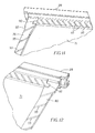
- One end of edge insert 76 interlocks with back end member 28 by means of a connector 90 which can be, for example, a key or leg.
- edge insert 80 interlocks with back end member 28 by means of a connector 92 which can be, for example, key or leg.
- connectors 90,92 are each shown as a leg of back end member 28 extending into edge inserts 76,80 in a direction parallel to the length of back end member 28, which is transverse to the length of edge inserts 76,80, respectively.
- the interlocking arrangement of edge inserts 76,80 with back end member 28 transfers a force from a side impact to cassette 10 to back end member 28 rather than buckling outer aluminum skins 72,74.
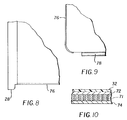
- edge inserts 76,80 may optionally comprise a plurality of shallow slots or channels 93 disposed on at least one of its surfaces. Such channels 93 promote adhesion of the edge inserts with insert plate 30 since they provide additional surface area for the glue to migrate and adhere rather than being directed to the cells of the honeycomb. As illustrated, channels 93 form an angled relative to an edge of edge inserts 76, 80. A cross-hatch pattern might also be employed.
- back end member 28 may also optionally comprise channels 93, with channels 93 being angled relative to an edge of back end member 28.
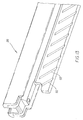
- edge inserts 76,80 extend slightly beyond the perimeter of outer aluminum skins 72,74 (as shown in Figure 3 at 94,96, respectively) thereby creating a shock absorption system to absorb and distribute forces on insert plate 30. If edge inserts 76,80 extend beyond the perimeter of outer aluminum skins 72,74, then preferably channels 93 are disposed on that portion of edge inserts 76,80 which do not extend beyond the perimeter, but rather, are disposed on that portion of edge inserts 76,80 internal to honeycomb core 71.
- edge inserts 76,80 are of aluminum
- edge insert 78 is of a polymeric material
- back end member 28 is of an aluminum material.
- one side of edge inserts 76,80 may comprise a non-planar configuration. That is, a side of edge inserts 76,80 may include at least one groove or recess 100. Recess 100 is disposed at the end of edge inserts 76,80 adjacent edge insert 78. Accordingly, when edge insert 76 or 80 is inserted into insert plate 30, recess 100 promotes adhesion of the edge inserts with insert plate 30 since recess 100 provides additional surface area for the glue to migrate and adhere.
- any exposed (i.e., partially or fully open) cells of honeycomb core 71 disposed along the perimeter of honeycomb core 71 are preferably filled with an adhesive or epoxy material which also fills recesses 100 of edge inserts 76,80.
- the addition of the hardened adhesive or epoxy provides increased stiffness to the edge of honeycomb core 71.
- a filler material other than adhesives and epoxys might be employed to fill the cavities of the cells to provide compressive support structure, for example, liquid materials which harden when cured, adhesives, sealants, surface fillers, potting or encapsulating compounds, and expanding foams.
- adhesives include epoxy adhesives, methacrylate adhesives, urethane adhesives, and hot melt adhesives.
- sealants include silicone sealant, urethane sealant, polysulfide sealant, and acrylic caulk.
- surface fillers and potting compounds include polyester resin with talc powder, epoxy resin with silica, polymeric putties and resin systems.
- expanding foams include two-part liquid expanding urethane foam. If any of these materials include adhesive characteristics, the materials will promote adhesion between the edge inserts with the insert plate in addition to providing structural support.
- the stiffness of the edge of honeycomb core 71 is further enhanced since the linear path for bending/buckling has been reduced/eliminated. That is, there is no longer a linear path for bending or buckling to occur between edge inserts 76,80 and honeycomb core 71, in the event of an impact force or rough handling to cassette 10. Should cassette 10 experience an impact force, the impact force would be directed along the non-linear path where the adhesive (filler material) interfaces to either honeycomb core 71 or recesses 100 in edge inserts 76,80, and since there is no linear path, the likelihood of bending or bucking is reduced/eliminated.
- the additional material filling honeycomb core 71 in conjunction with the non-linear interfaces of the adhesive/epoxy to both honeycomb core 71 and recesses 100 in edge inserts 76,80 reduce/eliminate the likelihood of bending or buckling in that location since the linear interface has been removed, the linear interface being the area likely to fail (i.e., prone to failure).
- a plurality of recesses 100 may be employed in each edge insert 76,80 as illustrated in Figures 14 and 15 wherein five recess 100 are employed with an interstice 102 therebetween.
- each recess 100 may be suitable for the present application with each recess 100 comprising a semi-circular shape having a radius of 0.5 inches and interstice 102 of 0.080 inches.
- recess 100 may comprise a wave, oval, skewed curve, or a linear shape such as a triangle. Fewer or more recesses 100 may be employed than that illustrated in Figures 14 and 15. Similarly, interstice 102 may be greater or smaller than that illustrated.
Landscapes
- Physics & Mathematics (AREA)
- General Physics & Mathematics (AREA)
- Engineering & Computer Science (AREA)
- Microelectronics & Electronic Packaging (AREA)
- Radiography Using Non-Light Waves (AREA)
- Conversion Of X-Rays Into Visible Images (AREA)
Applications Claiming Priority (4)
| Application Number | Priority Date | Filing Date | Title |
|---|---|---|---|
| US896697 | 1986-08-15 | ||
| US09/896,697 US20030001106A1 (en) | 2001-06-29 | 2001-06-29 | Storage phosphor cassette |
| US923186 | 2001-08-06 | ||
| US09/923,186 US6777691B2 (en) | 2001-06-29 | 2001-08-06 | Storage phosphor cassette |
Publications (2)
| Publication Number | Publication Date |
|---|---|
| EP1271231A2 true EP1271231A2 (de) | 2003-01-02 |
| EP1271231A3 EP1271231A3 (de) | 2003-01-22 |
Family
ID=27129153
Family Applications (1)
| Application Number | Title | Priority Date | Filing Date |
|---|---|---|---|
| EP02077392A Withdrawn EP1271231A3 (de) | 2001-06-29 | 2002-06-17 | Trägerplatte für eine photostimulierbare Speicherleuchtstoffschicht |
Country Status (3)
| Country | Link |
|---|---|
| US (1) | US6777691B2 (de) |
| EP (1) | EP1271231A3 (de) |
| JP (1) | JP2003057772A (de) |
Cited By (1)
| Publication number | Priority date | Publication date | Assignee | Title |
|---|---|---|---|---|
| EP1785272A1 (de) * | 2005-09-23 | 2007-05-16 | Homag Holzbearbeitungssysteme AG | Leichtbauplatte und Verfahren zum Verarbeiten einer Leichtbauplatte |
Families Citing this family (3)
| Publication number | Priority date | Publication date | Assignee | Title |
|---|---|---|---|---|
| US6683315B2 (en) * | 2001-06-29 | 2004-01-27 | Eastman Kodak Company | Storage phosphor cassette |
| JP4012182B2 (ja) * | 2004-08-19 | 2007-11-21 | キヤノン株式会社 | カセッテ型x線画像撮影装置 |
| JP6700667B2 (ja) * | 2014-06-18 | 2020-05-27 | キヤノン株式会社 | 放射線撮影装置および放射線撮影システム |
Family Cites Families (8)
| Publication number | Priority date | Publication date | Assignee | Title |
|---|---|---|---|---|
| US4336678A (en) | 1978-07-24 | 1982-06-29 | Peters Dierk D | I-Beam truss structure |
| US5034256A (en) | 1989-08-28 | 1991-07-23 | United Technologies Corporation | Closeout configuration for honeycomb core composite sandwich panels |
| US5276333A (en) * | 1991-11-27 | 1994-01-04 | Eastman Kodak Company | X-ray cassette having removable photographic element |
| EP0584041A1 (de) * | 1992-08-06 | 1994-02-23 | Ciba-Geigy Ag | Profilkantleiste |
| DE69329611T2 (de) | 1992-08-19 | 2001-05-03 | Canon K.K., Tokio/Tokyo | Verfahren zur Registrierung mittels eines projizierenden optischen System, Belichtungsapparat zu dessen Durchführung und sowie Halbleiter-Herstellungsverfahren das diesen Belichtungsapparat verwendet |
| US5869839A (en) | 1997-05-23 | 1999-02-09 | Eastman Kodak Company | Storage phosphor cassette with enhanced features |
| US5861631A (en) | 1997-05-23 | 1999-01-19 | Eastman Kodak Company | Storage phosphor cassette with improved durability |
| US5943390A (en) | 1997-09-30 | 1999-08-24 | Eastman Kodak Company | Storage phosphor cassette with reduced weight and cost |
-
2001
- 2001-08-06 US US09/923,186 patent/US6777691B2/en not_active Expired - Fee Related
-
2002
- 2002-06-14 JP JP2002174283A patent/JP2003057772A/ja active Pending
- 2002-06-17 EP EP02077392A patent/EP1271231A3/de not_active Withdrawn
Cited By (1)
| Publication number | Priority date | Publication date | Assignee | Title |
|---|---|---|---|---|
| EP1785272A1 (de) * | 2005-09-23 | 2007-05-16 | Homag Holzbearbeitungssysteme AG | Leichtbauplatte und Verfahren zum Verarbeiten einer Leichtbauplatte |
Also Published As
| Publication number | Publication date |
|---|---|
| US6777691B2 (en) | 2004-08-17 |
| EP1271231A3 (de) | 2003-01-22 |
| US20030010932A1 (en) | 2003-01-16 |
| JP2003057772A (ja) | 2003-02-26 |
Similar Documents
| Publication | Publication Date | Title |
|---|---|---|
| EP0544138B1 (de) | Röntgenkassette mit herausnehmbarem photographischem Element | |
| US4081686A (en) | X-ray film cassette and method of making same | |
| US7569831B2 (en) | Assembly features and shock protection for a digital radiography detector | |
| US5869839A (en) | Storage phosphor cassette with enhanced features | |
| EP3502749B1 (de) | Strahlungsdetektionsvorrichtung | |
| US5008920A (en) | X-ray film cassette with flexible grid bonded to prestressed cover | |
| EP0905715B1 (de) | Leichte und kostengünstige Speicherleuchtschirmkassette | |
| CN110960236B (zh) | 放射线检测装置 | |
| EP1271232B1 (de) | Speicherleuchtschirmkassette | |
| US5861631A (en) | Storage phosphor cassette with improved durability | |
| US6777691B2 (en) | Storage phosphor cassette | |
| US5652781A (en) | Intensifying x-ray film cassette | |
| EP1315030B1 (de) | Digitale Radiographiekassette für Mammographie | |
| US20030001106A1 (en) | Storage phosphor cassette | |
| US6719457B2 (en) | Radiation cassette and method of manufacturing same | |
| EP1271230B1 (de) | Speicherphosphorkassette mit stossdämpfenden Eckelementen | |
| JPS61228399A (ja) | 放射線像変換パネルおよびその製法 | |
| JP2003190131A (ja) | X線透過エッジを有するコンピューテッドラジオグラフィカセッテ | |
| CA2121975A1 (en) | Film cassette | |
| US20190196032A1 (en) | Radiation detection device | |
| JP6826974B2 (ja) | 放射線検出装置 | |
| US7087909B2 (en) | Storage phosphor cassette | |
| EP1709482A1 (de) | Kassette für flexible speicherleuchtstoffmedien | |
| JP2004145073A (ja) | 放射線画像撮影装置 |
Legal Events
| Date | Code | Title | Description |
|---|---|---|---|
| PUAI | Public reference made under article 153(3) epc to a published international application that has entered the european phase |
Free format text: ORIGINAL CODE: 0009012 |
|
| PUAL | Search report despatched |
Free format text: ORIGINAL CODE: 0009013 |
|
| AK | Designated contracting states |
Kind code of ref document: A2 Designated state(s): AT BE CH CY DE DK ES FI FR GB GR IE IT LI LU MC NL PT SE TR |
|
| AX | Request for extension of the european patent |
Free format text: AL;LT;LV;MK;RO;SI |
|
| AK | Designated contracting states |
Kind code of ref document: A3 Designated state(s): AT BE CH CY DE DK ES FI FR GB GR IE IT LI LU MC NL PT SE TR |
|
| AX | Request for extension of the european patent |
Free format text: AL;LT;LV;MK;RO;SI |
|
| RIC1 | Information provided on ipc code assigned before grant |
Free format text: 7G 03B 42/04 A, 7G 03C 3/00 B, 7B 32B 3/02 B |
|
| 17P | Request for examination filed |
Effective date: 20030704 |
|
| 17Q | First examination report despatched |
Effective date: 20030806 |
|
| AKX | Designation fees paid |
Designated state(s): DE FR GB |
|
| GRAP | Despatch of communication of intention to grant a patent |
Free format text: ORIGINAL CODE: EPIDOSNIGR1 |
|
| STAA | Information on the status of an ep patent application or granted ep patent |
Free format text: STATUS: THE APPLICATION IS DEEMED TO BE WITHDRAWN |
|
| 18D | Application deemed to be withdrawn |
Effective date: 20060223 |