EP1271697A1 - Borne à vis - Google Patents
Borne à vis Download PDFInfo
- Publication number
- EP1271697A1 EP1271697A1 EP20020077305 EP02077305A EP1271697A1 EP 1271697 A1 EP1271697 A1 EP 1271697A1 EP 20020077305 EP20020077305 EP 20020077305 EP 02077305 A EP02077305 A EP 02077305A EP 1271697 A1 EP1271697 A1 EP 1271697A1
- Authority
- EP
- European Patent Office
- Prior art keywords
- screw
- head
- pressure
- pressure piece
- terminal according
- Prior art date
- Legal status (The legal status is an assumption and is not a legal conclusion. Google has not performed a legal analysis and makes no representation as to the accuracy of the status listed.)
- Granted
Links
- 239000004020 conductor Substances 0.000 claims abstract description 12
- 230000006835 compression Effects 0.000 claims description 4
- 238000007906 compression Methods 0.000 claims description 4
- 230000014759 maintenance of location Effects 0.000 claims 1
- 230000006837 decompression Effects 0.000 description 1
- 230000007423 decrease Effects 0.000 description 1
- 230000000694 effects Effects 0.000 description 1
- 230000002349 favourable effect Effects 0.000 description 1
- 238000009413 insulation Methods 0.000 description 1
- 238000012423 maintenance Methods 0.000 description 1
- 239000002184 metal Substances 0.000 description 1
Images
Classifications
-
- H—ELECTRICITY
- H01—ELECTRIC ELEMENTS
- H01R—ELECTRICALLY-CONDUCTIVE CONNECTIONS; STRUCTURAL ASSOCIATIONS OF A PLURALITY OF MUTUALLY-INSULATED ELECTRICAL CONNECTING ELEMENTS; COUPLING DEVICES; CURRENT COLLECTORS
- H01R4/00—Electrically-conductive connections between two or more conductive members in direct contact, i.e. touching one another; Means for effecting or maintaining such contact; Electrically-conductive connections having two or more spaced connecting locations for conductors and using contact members penetrating insulation
- H01R4/28—Clamped connections, spring connections
- H01R4/48—Clamped connections, spring connections utilising a spring, clip, or other resilient member
- H01R4/489—Clamped connections, spring connections utilising a spring, clip, or other resilient member spring force increased by screw, cam, wedge, or other fastening means
-
- H—ELECTRICITY
- H01—ELECTRIC ELEMENTS
- H01R—ELECTRICALLY-CONDUCTIVE CONNECTIONS; STRUCTURAL ASSOCIATIONS OF A PLURALITY OF MUTUALLY-INSULATED ELECTRICAL CONNECTING ELEMENTS; COUPLING DEVICES; CURRENT COLLECTORS
- H01R4/00—Electrically-conductive connections between two or more conductive members in direct contact, i.e. touching one another; Means for effecting or maintaining such contact; Electrically-conductive connections having two or more spaced connecting locations for conductors and using contact members penetrating insulation
- H01R4/28—Clamped connections, spring connections
- H01R4/30—Clamped connections, spring connections utilising a screw or nut clamping member
- H01R4/36—Conductive members located under tip of screw
- H01R4/363—Conductive members located under tip of screw with intermediate part between tip and conductive member
-
- Y—GENERAL TAGGING OF NEW TECHNOLOGICAL DEVELOPMENTS; GENERAL TAGGING OF CROSS-SECTIONAL TECHNOLOGIES SPANNING OVER SEVERAL SECTIONS OF THE IPC; TECHNICAL SUBJECTS COVERED BY FORMER USPC CROSS-REFERENCE ART COLLECTIONS [XRACs] AND DIGESTS
- Y10—TECHNICAL SUBJECTS COVERED BY FORMER USPC
- Y10T—TECHNICAL SUBJECTS COVERED BY FORMER US CLASSIFICATION
- Y10T403/00—Joints and connections
- Y10T403/70—Interfitted members
- Y10T403/7041—Interfitted members including set screw
Definitions
- the present invention relates to a screw terminal associated with a conductive part an electrical apparatus for connecting at least one electrical conductor to this part.
- a screw terminal of the type comprising a connection cage equipped with a tapped hole, a screw having a head and a threaded tail cooperating with the threaded orifice, and a piece of elastic pressure which must apply on the electrical conductor.
- the cage and / or the screw are movable in a housing, and the pressure piece includes a headband and a pressure range interconnected by a resilient elastic wing to store a clamping energy, the head range can be solicited by the screw head and the pressure range being applicable against a conductor or against the conductive part of the device.
- a pressure piece in U-shaped stirrup shape comprising a high wing and a low wing connected by a soul, is engaged by the high wing under the head of the screw and is applicable by the wing low against a driver introduced into the cage; the soul of the stirrup is a bit more high than the length of the threaded portion to provide a pressurized the room.
- This pressurization allows, by the support exerted under the screw head, to avoid loosening the terminal and / or, after applying the screw foot against the wing low, to catch the creep of the driver tightened by the terminal.
- the U-shape of the pressure piece causes an imbalance during the implementation of the terminal.
- Document DE 40 13 225 also illustrates a screw terminal provided with a piece of closed cage pressure whose mode of deformation is not specified.
- the object of the invention is to improve the balancing of a screw terminal of the type described, while by providing the pressure piece with an advantageous mode of deformation both for the congestion of the terminal that for the respect of the elastic limit of the room of pressure.
- the pressure piece comprises two symmetrical elastic wings relative to an axial plane of the screw, the elastic wings are of concave shape and the headband is solicited by the screw head so as to symmetrically pressure piece in compression when tightening the screw.
- the pressure piece advantageously forms an interlaced ring with the rigid cage.
- the arrangement of the pressure piece is preferably such that the elastic wings concaves are deformed with a concavity which is reduced when the constraint exerted by the screw increases.
- the headband has a sloping or convex shape, and the screw head biases the head range a short distance from the axis of the screw, so to promote the indicated effect of reducing lateral concavity.
- the room pressure can be engaged on the neck of the screw by means of a mounting range to two circular half-sectors and may comprise - or cooperate with - elements Keeping the terminal in the open position and improved insulation on the side of the introduction opening of the driver.
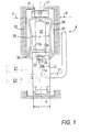
- Figure 1 is a schematic partial sectional view of the screw terminal according to the invention.
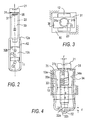
- Figure 2 is a side view of the terminal of Figure 1.
- FIG. 3 is a view from above of the terminal of FIG. 1, with partial section according to III-III.
- Figure 4 illustrates the operation of the screw terminal.
- the screw terminal A shown is intended to be housed in an electrical device.
- the only elements of the apparatus shown in FIG. 1 are the insulating housing 10 provided for the terminal and a fixed branch of contact of the conductive electrical part rigid 11 against which it is desired to tighten one or more conductors; thus, two drivers C1, C2 may be introduced respectively above and below the branch are shown in Figure 1.
- Housing 10 is located in the device, this means that it is provided in a part of the housing of the device or in a terminal box attached to the housing of the device.
- Terminal A comprises a cage 12 of well-known type, formed by a portion of metal strip cut and folded to curl into a rigid ring and substantially rectangular.
- the rigid cage 12 has on a small side 12a a threaded orifice 12b and the contact leg of the conductive part 11 is engaged transversely in the elongate opening 12c, for example substantially rectangular, of the cage 12.
- the screw 20 comprises an operating head 21, a threaded rod 22 and a neck 23 connecting the threaded rod to the head.
- a pressure piece 30 is coupled to the screw 20 so as to move with she.
- the piece 30 is an elastic unitary piece, substantially closed on itself ring-shaped and symmetrical with respect to an axial plane P of the screw.
- She comprises a head area 31 located under the head 21 and enclosing the neck 23 of the screw, a pressure range 32 applicable on the driver C1 or the branch of contact of the conductive part 11 and, on each side of the axis of the screw, a wing concave 33,34 which is connected to the ranges 31,32 by a connection zone defining a protruding angle 35.
- the concavity of the wings see this concavity in view lateral view in FIGS.
- the head beach 31 comprises two circular half-sectors 31a, 31b which engage in the neck 23 of the screw and thus ensure a balanced maintenance of the 30.
- the half-sectors comprising the head region 31 are oriented so as to go back to the head of the screw, giving a generally sloping or convex shape to the head beach, and the beach 31 ends beyond the half-sectors by drawdowns axial contiguous 31 c which meet in the axial plane P of the screw.
- the pressure range 32 is curved to give a generally convex shape to the lower part of the piece 30 and has reliefs 32a cooperating with a part recessed 11a of the conductive part 11.
- the part 30 is arranged so that the concavity of its wings 33,34, in combination with the sloping or convex shape of its ranges 31,32, allows it to deform by compression, with a curvature that decreases as the pressure increases.
- the concavity of reduction is accompanied by the holding part 30 in the template defined by the sharp edges 35, this template being itself - by necessity guide - less than the width b of the housing 10.
- a small distance c is provided between the bearing surface 24 of the screw and the internal face 32a of the pressure range 32, this distance c being determined so that its catching produces the desired level of stress of the pressure piece.
- the minimum distance d (observed at rest) between the inner faces 33a, 34a of the wings 33,34 is slightly greater than the width e of the cage 12, so that the cage can slide freely between the wings or vice versa.
- the head 21 of the screw is applied to the head region 31 of the pressure member in a region at a short distance f from the axis of the screw, so as to create via the range 31 a lever arm which accentuates the torque exerted on the piece 30.
- the insulating housing 10 has on its inner walls at least one protrusion of 10a that cooperates with the advance formed at the upper corner of the room pressure to hold the terminal in the open position.
- an insulating bib 36 which reduces the risk of inadvertent contact is fixed on the wing 34, so as to move with the pressure piece and partially obscure an opening opening of driver. Punctured zones of decompression 36 can be provided in the region strongly stressed angles 35.
- the screw head urges the head range in compression, which is favorable to respect the elastic limit of the part 30.
- the elastic force stored in the wings 33,34 of the part 30 helps to prevent a loosening the screw by inadvertent rotation (action exerted by the head region 31 on the head 21) and catching a clearance due to the creep of the driver C1, by moving the pressure range 32 relative to the span 24 of the screw, with an amplitude up to c .
Landscapes
- Connections By Means Of Piercing Elements, Nuts, Or Screws (AREA)
- Connections Arranged To Contact A Plurality Of Conductors (AREA)
Abstract
Description
Claims (8)
- Borne à vis associée à une pièce conductrice d'un appareil électrique pour lui connecter au moins un conducteur électrique, comprenant une cage de connexion (12) dotée d'un orifice taraudé, une vis (20) présentant une tête et une queue filetée coopérant avec l'orifice taraudé, la cage et/ou la vis étant déplaçable dans un logement de l'appareil, et une pièce de pression (30) comprenant une plage de tête (31) et une plage de pression (32) reliées entre elles par une aile élastique propre à emmagasiner une énergie de serrage, la plage de tête étant assujettie sous la tête de vis et la plage de pression étant applicable contre un conducteur ou contre la pièce conductrice de l'appareil,
caractérisée par le fait quela pièce de pression (30) comprend deux ailes élastiques (33,34) symétriques par rapport à un plan axial (P) de la vis (20),les ailes élastiques (33,34) sont de forme concave,la plage de tête (31) est sollicitée par la tête de vis (21) pour mettre symétriquement la pièce de pression (30) en compression lors du serrage de la vis. - Borne selon la revendication 1, caractérisée par le fait que l'agencement de la pièce de pression (30) est tel que les ailes élastiques concaves (33,34) se déforment avec réduction de leur courbure quand la contrainte exercée par la vis (20) augmente.
- Borne selon la revendication 1, caractérisée par le fait que la plage de tête (31) de la pièce de pression (30) présente vers la tête (21) de la vis (20) une forme pentue ou convexe et que la tête de vis sollicite la plage de tête à faible distance (f) de l'axe de la vis.
- Borne selon la revendication 1, caractérisée par le fait que la plage de pression (32) de la pièce de pression (30) présente vers la pièce conductrice (11) une forme convexe.
- Borne selon la revendication 1, caractérisée par le fait que la plage de tête (31) de la pièce de pression (30) présente deux demi-secteurs circulaires (31a,31b) s'engageant sur un col (23) de la vis (20) et se termine par des rabattements jointifs (31c).
- Borne selon la revendication 1, caractérisée par le fait que la pièce de pression (30) forme un anneau entrelacé avec la cage (12), la distance minimale (d) entre les faces internes des ailes concaves (33,34) de la pièce de pression étant légèrement supérieure à la largeur de la cage.
- Borne selon la revendication 1, caractérisée par le fait que la zone de raccordement d'une aile élastique concave avec la plage de tête forme un angle saillant (35) qui coopère avec un relief (10a) de maintien prévu à l'intérieur du logement de la borne pour retenir celle-ci en position ouverte.
- Borne selon la revendication 1, caractérisée par le fait qu'une bavette isolante est fixée à une aile concave (34) de la pièce de pression.
Applications Claiming Priority (2)
| Application Number | Priority Date | Filing Date | Title |
|---|---|---|---|
| FR0107624 | 2001-06-06 | ||
| FR0107624A FR2825838B1 (fr) | 2001-06-06 | 2001-06-06 | Borne a vis |
Publications (2)
| Publication Number | Publication Date |
|---|---|
| EP1271697A1 true EP1271697A1 (fr) | 2003-01-02 |
| EP1271697B1 EP1271697B1 (fr) | 2015-08-12 |
Family
ID=8864187
Family Applications (1)
| Application Number | Title | Priority Date | Filing Date |
|---|---|---|---|
| EP02077305.7A Expired - Lifetime EP1271697B1 (fr) | 2001-06-06 | 2002-06-04 | Borne à vis |
Country Status (6)
| Country | Link |
|---|---|
| US (1) | US6719593B2 (fr) |
| EP (1) | EP1271697B1 (fr) |
| JP (1) | JP4060128B2 (fr) |
| CN (1) | CN1271747C (fr) |
| ES (1) | ES2548058T3 (fr) |
| FR (1) | FR2825838B1 (fr) |
Cited By (1)
| Publication number | Priority date | Publication date | Assignee | Title |
|---|---|---|---|---|
| EP2383841A2 (fr) | 2010-04-30 | 2011-11-02 | Schneider Electric Industries SAS | Système de raccordement permettant de signaler le couple de serrage d'une borne à vis |
Families Citing this family (10)
| Publication number | Priority date | Publication date | Assignee | Title |
|---|---|---|---|---|
| TWI263384B (en) | 2002-12-19 | 2006-10-01 | Fuji Electric Co Ltd | Terminal device for electrical equipment |
| CN101246999B (zh) * | 2007-02-14 | 2011-03-30 | 吴智远 | 导线端子座的夹线座与其齿部加工方法 |
| US7404745B1 (en) * | 2007-04-03 | 2008-07-29 | Chih-Yuan Wu | Terminal contact and clamp assembly for a cable terminal block and method for processing the same |
| CN101641831B (zh) * | 2007-04-03 | 2012-07-25 | 西门子公司 | 导电体尤其是带有线鼻子的导电体的连接夹紧装置 |
| FR2986664B1 (fr) * | 2012-02-03 | 2014-02-14 | Abb France | Borne de raccordement electrique |
| FR3012685B1 (fr) * | 2013-10-29 | 2017-10-20 | Schneider Electric Ind Sas | Borne de serrage d'une connexion electrique |
| US9812829B1 (en) | 2016-11-10 | 2017-11-07 | Schneider Electric USA, Inc. | Wiring connector for two wire to two point connection |
| WO2020157563A2 (fr) * | 2019-01-29 | 2020-08-06 | Appleton Grp, Llc | Gaine d'absorption de chaleur et de dissipation de chaleur pour un terminal d'un dispositif électrique |
| DE102021112258A1 (de) | 2021-05-11 | 2022-11-17 | Weidmüller Interface GmbH & Co. KG | Anschlussvorrichtung |
| DE202022103614U1 (de) * | 2022-06-29 | 2022-11-23 | Raycap Ip Development Ltd. | Modulare Überspannungsschutzgerätanordnungen und elektrische Anlagen, die diese beinhalten |
Citations (9)
| Publication number | Priority date | Publication date | Assignee | Title |
|---|---|---|---|---|
| NL63870C (fr) * | 1900-01-01 | |||
| DE712382C (de) * | 1940-05-07 | 1941-10-17 | Walter Luedicke | Anschluss- oder Verbindungsklemme fuer elektrische Leiter |
| DE733024C (de) * | 1939-11-05 | 1943-03-17 | Versuchsanstalt Fuer Luftfahrt | Federnde Klemme, insbesondere fuer Leichtmetalleitungen |
| CH325260A (de) * | 1953-07-08 | 1957-10-31 | Siemens Ag | Klemme mit federndem Rahmen, insbesondere für Leichtmetall-Leitungen |
| DE1935560U (de) | 1964-02-21 | 1966-03-31 | Georg Schlegel Elektrotechnisc | Anschlussklemme fuer einen oder mehrere elektrische leiter. |
| DE2147046A1 (de) * | 1971-09-21 | 1973-04-05 | Phoenix Elekt | Elektrische verbindungsklemme, insbesondere hochstrom-reihenklemme |
| DE4013225A1 (de) | 1990-04-26 | 1991-10-31 | Abb Patent Gmbh | Schraubanschlussklemme, insbesondere fuer ein an gleiche oder gleichartige geraete anreihbares schaltgeraet |
| DE4102581A1 (de) | 1991-01-29 | 1992-08-06 | Siemens Ag | Reihenklemme |
| EP0865128A1 (fr) * | 1997-03-10 | 1998-09-16 | Siemens Aktiengesellschaft | Système de distribution |
Family Cites Families (14)
| Publication number | Priority date | Publication date | Assignee | Title |
|---|---|---|---|---|
| US2602104A (en) * | 1946-08-13 | 1952-07-01 | Hubbell Inc Harvey | Wire connector for electrical receptacles |
| US2809363A (en) * | 1954-08-21 | 1957-10-08 | Siemens Ag | Electrical connectors |
| US3659253A (en) * | 1970-02-28 | 1972-04-25 | Siemens Ag | Frame clamp for electrically connecting electrical leads |
| US3836914A (en) * | 1972-12-20 | 1974-09-17 | Mead Corp | Catcher for a jet drop recorder |
| US3836941A (en) * | 1973-07-05 | 1974-09-17 | Thomas & Betts Corp | Electrical connector with resilient pressure pad |
| US3864005A (en) * | 1973-10-11 | 1975-02-04 | Gen Electric | Resilient electrical terminal connector |
| US4103986A (en) * | 1977-09-12 | 1978-08-01 | Thomas & Betts Corporation | Electrical terminal |
| US4213669A (en) * | 1978-09-11 | 1980-07-22 | Gte Sylvania Wiring Devices Incorporated | Terminal collar |
| DE3412317A1 (de) * | 1984-04-03 | 1985-10-03 | C.A. Weidmüller GmbH & Co, 4930 Detmold | Leiteranschluss fuer kaschierte leiterplatten |
| DE69423658T2 (de) * | 1994-12-09 | 2000-07-13 | Jonan Denki Seiki Ltd., Tokio/Tokyo | Anschlussblock |
| US5747741A (en) * | 1995-06-16 | 1998-05-05 | Hubert Laurenz Naimer | Screw terminal for an electrical connection of cables or wires |
| US6040525A (en) * | 1996-04-18 | 2000-03-21 | Erico International Corporation | Electrical clip and method |
| US6004197A (en) * | 1997-01-23 | 1999-12-21 | Hao Chien Chao | Ergonomically friendly random orbital sander construction |
| DE19716762C2 (de) * | 1997-04-12 | 2002-02-28 | Wago Verwaltungs Gmbh | Schirmanschlußklemme |
-
2001
- 2001-06-06 FR FR0107624A patent/FR2825838B1/fr not_active Expired - Fee Related
-
2002
- 2002-06-04 EP EP02077305.7A patent/EP1271697B1/fr not_active Expired - Lifetime
- 2002-06-04 ES ES02077305.7T patent/ES2548058T3/es not_active Expired - Lifetime
- 2002-06-06 JP JP2002165506A patent/JP4060128B2/ja not_active Expired - Lifetime
- 2002-06-06 CN CNB021410143A patent/CN1271747C/zh not_active Expired - Fee Related
- 2002-06-06 US US10/162,567 patent/US6719593B2/en not_active Expired - Lifetime
Patent Citations (9)
| Publication number | Priority date | Publication date | Assignee | Title |
|---|---|---|---|---|
| NL63870C (fr) * | 1900-01-01 | |||
| DE733024C (de) * | 1939-11-05 | 1943-03-17 | Versuchsanstalt Fuer Luftfahrt | Federnde Klemme, insbesondere fuer Leichtmetalleitungen |
| DE712382C (de) * | 1940-05-07 | 1941-10-17 | Walter Luedicke | Anschluss- oder Verbindungsklemme fuer elektrische Leiter |
| CH325260A (de) * | 1953-07-08 | 1957-10-31 | Siemens Ag | Klemme mit federndem Rahmen, insbesondere für Leichtmetall-Leitungen |
| DE1935560U (de) | 1964-02-21 | 1966-03-31 | Georg Schlegel Elektrotechnisc | Anschlussklemme fuer einen oder mehrere elektrische leiter. |
| DE2147046A1 (de) * | 1971-09-21 | 1973-04-05 | Phoenix Elekt | Elektrische verbindungsklemme, insbesondere hochstrom-reihenklemme |
| DE4013225A1 (de) | 1990-04-26 | 1991-10-31 | Abb Patent Gmbh | Schraubanschlussklemme, insbesondere fuer ein an gleiche oder gleichartige geraete anreihbares schaltgeraet |
| DE4102581A1 (de) | 1991-01-29 | 1992-08-06 | Siemens Ag | Reihenklemme |
| EP0865128A1 (fr) * | 1997-03-10 | 1998-09-16 | Siemens Aktiengesellschaft | Système de distribution |
Cited By (4)
| Publication number | Priority date | Publication date | Assignee | Title |
|---|---|---|---|---|
| EP2383841A2 (fr) | 2010-04-30 | 2011-11-02 | Schneider Electric Industries SAS | Système de raccordement permettant de signaler le couple de serrage d'une borne à vis |
| FR2959613A1 (fr) * | 2010-04-30 | 2011-11-04 | Schneider Electric Ind Sas | Systeme de raccordement permettant de signaler le couple de serrage d'une borne a vis. |
| EP2383841A3 (fr) * | 2010-04-30 | 2012-03-28 | Schneider Electric Industries SAS | Système de raccordement permettant de signaler le couple de serrage d'une borne à vis |
| US8393922B2 (en) | 2010-04-30 | 2013-03-12 | Schneider Electric Industries Sas | Connection system enabling the tightening torque of a screw terminal to be indicated |
Also Published As
| Publication number | Publication date |
|---|---|
| US6719593B2 (en) | 2004-04-13 |
| JP2003223942A (ja) | 2003-08-08 |
| FR2825838A1 (fr) | 2002-12-13 |
| EP1271697B1 (fr) | 2015-08-12 |
| CN1271747C (zh) | 2006-08-23 |
| FR2825838B1 (fr) | 2006-12-29 |
| JP4060128B2 (ja) | 2008-03-12 |
| US20020187685A1 (en) | 2002-12-12 |
| ES2548058T3 (es) | 2015-10-13 |
| CN1389957A (zh) | 2003-01-08 |
Similar Documents
| Publication | Publication Date | Title |
|---|---|---|
| EP1271697B1 (fr) | Borne à vis | |
| EP2007991B1 (fr) | Dispositif de serrage | |
| EP0571294B1 (fr) | Collier de serrage à vis | |
| EP0688063B1 (fr) | Appareil électrique muni d'une borne à vis | |
| EP2430321B1 (fr) | Dispositif pour fixer une premiere piece sur une deuxieme piece qui est elle-meme fixee sur une troisieme piece, assemblage de trois pieces en particulier d'un vehicule automobile | |
| EP1531519B1 (fr) | Borne de raccordement électrique et appareil de protection électrique comportant une telle borne | |
| EP0559585A1 (fr) | Borne de raccordement à étrier d'épaisseur variable et à écrou serti | |
| EP1231422B1 (fr) | Procédé pour rendre une vis imperdable, collier de fixation de tuyauteries et utilisation du procédé pour fabriquer les colliers | |
| EP0326481A1 (fr) | Ecrou en forme de pince et assemblage réalisé à l'aide de cet écrou | |
| FR2862441A1 (fr) | Serre-cable a plage de serrage elargie et bloc de jonction muni d'un tel serre-cable | |
| FR2579026A2 (fr) | Dispositif de raccord pour une embase d'antenne destinee a etre fixee sur une paroi et capuchon d'antiparasitage pour un tel dispositif | |
| FR2722546A1 (fr) | Vis a tete encagee pour montage en aveugle dans l'ouverture d'un panneau par example | |
| FR2799312A1 (fr) | Borne de connexion electrique | |
| FR2908239A1 (fr) | "dispositif de serrage et de maintien de cable" | |
| EP2034559B1 (fr) | Dispositif de connexion électrique, application et procédé d'utilisation | |
| FR2619252A1 (fr) | Systeme de liaison a joint pour elements travaillant en hyperfrequence | |
| EP0724107B1 (fr) | Collier de serrage à réglage instantané | |
| EP2115817B1 (fr) | Bloc de jonction comprenant des moyens de retenue d'une barrette conductrice | |
| FR3157696A1 (fr) | Bouchon à tige pour assurer une fixation de busbarre électrique et une étanchéité | |
| EP0109338B1 (fr) | Système de serrage de câbles | |
| EP1607644A2 (fr) | Articulation rotulante et application d'une telle articulation pour une commande d'embrayage | |
| FR2613877A1 (fr) | Cosse de raccordement electrique | |
| FR2966648A1 (fr) | Cable electrique a cosse a fut serti a protuberance de retenue de gaine d'etancheite thermo-retractee | |
| FR2776842A3 (fr) | Element de contact a bras elastique | |
| FR2894721A1 (fr) | Etrier de serrage a vis imperdable pour raccorder deux conducteurs |
Legal Events
| Date | Code | Title | Description |
|---|---|---|---|
| PUAI | Public reference made under article 153(3) epc to a published international application that has entered the european phase |
Free format text: ORIGINAL CODE: 0009012 |
|
| AK | Designated contracting states |
Kind code of ref document: A1 Designated state(s): AT BE CH CY DE DK ES FI FR GB GR IE IT LI LU MC NL PT SE TR |
|
| AX | Request for extension of the european patent |
Free format text: AL;LT;LV;MK;RO;SI |
|
| 17P | Request for examination filed |
Effective date: 20030127 |
|
| AKX | Designation fees paid |
Designated state(s): CH DE ES FR IT LI |
|
| RAP1 | Party data changed (applicant data changed or rights of an application transferred) |
Owner name: SCHNEIDER ELECTRIC INDUSTRIES SAS |
|
| 17Q | First examination report despatched |
Effective date: 20100722 |
|
| GRAP | Despatch of communication of intention to grant a patent |
Free format text: ORIGINAL CODE: EPIDOSNIGR1 |
|
| INTG | Intention to grant announced |
Effective date: 20150513 |
|
| GRAS | Grant fee paid |
Free format text: ORIGINAL CODE: EPIDOSNIGR3 |
|
| GRAA | (expected) grant |
Free format text: ORIGINAL CODE: 0009210 |
|
| AK | Designated contracting states |
Kind code of ref document: B1 Designated state(s): CH DE ES FR IT LI |
|
| REG | Reference to a national code |
Ref country code: CH Ref legal event code: EP |
|
| REG | Reference to a national code |
Ref country code: DE Ref legal event code: R096 Ref document number: 60247378 Country of ref document: DE |
|
| REG | Reference to a national code |
Ref country code: ES Ref legal event code: FG2A Ref document number: 2548058 Country of ref document: ES Kind code of ref document: T3 Effective date: 20151013 |
|
| REG | Reference to a national code |
Ref country code: FR Ref legal event code: PLFP Year of fee payment: 15 |
|
| REG | Reference to a national code |
Ref country code: DE Ref legal event code: R097 Ref document number: 60247378 Country of ref document: DE |
|
| PLBE | No opposition filed within time limit |
Free format text: ORIGINAL CODE: 0009261 |
|
| STAA | Information on the status of an ep patent application or granted ep patent |
Free format text: STATUS: NO OPPOSITION FILED WITHIN TIME LIMIT |
|
| 26N | No opposition filed |
Effective date: 20160513 |
|
| REG | Reference to a national code |
Ref country code: FR Ref legal event code: PLFP Year of fee payment: 16 |
|
| REG | Reference to a national code |
Ref country code: DE Ref legal event code: R084 Ref document number: 60247378 Country of ref document: DE |
|
| REG | Reference to a national code |
Ref country code: FR Ref legal event code: PLFP Year of fee payment: 17 |
|
| PGFP | Annual fee paid to national office [announced via postgrant information from national office to epo] |
Ref country code: IT Payment date: 20190621 Year of fee payment: 18 |
|
| PGFP | Annual fee paid to national office [announced via postgrant information from national office to epo] |
Ref country code: FR Payment date: 20190515 Year of fee payment: 18 |
|
| PGFP | Annual fee paid to national office [announced via postgrant information from national office to epo] |
Ref country code: CH Payment date: 20190620 Year of fee payment: 18 |
|
| PGFP | Annual fee paid to national office [announced via postgrant information from national office to epo] |
Ref country code: ES Payment date: 20190701 Year of fee payment: 18 |
|
| PGFP | Annual fee paid to national office [announced via postgrant information from national office to epo] |
Ref country code: DE Payment date: 20200603 Year of fee payment: 19 |
|
| REG | Reference to a national code |
Ref country code: CH Ref legal event code: PL |
|
| PG25 | Lapsed in a contracting state [announced via postgrant information from national office to epo] |
Ref country code: FR Free format text: LAPSE BECAUSE OF NON-PAYMENT OF DUE FEES Effective date: 20200630 Ref country code: CH Free format text: LAPSE BECAUSE OF NON-PAYMENT OF DUE FEES Effective date: 20200630 Ref country code: LI Free format text: LAPSE BECAUSE OF NON-PAYMENT OF DUE FEES Effective date: 20200630 |
|
| REG | Reference to a national code |
Ref country code: ES Ref legal event code: FD2A Effective date: 20211026 |
|
| PG25 | Lapsed in a contracting state [announced via postgrant information from national office to epo] |
Ref country code: IT Free format text: LAPSE BECAUSE OF NON-PAYMENT OF DUE FEES Effective date: 20200604 |
|
| REG | Reference to a national code |
Ref country code: DE Ref legal event code: R119 Ref document number: 60247378 Country of ref document: DE |
|
| PG25 | Lapsed in a contracting state [announced via postgrant information from national office to epo] |
Ref country code: ES Free format text: LAPSE BECAUSE OF NON-PAYMENT OF DUE FEES Effective date: 20200605 |
|
| PG25 | Lapsed in a contracting state [announced via postgrant information from national office to epo] |
Ref country code: DE Free format text: LAPSE BECAUSE OF NON-PAYMENT OF DUE FEES Effective date: 20220101 |