EP1271708A2 - Elektrischer Verbinder - Google Patents
Elektrischer Verbinder Download PDFInfo
- Publication number
- EP1271708A2 EP1271708A2 EP02014111A EP02014111A EP1271708A2 EP 1271708 A2 EP1271708 A2 EP 1271708A2 EP 02014111 A EP02014111 A EP 02014111A EP 02014111 A EP02014111 A EP 02014111A EP 1271708 A2 EP1271708 A2 EP 1271708A2
- Authority
- EP
- European Patent Office
- Prior art keywords
- test
- locking
- end position
- electrical connector
- chamber
- Prior art date
- Legal status (The legal status is an assumption and is not a legal conclusion. Google has not performed a legal analysis and makes no representation as to the accuracy of the status listed.)
- Withdrawn
Links
- 238000012360 testing method Methods 0.000 claims abstract description 139
- 230000006835 compression Effects 0.000 claims description 8
- 238000007906 compression Methods 0.000 claims description 8
- 238000006073 displacement reaction Methods 0.000 claims description 4
- 238000007789 sealing Methods 0.000 claims description 4
- 239000000126 substance Substances 0.000 claims description 4
- 238000003780 insertion Methods 0.000 description 5
- 230000037431 insertion Effects 0.000 description 5
- 238000004519 manufacturing process Methods 0.000 description 3
- 238000012544 monitoring process Methods 0.000 description 2
- 230000000149 penetrating effect Effects 0.000 description 2
- 229920001296 polysiloxane Polymers 0.000 description 2
- 230000005540 biological transmission Effects 0.000 description 1
- 230000005494 condensation Effects 0.000 description 1
- 238000009833 condensation Methods 0.000 description 1
- 238000010276 construction Methods 0.000 description 1
- 230000008878 coupling Effects 0.000 description 1
- 238000010168 coupling process Methods 0.000 description 1
- 238000005859 coupling reaction Methods 0.000 description 1
- 230000009365 direct transmission Effects 0.000 description 1
- 230000000694 effects Effects 0.000 description 1
- 230000002996 emotional effect Effects 0.000 description 1
- 230000007613 environmental effect Effects 0.000 description 1
- 238000001746 injection moulding Methods 0.000 description 1
- 238000012423 maintenance Methods 0.000 description 1
- 230000000284 resting effect Effects 0.000 description 1
- 239000000523 sample Substances 0.000 description 1
- 238000012546 transfer Methods 0.000 description 1
- 238000009827 uniform distribution Methods 0.000 description 1
- 238000012795 verification Methods 0.000 description 1
Images


Classifications
-
- H—ELECTRICITY
- H01—ELECTRIC ELEMENTS
- H01R—ELECTRICALLY-CONDUCTIVE CONNECTIONS; STRUCTURAL ASSOCIATIONS OF A PLURALITY OF MUTUALLY-INSULATED ELECTRICAL CONNECTING ELEMENTS; COUPLING DEVICES; CURRENT COLLECTORS
- H01R13/00—Details of coupling devices of the kinds covered by groups H01R12/70 or H01R24/00 - H01R33/00
- H01R13/62—Means for facilitating engagement or disengagement of coupling parts or for holding them in engagement
- H01R13/629—Additional means for facilitating engagement or disengagement of coupling parts, e.g. aligning or guiding means, levers, gas pressure electrical locking indicators, manufacturing tolerances
- H01R13/62933—Comprising exclusively pivoting lever
- H01R13/62938—Pivoting lever comprising own camming means
-
- H—ELECTRICITY
- H01—ELECTRIC ELEMENTS
- H01R—ELECTRICALLY-CONDUCTIVE CONNECTIONS; STRUCTURAL ASSOCIATIONS OF A PLURALITY OF MUTUALLY-INSULATED ELECTRICAL CONNECTING ELEMENTS; COUPLING DEVICES; CURRENT COLLECTORS
- H01R13/00—Details of coupling devices of the kinds covered by groups H01R12/70 or H01R24/00 - H01R33/00
- H01R13/62—Means for facilitating engagement or disengagement of coupling parts or for holding them in engagement
- H01R13/629—Additional means for facilitating engagement or disengagement of coupling parts, e.g. aligning or guiding means, levers, gas pressure electrical locking indicators, manufacturing tolerances
- H01R13/62933—Comprising exclusively pivoting lever
-
- H—ELECTRICITY
- H01—ELECTRIC ELEMENTS
- H01R—ELECTRICALLY-CONDUCTIVE CONNECTIONS; STRUCTURAL ASSOCIATIONS OF A PLURALITY OF MUTUALLY-INSULATED ELECTRICAL CONNECTING ELEMENTS; COUPLING DEVICES; CURRENT COLLECTORS
- H01R13/00—Details of coupling devices of the kinds covered by groups H01R12/70 or H01R24/00 - H01R33/00
- H01R13/64—Means for preventing incorrect coupling
- H01R13/641—Means for preventing incorrect coupling by indicating incorrect coupling; by indicating correct or full engagement
Definitions
- the invention relates to an electrical connector for motor vehicles at least a first and a second, each with contact elements provided connector part and an actuator that between a starting position and an end position is adjustable and their Adjustment movement a relative movement of the first and the second connector part caused to plug the first and the second connector part together and electrical connections between the contact elements by moving the actuator into the end position.
- Such connectors are generally known and are used in motor vehicles used for example in connection with ABS systems.
- the two connector parts moved relative to each other by the actuator until they are in the correct relative position. Proper functioning of the electrical devices of the Motor vehicle is only ensured if after adjusting the Actuator, the two connector parts in the correct relative position located and remain in this.
- An electrical connector according to the invention for motor vehicles has at least a first and a second, each with Connector elements provided on contact elements. There is also an actuator provided between an initial position and an end position is adjustable and its adjustment movement is a relative movement of the first and second connector parts. This is so trained that by moving the actuator into the end position the first and the second connector part put together and electrical connections between the contact elements become. This means that even with comparatively long connector parts or connector parts with many contact elements a simple and safe Attaches with little effort.
- a locking device for locking the actuating device provided in the end position, by means of which by locking accidental loosening of the actuator in the end position the connector parts from each other by moving the actuator can be prevented from the end position.
- an electromechanical test device is provided. This has a first test contact element on the first connector part, a chamber in the second connector part and a test element with a second test contact element.
- the chamber is designed in this way and the test element at least in the end position of the actuating device so movably mounted in the chamber that the test element when locking the actuator in the end position by making an electrical connection between the first and the second test contact element provides a signal path that is not at locked end position reached is interrupted.
- the signal path and thus reaching the locked end position of the actuator can be easily connected to the test contact elements electronic circuit to be checked. This makes it possible at any time, not only during assembly, but also after maintenance work or during normal operation to check whether the actuating device is in the locked end position, and thus a undetected, accidental loosening of the two connector parts or the contact elements to prevent in it.
- a seal is provided which is designed so that when reached locked end position, the first and the second test contact element in their contact area towards the chamber from the direction of the second Foreign matter penetrating the connector part, in particular moisture, sealed are.
- the seal can be put together State between the chamber and the test element. This will affect the electrical contact between the two test contact elements due to moisture or e.g. oil films avoided, even if the connector according to the invention on a Location in the motor vehicle that is not protected against such influences is.
- the connector according to the invention is characterized thereby from that, on the one hand, it is a simple but secure connection allowed, and on the other hand also under unfavorable environmental influences reliable verification of the correct locking of the actuator of the electrical connector.
- the test element is preferred by moving a locking element the locking device is movable when the actuator is in the end position. Through direct transmission the movement of the locking element on the test element is reliable Locking test possible.
- the seal can already be in the chamber before inserting the test element sit and if necessary in this e.g. by friction or equivalent Projections should be kept. Although it is still possible to seal to use only when connecting the two connector parts, it is preferred that the seal is held on the test element, which in turn can happen by friction or corresponding projections. hereby on the one hand, the seal cannot be easily lost. To the other is the attachment of the seal to the test element because of the better accessibility much easier than in the chamber.
- an elastically deformable actuating device when locked biased and coupled to the test element Element provided, which is designed so that when releasing the locking device the test element with the second test contact element interrupting the signal path from the first test contact element is moved away. This ensures that even with a certain Friction between the test contact elements of the signal path interrupted when the locking device is unlocked.
- a corresponding spring can be provided, which between the Bottom of the test element or corresponding protrusions on the test element on the one hand and protrusions on the walls of the chamber, the Bottom of the chamber or on the first connector part on the other hand is clamped in the locked end position of the actuating device.
- the elastically deformable element is particularly preferred Seal provided, which is designed in particular as a compression seal and by relative movement of the test element and the chamber is compressible and designed and arranged such that at least when the locked end position is reached, a gap between Test element and wall of the chamber is sealed.
- suitable silicone seals can be used.
- the test device is preferred, i.e. especially the chamber, the test element and the seal, designed so that the seal at least when the locked end position is reached between a projection on the test element and a corresponding projection on the Wall of the chamber, on the bottom or on the first connector part is compressed and thus the gap between the wall of the chamber and seals the test element.
- the seal becomes a particularly reliable power transmission to the seal reached.
- the seal is particularly preferably as close as possible to the end the test element arranged so as to the cavity with the touching Sections of the test contact elements in which by condensation could collect moisture to keep it as small as possible.
- the seal is designed like a sleeve and surrounds the test element.
- Such a seal is particularly simple by placing it on the test element, where they e.g. by Friction is kept.
- the test element is preferably held captively in the chamber.
- the test element can be positively guided so that the test element is limitedly movable along the chamber.
- a nose may be provided in a corresponding groove is guided in a chamber wall.
- the groove can also be in the test element and the nose be formed on the wall of the chamber.
- the test element can be, for example, a plastic injection molding with an injected second test contact element and an associated one Connection line be formed. However, it preferably comprises one Sleeve, a connection element arranged therein with the second test contact element and a line and a pressure piece that the sleeve on at least partially closes one end and is connected to it. The pressure piece is still for actuation by the locking device educated.
- the line on the connection element which e.g. between Sleeve and pressure piece are led out of the test element can, serves to connect the second test contact element to a corresponding one Connect circuit.
- Such a test element is particularly simple producible, since the individual components are very easy to manufacture and just have to be put together, especially then when the pressure piece by a snap connection with the sleeve is connectable.
- the connecting element is particularly preferred in this area its end facing away from the second test contact element at least one seal to seal the space between Provide connection element and inner wall of the sleeve. This allows one particularly simple sealing of the test element against foreign substances, in particular Moisture that is not at the line entry into the test element enter the sleeve and up to the second test contact element can reach.
- the locking element When the test element is moved by a locking element of the locking device the locking element is preferably in a Direction essentially perpendicular to the direction of movement of the test element can be moved from an unlocked to a locked position, when the actuator is in the end position. hereby a very simple and secure locking can be achieved, since the test element in the longitudinal direction of the chamber and thus preferably in Plug direction is moved and a lock so transverse to the plug direction can be done.
- the test element particularly preferably points at its Locking element cooperating end one to the direction of insertion inclined surface, the locking device being designed that with a locking serving a range of Locking element attacks the surface and this in the direction of insertion emotional. This makes it particularly simple and reliable Coupling the movement of the locking element and the test element reached.
- a locking element of the locking device is preferably on held the actuator, since it is a particularly simple and safe construction results, which is also particularly easy to is operate.
- a housing part provided with an opening is preferably provided, which is designed so that when the actuator is moved in the end position a locking element of the locking device is inserted into the opening and by moving it can be locked.
- Appropriate protrusions can be used when moving of the locking element behind the edges of the opening and thus the part of the actuator with the locking element hold the housing part. This makes locking particularly secure reached the actuator in its end position.
- this can preferably be done a connector part as in particular in the form of a flat contact housing provided plug-in part and the other connector part than in particular in Form of a device holder intended receiving part for the plug-in part be trained.
- the plug is by means of the actuator at least partially movable towards the receiving part.
- the actuator preferably includes one on one connector part pivoted lever that is used to implement its Swiveling movement in the relative movement of the connector parts over a Link guide, which preferably comprises an elongated pin arrangement, cooperates with the other connector part.
- a Link guide which preferably comprises an elongated pin arrangement
- the lever is particularly preferably U-shaped and over the U-legs are coupled to the connector parts.
- a locking element the locking device is on the connecting the U-leg U-bridge kept movable.
- This U-web is preferably in the End position of the actuator on the one connector part. This results in a uniform distribution of the forces for the relative movement of the connector parts, causing the connector parts to tilt against each other is avoided.
- An electrical connector according to a preferred embodiment of the The invention in FIGS. 1 and 4 comprises a lower, first connector part 10 in the form of a device holder, an upper, second connector part with a Flat contact housing 12 and a housing cap 14, one in one Chamber 16 of the flat contact housing 12 mounted test element 18 and an actuating device 20 held on the housing cap 14.
- the device holder 10 carries contact elements 22 and a first test contact element 24 (see Fig. 4). Furthermore, are on the lateral outer surfaces Guide surfaces, of which only the surfaces 26a and 26b in FIG. 1 are shown, as well as pins or pins, of which only the pin 28 in the Figures shown is provided.
- the flat contact housing 12 has contact element chambers 30 for receiving of contact elements not shown in the figures.
- This Contact element chambers 30 and the contact elements contained therein are arranged so that when the flat contact housing 12 is plugged on the device holder 10, the contact elements in the contact element chambers 30 contacted with the contact elements 22 of the device holder 10 become.
- the flat contact housing 12 also has one in the direction of the housing cap 14 facing circumferential shoulder 34 for support the housing cap 14 is used to secure it. On this shoulder 34 a hook 36 is provided, under which the housing cap 14 during attachment is hooked.
- the elongated housing cap 14 has a substantially U-shaped Profile that at one end by one opposite its longitudinal direction oblique cap part 38 is closed.
- the walls 40 on the open area of the housing cap 14 are formed such that they rest on the circumferential shoulder 34 of the flat contact housing, if the connector is plugged together (see. Fig. 4, 5).
- a locking opening 42 is provided as part of a locking device. This is shown in more detail in Fig. 3 and is related described in more detail with the function of the locking device.
- a U-shaped lever 44 and the pin 28 on the device holder 10 includes.
- the lever 44 is on the housing cap 14 pivotably formed on the U-legs 46a, 46b stored, of which only the pin 47 is visible in Fig. 1.
- Further oblong holes 48a and 48b are provided in the U-legs 46a and 46b.
- a locking element 54 slidably held. This is in an opening in the U-web 52 in one direction parallel to this U-web and thus in the end position of the actuating device 20 slidably held perpendicular to the test element 18 (cf. Fig. 5).
- an opening in is located on two opposite sides the U-web 52 rail guides provided by corresponding Guide profiles 56 of the locking element 54 are encompassed.
- the locking element 54 also has a ramp 58, which is extends obliquely downwards against the locking direction and in a holding surface 60 extending perpendicular to the direction of insertion merges.
- the test element 18 is located in the chamber 16 of the flat contact housing 12. As shown in FIG. 2, the test element 18 comprises a sleeve 62, a connecting element 64 arranged in the sleeve 62 and a Pressure piece 66. An annular compression seal 68 made of silicone sits on a recessed portion 70 of the sleeve 62.
- the pressure piece 66 has locking elements 72 which, when the Thrust piece 66 on the sleeve 62 with corresponding locking projections 74 can be locked on the sleeve 62. Furthermore, one is on the pressure piece 66 Surface 76 inclined to the direction of insertion and a further holding surface 78 provided perpendicular to the direction of movement of the test element 18th is aligned and adjoins the inclined surface 76.
- connection element 64 has a second test contact element 80 and one connected line 82, by means of which the test contact element 80 can be connected to an electronic monitoring circuit, not shown is.
- pressure piece 66 and sleeve 62 in to prevent the area of the second test contact element 80 is three longitudinally spaced radial seals 84 on the connector 64 provided the space between the connector 64 and seal the inner wall of the sleeve 62.
- test element 18 is easy to manufacture from the parts mentioned, by inserting the connecting element 64 into the sleeve 62, whereupon the pressure piece 66 is inserted over the connecting element 64 onto the sleeve 62 and there with its locking elements 72 on the locking projections 74 the sleeve 62 is locked.
- test element 18 is positively guided in the longitudinal direction of the chamber 16, so that it can be moved to a limited extent.
- chamber 16 a not shown groove and on the sleeve 62 of the test element 18 a nose 86 provided.
- the groove is designed so that the test element 18 engages with the nose 86 in the groove after insertion into the chamber 16 and on the one hand it is kept captive and on the other hand at least remains movable so far that contact between the first and the second test contact element 24 or 80 can be produced.
- the flat contact housing is used to join the connector parts 12, in the chamber 16 of which the test element 18 is inserted, onto the device holder 10 inserted, not shown on both connector parts Lines or cables are attached.
- the housing cap 14 is placed on the flat contact housing 12, by the housing cap 14 around its closed, from the hook 36 held end pivoted on the shoulder 34 of the flat contact housing 12 becomes.
- the U-legs 46a and 46b of the lever 44 passed through the slots 50 in the flat contact housing 12.
- Fig. 4 shows the electrical connector in one achieved in this way Starting position in which the flat contact housing 12 already with the housing cap 14 including the actuator 20 connected and is partially plugged into the device holder 10.
- the lever 44 is located in an initial position in which the U-web 52 is above the closed, beveled cap part 38 or laterally thereof. This protrudes through the locking opening 42 in the housing cap 14 Test element 18 slightly out.
- the lever 44 is pivoted upwards, the pins 28 on the device holder 10 with the elongated holes 48a and 48b of the U-legs 46a and 46b of the lever 44 cooperate, whereby the Flat contact housing 12 together with the housing cap 14 on the device holder 10 is pulled.
- Fig. 5 shows the electrical connector of Fig. 4 with the lever 44 in the End position.
- the U-web 52 comes with the locking element 54 to lie above the locking opening 42, wherein the locking element 54 is inserted into the locking opening 42.
- the ramp 58 presses the inclined surface 76 of the test element 18 downward, with those acting upward on the locking element 54 Forces via the guide profiles 56 on the U-web 52 and transverse forces occurring on the test element 18 through the wall of the Chamber 16 are included.
- Locked in the one shown in FIG End position presses on the holding surface 60 of the locking element 54 the parallel holding surface 78 of the test element 18. Since both surfaces are perpendicular aligned with the direction of movement of the test element 18 act on the locking element 54 no more forces in it possible shift direction of movement.
- Lugs 88a and 88b are provided which - as can be seen in FIG. 9 - are locked Condition under the edges 90a and 90b of the locking opening 42 grip (see also Fig. 3).
- the locking element 54 firmly together with the U-web 52 in the locked position the housing cap 14 held.
- the locking effect in the area of the test contact elements 24 and 80 the following: by moving the locking member 54 to the locking position is the test element 18, as described above, by means of Ramp 58 and surface 76 in chamber 16 in the flat contact housing 12 moves in the direction of the housing receptacle 10.
- there the first test contact element 24 already extends into the chamber 16 into it, but is not yet in contact with the second test contact element 80.
- a signal path from line 82 via the second test contact element 80 and the first test contact element 24 are provided, which by means of a corresponding circuit can be easily monitored.
- the compressed compression seal 68 acts simultaneously here as a resilient, biased element in the locked end position, which at Release the lock on the test element 18 in a restoring force Exercises direction of the locking element 54.
- this force is transferred from the further holding surface 78 to the parallel one Transfer surface 60 of the locking element 54, transferring to the locking element 54 no forces in its direction of displacement arise because the holding surface 60 and the further holding surface 78 perpendicular are aligned with the direction of the restoring force.
- test element 18 and the locking element 54 will interact via ramp 58 and surface 76 by the restoring force of the compressed compression seal 68 the test element 18 with lateral displacement of the locking element 54 pushed up, whereby the test contact elements 24 and 80 are separated from each other and the signal path previously established is interrupted again.
- the electrical connector according to the invention allows reliable checking, whether the actuator 20 is in a locked end position located, and thus the connector parts 10 and 12 in the intended Relative position. At the same time, the one used for monitoring Signal path, especially in the contact area of the two test contact elements 24 and 80, against the ingress of foreign substances, in particular Moisture, protected.
Landscapes
- Connector Housings Or Holding Contact Members (AREA)
- Details Of Connecting Devices For Male And Female Coupling (AREA)
Abstract
Description
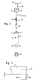
- Fig. 1
- eine perspektivische Explosionsdarstellung eines elektrischen Verbinders nach einer bevorzugten Ausführungsform der Erfindung,
- Fig. 2
- eine Explosionsdarstellung eines Prüfelements in dem elektrischen Verbinder in Fig. 1,
- Fig. 3
- eine schematische Draufsicht auf ein Gehäuseoberteil des elektrischen Verbinders in Fig. 1 im Bereich der Öffnung für das Verriegelungselement,
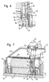
- Fig. 4
- eine schematische, perspektivische Schnittansicht des elektrischen Verbinders in Fig. 1 in einer Anfangsstellung mit nur teilweise zusammengesteckten Verbinderteilen entlang der in Fig. 3 gezeigten gestrichelten Linien, wobei die Geräteaufnahme und das Flachkontaktgehäuse entlang der Linie B-B und die Gehäusekappe entlang der Linie A-A geschnitten sind.
- Fig. 5
- eine schematische Schnittansicht des elektrischen Verbinders in Fig. 4, bei dem die Betätigungseinrichtung sich in unverriegelter Endstellung befindet,
- Fig. 6
- einen vergrößerten Ausschnitt des elektrischen Verbinders in Fig. 5 im Bereich der Prüfkontaktelemente,
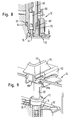
- Fig. 7
- den elektrischen Verbinder in Fig. 4 in einer Position, in der die Betätigungseinrichtung sich in Endstellung befindet und nur teilweise verriegelt ist,
- Fig. 8
- einen vergrößerten Ausschnitt aus der Ansicht des elektrischen Verbinders in Fig. 7 im Bereich der Prüfkontaktelemente, und
- Fig. 9
- eine schematische perspektivische Ansicht eines Teils des in den vorherigen Figuren dargestellten elektrischen Verbinders, wobei der Bereich der Verriegelungseinrichtung bei verriegelter Betätigungseinrichtung in Endstellung dargestellt ist.
- 10
- Geräteaufnahme
- 12
- Flachkontaktgehäuse
- 14
- Gehäusekappe
- 16
- Kammer
- 18
- Prüfelement
- 20
- Betätigungseinrichtung
- 22
- Kontaktelemente
- 24
- erstes Prüfkontaktelement
- 26a, 26b
- Führungsflächen
- 28
- Zapfen
- 30
- Kontaktelementkammern
- 32a, 32b
- Führungsschlitze
- 34
- Schulter
- 36
- Haken
- 38
- geschlossener Kappenteil
- 40
- Wände
- 42
- Verriegelungsöffnung
- 44
- Hebel
- 46a, 46b
- U-Schenkel
- 47
- Zapfen
- 48a, 48b
- Langlöcher
- 50
- Schlitz
- 52
- U-Steg
- 54
- Verriegelungselement
- 56
- Führungsprofile
- 58
- Rampe
- 60
- Haltefläche
- 62
- Hülse
- 64
- Anschlußelement
- 66
- Druckstück
- 68
- Kompressionsdichtung
- 70
- zurückgesetzter Abschnitt
- 72
- Rastelemente
- 74
- Rastvorsprünge
- 76
- Fläche
- 78
- weitere Haltefläche
- 80
- zweites Prüfkontaktelement
- 82
- Leitung
- 84
- Radialdichtungen
- 86
- Nase
- 88a, 88b
- Nasen
- 90a, 90b
- Ränder
- 92
- Schulter
- 94
- Schulter
Claims (17)
- Elektrischer Verbinder für Kraftfahrzeuge mitwobei die Prüfeinrichtungzumindest einem ersten und einem zweiten, jeweils mit Kontaktelementen (22) versehenen Verbinderteil (10, 12),einer Betätigungseinrichtung (20), die zwischen einer Ausgangsstellung und einer Endstellung verstellbar ist und deren Verstellbewegung eine Relativbewegung des ersten und des zweiten Verbinderteils (10, 12) bewirkt, um das erste und das zweite Verbinderteil (10, 12) zusammenzustecken und elektrische Verbindungen zwischen den Kontaktelementen (22) durch Bewegung der Betätigungseinrichtung (20) in die Endstellung herzustellen,einer Verriegelungseinrichtung (42, 54) zur Verriegelung der Betätigungseinrichtung (20) in der Endstellung undeiner elektromechanischen Prüfeinrichtung (16, 18, 24) zur Prüfung, ob die Betätigungseinrichtung (20) die verriegelte Endstellung erreicht hat oder nicht,
ein erstes Prüfkontaktelement (24) an dem ersten Verbinderteil (10), eine Kammer (16) in dem zweiten Verbinderteil (12) sowie wenigstens ein Prüfelement (18) mit einem zweiten Prüfkontaktelement (80) umfaßt, wobei die Kammer (16) derart ausgebildet und zumindest in der Endstellung der Betätigungseinrichtung (20) das Prüfelement (18) in der Kammer (16) derart beweglich gelagert ist, daß das Prüfelement (18) beim Verriegeln der Betätigungseinrichtung (20) in der Endstellung durch Herstellen einer elektrischen Verbindung zwischen dem ersten und dem zweiten Prüfkontaktelement (24, 80) einen Signalweg bereitstellt, der bei nicht erreichter verriegelter Endstellung unterbrochen ist und
wobei mindestens eine Dichtung (68) vorgesehen ist, die so ausgebildet ist, daß bei erreichter verriegelter Endstellung das erste und das zweite Prüfkontaktelement (24, 80) in ihrem Kontaktbereich gegen in die Kammer (16) aus Richtung des zweiten Verbinderteils (12) eindringende Fremdstoffe, insbesondere Feuchtigkeit, abgedichtet sind. - Elektrischer Verbinder nach Anspruch 1,
dadurch gekennzeichnet, daß das Prüfelement (18) durch Bewegung eines Verriegelungselements (54) der Verriegelungseinrichtung (42, 54) bewegbar ist, wenn sich die Betätigungseinrichtung (20) in der Endstellung befindet. - Elektrischer Verbinder nach Anspruch 1 oder 2,
dadurch gekennzeichnet, daß die Dichtung (68) an dem Prüfelement (18) gehalten ist. - Elektrischer Verbinder nach einem der vorhergehenden Ansprüche,
dadurch gekennzeichnet, daß ein elastisch verformbares, bei verriegelter Betätigungseinrichtung (20) vorgespanntes und mit dem Prüfelement (18) gekoppeltes Element (68) vorgesehen ist, das so ausgebildet ist, daß bei Lösen der Verriegelungseinrichtung (42, 54) das Prüfelement (18) mit dem zweiten Prüfkontaktelement (80) unter Unterbrechung des Signalwegs von dem ersten Prüfkontaktelement (24) wegbewegt wird. - Elektrischer Verbinder nach Anspruch 4,
dadurch gekennzeichnet, daß als elastisch verformbares Element die insbesondere als Kompressionsdichtung ausgebildete Dichtung (68) vorgesehen ist, wobei bevorzugt die Dichtung durch Relativbewegung des Prüfelements (18) und der Kammer (16) komprimierbar und so ausgebildet und angeordnet ist, daß zumindest bei Erreichen der verriegelten Endstellung der Betätigungseinrichtung (20) ein Spalt zwischen Prüfelement (18) und Wand der Kammer (16) abgedichtet ist. - Elektrischer Verbinder nach Anspruch 5,
dadurch gekennzeichnet, daß die Prüfeinrichtung so ausgebildet ist, daß die Dichtung (68) zumindest bei Erreichen der verriegelten Endstellung der Betätigungseinrichtung (20) zwischen einem Vorsprung (92) am Prüfelement (18) und einem entsprechenden Vorsprung (94) an der Wand der Kammer, an deren Boden oder an dem ersten Verbinderteil (10) komprimiert wird. - Elektrischer Verbinder nach Anspruch 6,
dadurch gekennzeichnet, daß die Dichtung (68) hülsenartig ausgebildet ist und das Prüfelement (18) umgibt. - Elektrischer Verbinder nach einem der vorhergehenden Ansprüche,
dadurch gekennzeichnet, daß das Prüfelement (18) in dem die Kammer (16) enthaltenden Verbinderteil (12) und bevorzugt in der Kammer (16) so zwangsgeführt ist, daß das Prüfelement (18) entlang der Kammer (16) begrenzt bewegbar ist. - Elektrischer Verbinder nach einem der vorhergehenden Ansprüche,
dadurch gekennzeichnet, daß das Prüfelement (18) eine Hülse (62), ein darin angeordnetes Anschlußelement (64) mit dem zweiten Prüfkontaktelement (80) und einer Leitung (82) sowie ein Druckstück (66) aufweist, das mit der Hülse (62) an einem Ende verbunden und zur Betätigung durch die Verriegelungseinrichtung (42, 54) ausgebildet ist. - Elektrischer Verbinder nach Anspruch 9,
dadurch gekennzeichnet, daß das Anschlußelement (64) insbesondere im Bereich seines vom zweiten Prüfkontaktelement (80) abgewandten Endes mindestens eine Dichtung (84) zur Abdichtung des Zwischenraums zwischen Anschlußelement (64) und Hülse (62) aufweist. - Elektrischer Verbinder nach einem der vorhergehenden Ansprüche,
dadurch gekennzeichnet, daß ein Verriegelungselement (54) der Verriegelungseinrichtung in einer Richtung im wesentlichen senkrecht zur Bewegungsrichtung des Prüfelements (18) aus einer unverriegelten in eine verriegelte Stellung verschiebbar ist. - Elektrischer Verbinder nach Anspruch 11,
dadurch gekennzeichnet, daß das Prüfelement (18) an seinem mit dem Verriegelungselement (54) zusammenwirkenden Ende eine zur Steckrichtung geneigte Fläche (76) aufweist, und die Verriegelungseinrichtung so ausgebildet ist, daß ein, insbesondere eine entsprechend der Fläche (76) des Prüfelements (18) geneigte Fläche oder Rampe umfassender, Bereich (58) des Verriegelungselements (54) bei Verschiebung an der Fläche (76) des Prüfelements (18) angreift. - Elektrischer Verbinder nach einem der vorhergehenden Ansprüche,
dadurch gekennzeichnet, daß ein Verriegelungselement (54) der Verriegelungseinrichtung an der Betätigungseinrichtung (20) gehalten ist. - Elektrischer Verbinder nach einem der vorhergehenden Ansprüche,
dadurch gekennzeichnet, daß ein Gehäuseteil (14) mit einer Verriegelungsöffnung (42) vorgesehen ist, das so ausgebildet ist, daß bei Bewegung der Betätigungseinrichtung (20) in die Endstellung ein Verriegelungselement (54) der Verriegelungseinrichtung in die Verriegelungsöffnung (42) eingeführt wird und durch Verschiebung darin verriegelbar ist, wobei bevorzugt mindestens ein entsprechender Vorsprung (88a, 88b) des Verriegelungselements (54) hinter die Ränder der Verriegelungsöffnung (42) greift. - Elektrischer Verbinder nach einem der vorhergehenden Ansprüche,
dadurch gekennzeichnet, daß das eine Verbinderteil (12) als insbesondere in Form eines Flachkontaktgehäuses vorgesehenes Steckteil (12) und das andere Verbinderteil (10) als insbesondere in Form einer Geräteaufnahme vorgesehenes Aufnahmeteil (10) für das Steckteil (12) ausgebildet ist, wobei das Steckteil (12) mittels der Betätigungseinrichtung (20) zumindest teilweise auf das Aufnahmeteil (10) zu bewegbar ist. - Elektrischer Verbinder nach einem der vorhergehenden Ansprüche,
dadurch gekennzeichnet, daß die Betätigungseinrichtung (20) einen an dem einen Verbinderteil (12) schwenkbar gelagerten Hebel (44) umfaßt, der zur Umsetzung seiner Schwenkbewegung in die Relativbewegung der Verbinderteile (10, 12) über eine Kulissenführung, die bevorzugt eine Stift-Langloch-Anordnung (28, 48a, 48b) umfaßt, mit dem anderen Verbinderteil (10) zusammenwirkt. - Elektrischer Verbinder nach Anspruch 16,
dadurch gekennzeichnet, daß der Hebel (44) U-förmig ausgebildet und über die U-Schenkel (46a, 46b) mit den Verbinderteilen (10, 12) gekoppelt ist, wobei ein Verriegelungselement (54) der Verriegelungseinrichtung (42, 54) an dem die U-Schenkel (46a, 46b) verbindenden U-Steg (52), der vorzugsweise in der Endstellung auf dem einen Verbinderteil (12) aufliegt, beweglich gehalten ist.
Applications Claiming Priority (2)
| Application Number | Priority Date | Filing Date | Title |
|---|---|---|---|
| DE10131191 | 2001-06-28 | ||
| DE2001131191 DE10131191A1 (de) | 2001-06-28 | 2001-06-28 | Elektrischer Verbinder |
Publications (2)
| Publication Number | Publication Date |
|---|---|
| EP1271708A2 true EP1271708A2 (de) | 2003-01-02 |
| EP1271708A3 EP1271708A3 (de) | 2003-08-13 |
Family
ID=7689768
Family Applications (1)
| Application Number | Title | Priority Date | Filing Date |
|---|---|---|---|
| EP02014111A Withdrawn EP1271708A3 (de) | 2001-06-28 | 2002-06-24 | Elektrischer Verbinder |
Country Status (2)
| Country | Link |
|---|---|
| EP (1) | EP1271708A3 (de) |
| DE (1) | DE10131191A1 (de) |
Cited By (4)
| Publication number | Priority date | Publication date | Assignee | Title |
|---|---|---|---|---|
| WO2006023673A1 (en) * | 2004-08-20 | 2006-03-02 | Molex Incorporated | Lever type electrical connector |
| EP1715551A2 (de) | 2005-04-22 | 2006-10-25 | Sumitomo Wiring Systems, Ltd. | Verbinder und Montageverfahren |
| WO2006119000A1 (en) * | 2005-04-29 | 2006-11-09 | Tyco Electronics Corporation | Duplex plug adapter module |
| US7329137B2 (en) | 2005-10-05 | 2008-02-12 | Tyco Electronics Corporation | Modular plug with slider latch |
Family Cites Families (10)
| Publication number | Priority date | Publication date | Assignee | Title |
|---|---|---|---|---|
| US3912889A (en) * | 1974-02-14 | 1975-10-14 | Bendix Corp | Electrical connector having an internal switch |
| US5078615A (en) * | 1989-05-09 | 1992-01-07 | Physio-Control Corporation | Connector for use with medical instruments |
| US5135410A (en) * | 1990-05-30 | 1992-08-04 | Sumitomo Wiring Systems, Ltd. | Electric connector assembly |
| DE9216667U1 (de) * | 1992-12-07 | 1993-05-06 | Siemens AG, 8000 München | Steckverbinder |
| US5458496A (en) * | 1993-07-12 | 1995-10-17 | Sumitomo Wiring Systems, Ltd. | Charge coupling for electric vehicle |
| JP3433432B2 (ja) * | 1993-12-28 | 2003-08-04 | 矢崎総業株式会社 | 給電コネクタ |
| JPH1174023A (ja) * | 1997-08-29 | 1999-03-16 | Yazaki Corp | レバー嵌合式コネクタの嵌合検知構造 |
| US5938458A (en) * | 1998-06-17 | 1999-08-17 | Molex Incorporated | Lever type electrical connector |
| DE19905507C2 (de) * | 1999-02-10 | 2001-04-12 | Tyco Electronics Logistics Ag | Leiterplatten-Nullkraftsteckverbinder |
| US6139351A (en) * | 1999-06-16 | 2000-10-31 | Delphi Technologies, Inc. | High power connection system |
-
2001
- 2001-06-28 DE DE2001131191 patent/DE10131191A1/de not_active Withdrawn
-
2002
- 2002-06-24 EP EP02014111A patent/EP1271708A3/de not_active Withdrawn
Cited By (9)
| Publication number | Priority date | Publication date | Assignee | Title |
|---|---|---|---|---|
| WO2006023673A1 (en) * | 2004-08-20 | 2006-03-02 | Molex Incorporated | Lever type electrical connector |
| KR100905837B1 (ko) * | 2004-08-20 | 2009-07-02 | 몰렉스 인코포레이티드 | 레버형 전기 커넥터 |
| CN100514763C (zh) * | 2004-08-20 | 2009-07-15 | 莫莱克斯公司 | 杠杆式电连接件 |
| EP1715551A2 (de) | 2005-04-22 | 2006-10-25 | Sumitomo Wiring Systems, Ltd. | Verbinder und Montageverfahren |
| EP1715551A3 (de) * | 2005-04-22 | 2008-12-03 | Sumitomo Wiring Systems, Ltd. | Verbinder und Montageverfahren |
| WO2006119000A1 (en) * | 2005-04-29 | 2006-11-09 | Tyco Electronics Corporation | Duplex plug adapter module |
| US7311539B2 (en) | 2005-04-29 | 2007-12-25 | Tyco Electronics Corporation | Duplex plug adapter module |
| CN100514103C (zh) * | 2005-04-29 | 2009-07-15 | 泰科电子公司 | 双工插头适配器模块 |
| US7329137B2 (en) | 2005-10-05 | 2008-02-12 | Tyco Electronics Corporation | Modular plug with slider latch |
Also Published As
| Publication number | Publication date |
|---|---|
| EP1271708A3 (de) | 2003-08-13 |
| DE10131191A1 (de) | 2003-01-09 |
Similar Documents
| Publication | Publication Date | Title |
|---|---|---|
| DE69600063T2 (de) | Verbinder mit Sekundärverriegelung und Kupplungsvorrichtung | |
| DE69504217T2 (de) | Elektrischer Verbinder mit Lagesicherungsvorrichtung | |
| DE60104612T2 (de) | Steckverbinder | |
| EP3937313B1 (de) | Elektrischer steckverbinder | |
| DE19654294C2 (de) | Steckerbindungssystem zur Verhinderung einer unvollständigen Verbindung | |
| DE102012209298B4 (de) | Elektrischer Steckverbinder, Steckverbinderanordnung sowie Verfahren zum Montieren des Steckverbinders | |
| EP2209169B1 (de) | Elektrisches Gerät | |
| DE4408985B4 (de) | Elektrische Einrichtung, insbesondere Reihenklemme, mit einer Klemme für eine Schnellverbindung | |
| EP3679632B1 (de) | Steckverbinder mit sekundärriegel zur festlegung von kontaktpartnern in seinem kontaktträger | |
| DE102014112258A1 (de) | Clipsystem | |
| DE19530334A1 (de) | Steckeranordnung mit einem Betätigungsschieber | |
| DE69900798T2 (de) | Kupplung mit selbsttätiger Verbindung und Trennung | |
| DE102017119643A1 (de) | Komplett abgedichteter Steckverbinder mit verbesserten Haltekräften | |
| WO2020083886A1 (de) | Elektrischer Stecker, elektrisches Gerät, elektrische Steckverbindung und Verfahren zur Herstellung eines elektrischen Geräts | |
| WO2012084541A1 (de) | Anschlussvorrichtung mit federklemme | |
| EP1271708A2 (de) | Elektrischer Verbinder | |
| EP1430567A1 (de) | Elektrische steckvorrichtung | |
| DE102016217456B3 (de) | Anordnung für einen elektrischen Steckverbinder sowie Steckverbinder mit einem Kontaktgehäuse, Umgehäuse und Sicherungselement | |
| WO2022218466A1 (de) | Klemmfederkontakteinrichtung mit überdehnschutz und steckverbindereinsatz mit mindestens einer solchen klemmfederkontakteinrichtung | |
| DE202004000419U1 (de) | Schraubenlose Leiteranschlussklemme | |
| EP0703641A2 (de) | Elektrisches Steckverbindungsteil | |
| DE19949386C2 (de) | Geräte-Anschlusskasten mit Schneidtechnik | |
| EP2681805A1 (de) | System von auf montageschienen fixierten steckverbindern | |
| DE10326834B4 (de) | Steckverbinder | |
| DE19613051C1 (de) | Elektrisches Steckverbindungsteil |
Legal Events
| Date | Code | Title | Description |
|---|---|---|---|
| PUAI | Public reference made under article 153(3) epc to a published international application that has entered the european phase |
Free format text: ORIGINAL CODE: 0009012 |
|
| AK | Designated contracting states |
Kind code of ref document: A2 Designated state(s): AT BE CH CY DE DK ES FI FR GB GR IE IT LI LU MC NL PT SE TR |
|
| AX | Request for extension of the european patent |
Free format text: AL;LT;LV;MK;RO;SI |
|
| PUAL | Search report despatched |
Free format text: ORIGINAL CODE: 0009013 |
|
| AK | Designated contracting states |
Designated state(s): AT BE CH CY DE DK ES FI FR GB GR IE IT LI LU MC NL PT SE TR |
|
| AX | Request for extension of the european patent |
Extension state: AL LT LV MK RO SI |
|
| 17P | Request for examination filed |
Effective date: 20030905 |
|
| AKX | Designation fees paid |
Designated state(s): DE FR IT |
|
| GRAP | Despatch of communication of intention to grant a patent |
Free format text: ORIGINAL CODE: EPIDOSNIGR1 |
|
| STAA | Information on the status of an ep patent application or granted ep patent |
Free format text: STATUS: THE APPLICATION IS DEEMED TO BE WITHDRAWN |
|
| 18D | Application deemed to be withdrawn |
Effective date: 20061025 |