EP1271744A2 - Startersatz - Google Patents
Startersatz Download PDFInfo
- Publication number
- EP1271744A2 EP1271744A2 EP02394075A EP02394075A EP1271744A2 EP 1271744 A2 EP1271744 A2 EP 1271744A2 EP 02394075 A EP02394075 A EP 02394075A EP 02394075 A EP02394075 A EP 02394075A EP 1271744 A2 EP1271744 A2 EP 1271744A2
- Authority
- EP
- European Patent Office
- Prior art keywords
- pack
- battery
- housing
- handle
- switch
- Prior art date
- Legal status (The legal status is an assumption and is not a legal conclusion. Google has not performed a legal analysis and makes no representation as to the accuracy of the status listed.)
- Withdrawn
Links
Images




Classifications
-
- F—MECHANICAL ENGINEERING; LIGHTING; HEATING; WEAPONS; BLASTING
- F02—COMBUSTION ENGINES; HOT-GAS OR COMBUSTION-PRODUCT ENGINE PLANTS
- F02N—STARTING OF COMBUSTION ENGINES; STARTING AIDS FOR SUCH ENGINES, NOT OTHERWISE PROVIDED FOR
- F02N11/00—Starting of engines by means of electric motors
- F02N11/14—Starting of engines by means of electric starters with external current supply
-
- H—ELECTRICITY
- H02—GENERATION; CONVERSION OR DISTRIBUTION OF ELECTRIC POWER
- H02J—ELECTRIC POWER NETWORKS; CIRCUIT ARRANGEMENTS OR SYSTEMS FOR SUPPLYING OR DISTRIBUTING ELECTRIC POWER; SYSTEMS FOR STORING ELECTRIC ENERGY
- H02J1/00—Circuit arrangements for DC mains or DC distribution networks
- H02J1/10—Parallel operation of DC sources
- H02J1/122—Provisions for temporary connection of DC sources of essentially the same voltage, e.g. jumpstart cables
-
- H—ELECTRICITY
- H02—GENERATION; CONVERSION OR DISTRIBUTION OF ELECTRIC POWER
- H02J—ELECTRIC POWER NETWORKS; CIRCUIT ARRANGEMENTS OR SYSTEMS FOR SUPPLYING OR DISTRIBUTING ELECTRIC POWER; SYSTEMS FOR STORING ELECTRIC ENERGY
- H02J7/00—Circuit arrangements for charging or discharging batteries or for supplying loads from batteries
- H02J7/70—Circuit arrangements for charging or discharging batteries or for supplying loads from batteries characterised by the mechanical construction
- H02J7/751—Circuit arrangements for charging or discharging batteries or for supplying loads from batteries characterised by the mechanical construction concerning the insertion or the connection of the batteries
Definitions
- the invention relates to a portable engine starter pack which is used for over-riding malfunctioning or discharged batteries to start engines or the like.
- a portable engine starter pack comprising a housing; a battery located in the housing, the battery having a positive terminal and a negative terminal; a socket having a positive socket portion connected to the positive terminal of the battery, and a negative socket portion connected to the negative terminal of the battery; the pack having at least two different supply voltages; a switch for switching between the supply voltages; and means for inhibiting connection to an incorrect voltage.
- the means for inhibiting connection to an incorrect voltage comprises the switch.
- the switch has an operating handle which is movable between at least two different supply voltage positions.
- the handle is movable between an off position and at least two different supply voltage positions.
- the operating handle requires different movements in configurations for different voltage settings. In one case the operating handle requires at least a two step movement to move to one of the supply voltage settings. A push or pull movement may be followed by a rotational movement.
- the pack comprises an indicating means.
- the indicating means is a battery condition indicator.
- the pack comprises a warning indicator for indicating if a user has incorrectly connected to a battery to be charged.
- the indicator is a visual and/or an audible alarm.
- the pack includes a charging socket for charging the battery in the housing.
- the starter pack comprises a trip switch to prevent connection to an incorrect voltage during charging.
- the trip switch preferably comprises a fuse for electrically protecting a charging system.
- the housing comprises a base, a top, a rear wall, a front wall and a pair of sides.
- an operating handle of the switch extends from the front wall or rear wall of the housing and the housing has forwardly and/or rearwardly extending projections which extend proud of the panel carrying the handle to substantially protect the handle against damage if the housing is tipped into a position in which the panel carrying the handle is lowermost.
- the sides are extended to define the forward and/or rearward projections.
- the housing comprises a carrying handle.
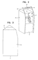
- the starter pack has a metallic housing 1 comprising a base 2, a top 3, a rear 4, a front panel 5 and a pair of sides 6, 7.
- the sides 6, 7 extend upwardly above the top 3 to define brackets 8, 9 between which a carrying handle 10 is mounted.
- a battery (not shown) having a positive and a negative terminal is located in the housing.
- a socket 20 extends from the housing for connection to leads 21 with crocodile clips 22 for connection to the terminals of a battery.
- the socket 20 has a positive socket portion connected to the positive terminal of the battery in the housing and a negative socket portion connected to the negative terminal of the battery.
- a switch operated by a handle 25 is mounted on the front panel 5 for movement between an off position and two different voltage supply positions such as 12 volt and 24 volt supply.
- the front panel 5 also has test buttons 26 and a battery condition indicator 27. In this case the front panel 5 also carries a re-charging socket 28 for connection to a mains supply after the starter pack has been used.
- the sides 6, 7 extend below the level of the base 2 to define support feet 12.
- the sides 6, 7 also extend both forwardly and rearwardly proud of the panels of the front 5 and the rear 4 of the housing to define an area which substantially protects the various switches, handles and indicators 25, 26, 27, 28 carried by the first panel 5 if the pack is toppled over with the front panel 5 lowermost as illustrated in Fig. 8 . In this way these elements are protected against damage and an extremely robust starter pack is thereby provided.
- front panel 5 is recessed and angled rearwardly to allow easy viewing and operation of the unit.
- the starter pack includes two thermal trip fuses to protect the internal wiring from damage should the handle 25 be turned to the incorrect voltage position.
- the unit also includes visual and/or audible alerting means in the form of an alarm buzzer if a user incorrectly connects the crocodile clips 22.
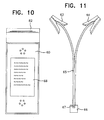
- a starter pack according to the invention together with an ancillary charging system (Fig. 12) and user battery connection system (Fig. 11).
- the unit incorporates a switching system to avoid accidental switching of the unit into a 24 volt setting while it is connected to equipment not designed to take 24 volt current and thus damaging the equipment.
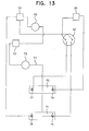
- the numerals represent the following components.
- a switching mechanism is used whereby the switch handle 83 must be pulled out towards the operator before being turned clockwise to the 24 volt setting, thus avoiding accidental turning of the switch handle directly into the 24 volt setting.
- the switch handle 83 is turned anti-clockwise back to the off setting.
- the switch handle 83 is turned anti-clockwise from the off setting to the 12 volt setting.
- This system protects the user from making an error and also prevents the user from damaging the unit or the equipment being energised.
- the charging plug 62 is wired so as to charge both 12 volt batteries individually and at the same time. This is a 12-24 volt system, if the transfer switch 54 is turned to the 24 volt position during the charging process it would result in damage to the unit's internal wiring and the charger. To avoid such damage thermal trip fuses 52 and 55 are provided.
- the wiring circuit is arranged so that if the unit is being charged by means of the charging plug 62 in conjunction with a 12 volt charger 61 and the operator ignores the warning instructions and still pulls and turns the transfer switch 54 by means of the switch handle 83 clockwise into the 24 volt setting thus causing a direct short across the loops in the charging plug 62, both thermal trip fuses 52 and 55 trip immediately, thus protecting both the internal charging circuitry and the charging system.
- the transfer switch 83 When the transfer switch 83 is moved to the 24 volt setting it connects negative battery pole 77 with positive battery pole 76 thus aligning the batteries in series giving 24 volts dc at snap connector 58. If the transfer switch 54 is in the 24 volt setting and the charging plug 62 is plugged into the unit the loops in the charging plug 62 will cause direct shorts across the positive charging wire coming from battery pole 76 and the negative charging wire 77 causing both thermal trip fuses 52 and 55 to trip out due to the internal loops linking the poles in charging plug 62.
Landscapes
- Engineering & Computer Science (AREA)
- Power Engineering (AREA)
- Chemical & Material Sciences (AREA)
- Combustion & Propulsion (AREA)
- Mechanical Engineering (AREA)
- General Engineering & Computer Science (AREA)
- Charge And Discharge Circuits For Batteries Or The Like (AREA)
- Battery Mounting, Suspending (AREA)
Applications Claiming Priority (2)
| Application Number | Priority Date | Filing Date | Title |
|---|---|---|---|
| IE20010577 | 2001-06-21 | ||
| IE20010577 | 2001-06-21 |
Publications (2)
| Publication Number | Publication Date |
|---|---|
| EP1271744A2 true EP1271744A2 (de) | 2003-01-02 |
| EP1271744A3 EP1271744A3 (de) | 2005-01-05 |
Family
ID=11042798
Family Applications (1)
| Application Number | Title | Priority Date | Filing Date |
|---|---|---|---|
| EP02394075A Withdrawn EP1271744A3 (de) | 2001-06-21 | 2002-06-21 | Startersatz |
Country Status (1)
| Country | Link |
|---|---|
| EP (1) | EP1271744A3 (de) |
Cited By (4)
| Publication number | Priority date | Publication date | Assignee | Title |
|---|---|---|---|---|
| EP1642373A4 (de) * | 2003-03-21 | 2006-08-16 | Vector Prod Inc | Kombiniertes starthilfe- und hochfrequenzladegerät |
| WO2019060135A1 (en) | 2017-09-22 | 2019-03-28 | The Noco Company | RECHARGEABLE BATTERY BACKUP DEVICE HAVING CONTROLLER SWITCHING BACKLIGHT SYSTEM |
| CN117751237A (zh) * | 2021-05-21 | 2024-03-22 | 德特兰营运美国股份有限公司 | 具有经由单个输出插孔的自动操作模式的电池充电器和发动机跨接启动系统 |
| WO2025194406A1 (zh) * | 2024-03-21 | 2025-09-25 | 戴健郎 | 救援电池 |
Family Cites Families (4)
| Publication number | Priority date | Publication date | Assignee | Title |
|---|---|---|---|---|
| US4184580A (en) * | 1977-06-15 | 1980-01-22 | Ellis Austin J Jr | Coin operated battery charger and charging system check |
| US4667141A (en) * | 1985-05-17 | 1987-05-19 | Helen H. Smith Steele | Coin or token operated portable car starter |
| US5083076A (en) * | 1989-11-13 | 1992-01-21 | P.S.O. Electric, Incorporated | Portable battery booster |
| US5982138A (en) * | 1998-12-17 | 1999-11-09 | Vector Manufacturing, Ltd. | Portable electrical energy source |
-
2002
- 2002-06-21 EP EP02394075A patent/EP1271744A3/de not_active Withdrawn
Cited By (13)
| Publication number | Priority date | Publication date | Assignee | Title |
|---|---|---|---|---|
| EP1642373A4 (de) * | 2003-03-21 | 2006-08-16 | Vector Prod Inc | Kombiniertes starthilfe- und hochfrequenzladegerät |
| JP2022081473A (ja) * | 2017-09-22 | 2022-05-31 | ザ・ノコ・カンパニー | 制御スイッチバックライトシステムを備えた充電式バッテリジャンプスタート装置 |
| EP3656037A4 (de) * | 2017-09-22 | 2020-08-05 | The Noco Company | Starthilfevorrichtung für wiederaufladbare batterien mit steuerschalterhintergrundbeleuchtungssystem |
| JP2020534463A (ja) * | 2017-09-22 | 2020-11-26 | ザ・ノコ・カンパニーThe Noco Company | 制御スイッチバックライトシステムを備えた充電式バッテリジャンプスタート装置 |
| AU2018336995B2 (en) * | 2017-09-22 | 2021-09-09 | The Noco Company | Rechargeable battery jump starting device with control switch backlight system |
| EP3944458A1 (de) * | 2017-09-22 | 2022-01-26 | The Noco Company | Starthilfevorrichtung für wiederaufladbare batterien mit ladesystem für abwechselndes laden |
| WO2019060135A1 (en) | 2017-09-22 | 2019-03-28 | The Noco Company | RECHARGEABLE BATTERY BACKUP DEVICE HAVING CONTROLLER SWITCHING BACKLIGHT SYSTEM |
| EP4060848A1 (de) * | 2017-09-22 | 2022-09-21 | The Noco Company | Starthilfevorrichtung mit elektrischem steuerschalterhintergrundbeleuchtungssystem |
| GB2583178B (en) * | 2017-09-22 | 2022-10-05 | Noco Co | Rechargeable battery jump starting device with control switch backlight system |
| US11557906B2 (en) | 2017-09-22 | 2023-01-17 | The Noco Company | Rechargeable battery jump starting device with control switch backlight system |
| JP7762084B2 (ja) | 2017-09-22 | 2025-10-29 | ザ・ノコ・カンパニー | 制御スイッチバックライトシステムを備えた充電式バッテリジャンプスタート装置 |
| CN117751237A (zh) * | 2021-05-21 | 2024-03-22 | 德特兰营运美国股份有限公司 | 具有经由单个输出插孔的自动操作模式的电池充电器和发动机跨接启动系统 |
| WO2025194406A1 (zh) * | 2024-03-21 | 2025-09-25 | 戴健郎 | 救援电池 |
Also Published As
| Publication number | Publication date |
|---|---|
| EP1271744A3 (de) | 2005-01-05 |
Similar Documents
| Publication | Publication Date | Title |
|---|---|---|
| US6400121B1 (en) | Starter pack | |
| JP7523422B2 (ja) | 消耗バッテリ又は放電バッテリ事前調整システムを備えた充電式バッテリジャンプスタート装置 | |
| AU2023251401B2 (en) | Rechargeable battery jump starting device with battery detection system | |
| US20250042278A1 (en) | Jump Starting Apparatus | |
| US6212054B1 (en) | Spark proof booster cable system | |
| US7148580B2 (en) | Method of and system for starting engine-driven power equipment | |
| CN102132468B (zh) | 电动车充电线组 | |
| KR20190009292A (ko) | 시각적 표시기 부(part)를 포함하는 차량 충전 커넥터 | |
| US4831321A (en) | Trickle jumping charging device | |
| IE20020510A1 (en) | A starter pack | |
| US20050280979A1 (en) | Power source cabinet | |
| IE83951B1 (en) | A battery starter pack | |
| KR100840917B1 (ko) | 충전기 | |
| US6177778B1 (en) | Battery adapter capable of receiving power from at least two power sources and of being in a docking station, and a battery arrangement including a battery charger and a docking station | |
| JPH11233159A (ja) | 充電式電池パック | |
| JPH08124546A (ja) | 充電池パック |
Legal Events
| Date | Code | Title | Description |
|---|---|---|---|
| PUAI | Public reference made under article 153(3) epc to a published international application that has entered the european phase |
Free format text: ORIGINAL CODE: 0009012 |
|
| AK | Designated contracting states |
Kind code of ref document: A2 Designated state(s): AT BE CH CY DE DK ES FI FR GB GR IE IT LI LU MC NL PT SE TR |
|
| AX | Request for extension of the european patent |
Free format text: AL;LT;LV;MK;RO;SI |
|
| 17P | Request for examination filed |
Effective date: 20040910 |
|
| PUAL | Search report despatched |
Free format text: ORIGINAL CODE: 0009013 |
|
| AK | Designated contracting states |
Kind code of ref document: A3 Designated state(s): AT BE CH CY DE DK ES FI FR GB GR IE IT LI LU MC NL PT SE TR |
|
| AX | Request for extension of the european patent |
Extension state: AL LT LV MK RO SI |
|
| 17Q | First examination report despatched |
Effective date: 20050221 |
|
| AKX | Designation fees paid |
Designated state(s): AT BE CH CY DE DK ES FI FR GB GR IE IT LI LU MC NL PT SE TR |
|
| STAA | Information on the status of an ep patent application or granted ep patent |
Free format text: STATUS: THE APPLICATION IS DEEMED TO BE WITHDRAWN |
|
| 18D | Application deemed to be withdrawn |
Effective date: 20050906 |