EP1272002A2 - Mikrofonanordnung in einem hinter dem Ohr tragbaren Hörgerät - Google Patents
Mikrofonanordnung in einem hinter dem Ohr tragbaren Hörgerät Download PDFInfo
- Publication number
- EP1272002A2 EP1272002A2 EP02013819A EP02013819A EP1272002A2 EP 1272002 A2 EP1272002 A2 EP 1272002A2 EP 02013819 A EP02013819 A EP 02013819A EP 02013819 A EP02013819 A EP 02013819A EP 1272002 A2 EP1272002 A2 EP 1272002A2
- Authority
- EP
- European Patent Office
- Prior art keywords
- microphone
- hearing aid
- sound
- housing
- sound inlet
- Prior art date
- Legal status (The legal status is an assumption and is not a legal conclusion. Google has not performed a legal analysis and makes no representation as to the accuracy of the status listed.)
- Granted
Links
Images

Classifications
-
- H—ELECTRICITY
- H04—ELECTRIC COMMUNICATION TECHNIQUE
- H04R—LOUDSPEAKERS, MICROPHONES, GRAMOPHONE PICK-UPS OR LIKE ACOUSTIC ELECTROMECHANICAL TRANSDUCERS; ELECTRIC HEARING AIDS; PUBLIC ADDRESS SYSTEMS
- H04R25/00—Electric hearing aids
- H04R25/40—Arrangements for obtaining a desired directivity characteristic
- H04R25/402—Arrangements for obtaining a desired directivity characteristic using contructional means
-
- H—ELECTRICITY
- H04—ELECTRIC COMMUNICATION TECHNIQUE
- H04R—LOUDSPEAKERS, MICROPHONES, GRAMOPHONE PICK-UPS OR LIKE ACOUSTIC ELECTROMECHANICAL TRANSDUCERS; ELECTRIC HEARING AIDS; PUBLIC ADDRESS SYSTEMS
- H04R1/00—Details of transducers, loudspeakers or microphones
- H04R1/20—Arrangements for obtaining desired frequency or directional characteristics
- H04R1/32—Arrangements for obtaining desired frequency or directional characteristics for obtaining desired directional characteristic only
- H04R1/34—Arrangements for obtaining desired frequency or directional characteristics for obtaining desired directional characteristic only by using a single transducer with sound reflecting, diffracting, directing or guiding means
- H04R1/342—Arrangements for obtaining desired frequency or directional characteristics for obtaining desired directional characteristic only by using a single transducer with sound reflecting, diffracting, directing or guiding means for microphones
-
- H—ELECTRICITY
- H04—ELECTRIC COMMUNICATION TECHNIQUE
- H04R—LOUDSPEAKERS, MICROPHONES, GRAMOPHONE PICK-UPS OR LIKE ACOUSTIC ELECTROMECHANICAL TRANSDUCERS; ELECTRIC HEARING AIDS; PUBLIC ADDRESS SYSTEMS
- H04R1/00—Details of transducers, loudspeakers or microphones
- H04R1/20—Arrangements for obtaining desired frequency or directional characteristics
- H04R1/32—Arrangements for obtaining desired frequency or directional characteristics for obtaining desired directional characteristic only
- H04R1/34—Arrangements for obtaining desired frequency or directional characteristics for obtaining desired directional characteristic only by using a single transducer with sound reflecting, diffracting, directing or guiding means
- H04R1/38—Arrangements for obtaining desired frequency or directional characteristics for obtaining desired directional characteristic only by using a single transducer with sound reflecting, diffracting, directing or guiding means in which sound waves act upon both sides of a diaphragm and incorporating acoustic phase-shifting means, e.g. pressure-gradient microphone
-
- H—ELECTRICITY
- H04—ELECTRIC COMMUNICATION TECHNIQUE
- H04R—LOUDSPEAKERS, MICROPHONES, GRAMOPHONE PICK-UPS OR LIKE ACOUSTIC ELECTROMECHANICAL TRANSDUCERS; ELECTRIC HEARING AIDS; PUBLIC ADDRESS SYSTEMS
- H04R25/00—Electric hearing aids
- H04R25/60—Mounting or interconnection of hearing aid parts, e.g. inside tips, housings or to ossicles
- H04R25/604—Mounting or interconnection of hearing aid parts, e.g. inside tips, housings or to ossicles of acoustic or vibrational transducers
Definitions
- the invention relates to a hearing aid that can be worn behind the ear with a hearing aid housing and one in the hearing aid housing arranged microphone with a microphone housing.
- Known microphones provide a microphone body, which with a nozzle-shaped microphone inlet is connected. This Sound inlet connection is in a corresponding recording in the Hearing aid housing introduced, the sound inlet connector for acoustic and mechanical reasons mostly immediately through the housing surface to the sound inlet opening in the Hearing aid housing leads.
- the hearing aid has a first Microphone on another microphone that is only for near-sound sensitive and coupled to a second input of the amplifier is, both microphones with the assigned Inputs of the amplifier are coupled that when fed the output signals of the two microphones to the respective Inputs of the amplifier the amplifier almost no output signal provides, provided the output signals of the two Microphones are caused by near-sound.
- From DE 198 52 758 C2 is a wearable behind the ear Hearing aid with one connected to an amplifier circuit Microphone system known. Through one to the vertical can be swiveled and / or rotated horizontally in or Carrier for the microphone system arranged on the hearing aid device, that at least one microphone and two sound inlet openings is the recording characteristic of the microphone system variable.
- WO 00/49836 describes a microphone for arrangement in known a hearing aid, the microphone three sound inlet openings has, all in a common level are arranged.
- the object of the present invention is the arrangement of a Microphones with a microphone housing in one behind the Improve ear portable hearing aid.
- This task is performed with a hearing aid that can be worn behind the ear with a hearing aid housing and one in the hearing aid housing arranged microphone with a microphone housing thereby solved that the hearing aid housing in opposite sides each has a sound inlet opening and two opposite ones A sound inlet connector on each side of the microphone housing arranged with a sound inlet opening is, the sound inlet connection in the sound inlet openings of the hearing aid housing protrude and being worn Hearing aid at least approximately the sound entry opening of a sound inlet connector distal and the sound inlet opening of the other sound inlet connection is arranged proximal to the head of a hearing aid wearer.
- the hearing aid designed according to the invention enables on simple arrangement of lateral sound inlet openings in the hearing aid housing. Due to the small design of the microphone as well as the elimination of additional sound conduction channels between the microphone and the sound inlet opening in the hearing aid housing is the placement of the microphone in both the middle as well as at one end within the hearing aid housing possible.
- the one-sided inlet of the acoustic Signals in the directly on the microphone membrane front microphone volume has the proposed Arrangement of a microphone with two sound inlets. This are arranged on two opposite microphone sides and also give the incident sound signals access to the front microphone volume.
- Microphones with opposing sound inlets can be easily integrated into the hearing aid housing and allow both sides with minimal space requirements Sound entry.
- the one required for physical reasons Cross-section of the sound entry surface is thus on the two Sound inlet nozzle distributed, which makes them proportional can be made small.
- the sound channels between the side sound entry openings in the hearing aid housing and the microphone membrane are according to the microphone the invention very short and simple, which is advantageous affects the acoustic properties.
- Farther can the sound inlet connection according to a microphone the invention in an advantageous manner as Means for attaching the microphone in the hearing aid. Further Fasteners can be omitted. So will through the microphone according to the invention both acoustic and design specifications also taken into account.
- the Sound inlet connection of the microphone as well as the sound inlet openings in opposite sides of the hearing aid housing arranged on a common axis of symmetry.
- a directional microphone system By arranging several microphones in the hearing aid and one A directional microphone system can provide suitable electrical wiring will be realized. All microphones are preferred designed according to the invention.
- the simple space-saving Housing a microphone according to the invention in the housing
- the hearing aid facilitates the placement of several of these Microphones inside a hearing aid housing.
- the microphone comprises several pairs of sound inlet connectors, where the sound inlet connection of each Pair on two opposite sides of the microphone housing are arranged and in a chamber on one side of a microphone membrane lead.
- the sound inlets are here of a pair in one sound entry opening in opposite Sides of the hearing aid housing introduced, with worn hearing aid at least approximately the sound entry opening of a sound inlet connector distal and the sound inlet opening of the other sound inlet connection a pair is located proximal to the head.
- a microphone according to the invention at least two pairs of sound inlet connectors a differential microphone form, which has a directional characteristic.
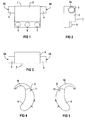
- Figures 4 and 5 show side views of one behind the Ear portable hearing aid according to the arrangement of a microphone the invention.
- FIG. 6 shows a hearing aid that can be worn behind the ear Section with a microphone arranged according to the invention.
- Figure 7 shows a microphone in cross section.
- Figure 1 shows a microphone 1 in plan view.
- the microphone 1 has a microphone housing 2, on the two opposite A sound inlet connection 3 or 4 is arranged on each side is.
- the sound inlet connection 3 and 4 form on their free end each a sound entry opening 3A or 4A and lead through the other end to a microphone chamber inside of the microphone 1.
- the microphone 1 comprises three Contacts 5, 6 and 7.
- Figure 2 shows the microphone 1 in a side view.
- the housing 2 To the Housing 2 is the one pointing out from the drawing level Sound inlet connection 3 with the sound inlet opening 3A arranged. Furthermore, the drawing is the electrical connection contact 5 removable.
- FIG. 1 An end face of the microphone 1 is shown in FIG. This is also the case 2 with the two, on opposite Sound inlet ports 3 and 4 arranged on the sides seen.
- FIG. 4 and 5 is a side view of one behind wearable hearing aid 8 shown.
- the hearing aid 8 comprises a hearing aid housing 9, at its upper end Support hook 10 is integrally formed.
- On two opposite sides of the housing the hearing aid housing 9 each has a sound inlet opening 11 or 12, in which the sound inlet connection introduced for recording the microphone according to the invention are. Due to the space-saving arrangement of the microphone of the invention in the hearing aid housing 9, the sound entry openings 11 and 12 almost arbitrarily on two opposite Sides of the hearing aid housing 9 are positioned.
- the sound inlet openings 11 and 12 are preferably located and thus the sound inlet connection of the microphone in question on a common axis.
- FIG. 6 shows a section in a simplified representation through the hearing aid housing 9.
- Two opposite housing shells 9A and 9B each have a sound inlet opening 11 or 12 on the two housing bushings 11A or 12A are formed.
- the microphone 1 is on both sides of the sound inlet connection 3 and 4 worn, the form-fitting in the two Housing bushings 11A and 12A are used.
- the microphone 1 also has the electrical Contacts 5, 6 and 7 open. From Figure 6 very space-saving accommodation of the microphone 1 inside of the hearing aid housing can be seen.
- the microphone holder takes place by means of the two sound inlet connections 3 and 4. This enables quick and easy assembly.
- Farther 6 are the very short sound transmission paths from the sound inlet openings 11 and 12 to the inside the microphone 1 can be removed. This has a positive effect on the acoustic properties of the hearing aid microphone unit out.
- FIG. 7 shows a microphone 13 in a schematic representation Cross-section.
- the Sound inlet stubs 15 to 18 form sound inlet openings 19 to 22.
- the sound inlet stubs 15 and 16 on one side of a microphone membrane 23 and the Sound inlet connection 17 and 18 on the opposite Side of the microphone membrane 23.
- the sound inlet connection 15 and 16 or 17 and 18 along a pair of sound inlets a common line of symmetry 24A and 24B arranged. So it is possible that through a sound inlet 19, 20, 21, 22 entering moisture or Soiling on the other side or can be blown out.
- a microphone with a microphone housing for placement in a hearing aid worn behind the ear with a hearing aid housing on two opposite On the sides of the microphone housing with a sound inlet connection arranged a sound inlet.
- the sound inlet connection open into a chamber on one side of the microphone membrane, where the sound inlet connection in one recording inserted in opposite sides of the hearing aid housing are and at least approximately when the hearing aid is worn the sound inlet opening of a sound inlet nozzle distal and the other's sound inlet Sound inlet connector is arranged proximal to the head.
Landscapes
- Health & Medical Sciences (AREA)
- General Health & Medical Sciences (AREA)
- Neurosurgery (AREA)
- Otolaryngology (AREA)
- Physics & Mathematics (AREA)
- Engineering & Computer Science (AREA)
- Acoustics & Sound (AREA)
- Signal Processing (AREA)
- Headphones And Earphones (AREA)
- Circuit For Audible Band Transducer (AREA)
- Details Of Audible-Bandwidth Transducers (AREA)
Abstract
Description
Claims (4)
- Hinter dem Ohr tragbares Hörgerät (8) mit einem Hörgerätegehäuse (9) und einem in dem Hörgerätegehäuse angeordneten Mikrofon (1, 13) mit einem Mikrofongehäuse (2, 14), dadurch gekennzeichnet, dass das Hörgerätegehäuse in gegenüberliegenden Seiten je eine Schalleintrittsöffnung (11, 12) aufweist und an zwei gegenüberliegenden Seiten des Mikrofongehäuses (2, 14) je ein Schalleintrittsstutzen (3, 4, 15, 16, 17, 18) mit einer Schalleintrittsöffnung (3A, 4A, 19, 20, 21, 22) angeordnet ist, wobei die Schalleintrittsstutzen (3, 4, 15, 16, 17, 18) in die Schalleintrittsöffnungen (11, 12) des Hörgerätegehäuses (9) hineinragen und wobei bei getragenem Hörgerät (8) zumindest näherungsweise die Schalleintrittsöffnung (3A) des einen Schalleintrittsstutzens (3) distal und die Schalleintrittsöffnung (4A) des anderen Schalleintrittsstutzens (4) proximal zum Kopf eines Hörgeräteträgers angeordnet ist.
- Hinter dem Ohr tragbares Hörgerät (8) nach Anspruch 1, dadurch gekennzeichnet, dass das Mikrofon (13) mehrere Paare von Schalleintrittsstutzen (15, 16, 17, 18) umfasst, wobei die Schalleintrittsstutzen eines Paares auf gegenüberliegenden Seiten des Mikrofongehäuses angeordnet sind.
- Hinter dem Ohr tragbares Hörgerät (8) nach Anspruch 2, dadurch gekennzeichnet, dass die Schalleintrittsstutzen (15, 16; 17, 18) eines Paares in eine Kammer (25, 26) auf einer Seite einer Mikrofonmembran (23) münden.
- Hinter dem Ohr tragbares Hörgerät (8) nach einem der Ansprüche 1 bis 3, dadurch gekennzeichnet, dass jeweils zwei Schalleintrittsstutzen (3, 4; 15, 16; 17, 18) sowie jeweils zwei Schalleintrittsöffnungen (11, 12) in gegenüberliegenden Seiten des Hörgerätegehäuses (9) auf einer gemeinsamen Symmetrieachse (24A, 24B) angeordnet sind.
Applications Claiming Priority (2)
| Application Number | Priority Date | Filing Date | Title |
|---|---|---|---|
| DE10131214A DE10131214C1 (de) | 2001-06-28 | 2001-06-28 | Mikrofonanordnung in einem hinter dem Ohr tragbaren Hörgerät |
| DE10131214 | 2001-06-28 |
Publications (3)
| Publication Number | Publication Date |
|---|---|
| EP1272002A2 true EP1272002A2 (de) | 2003-01-02 |
| EP1272002A3 EP1272002A3 (de) | 2009-04-15 |
| EP1272002B1 EP1272002B1 (de) | 2009-12-02 |
Family
ID=7689785
Family Applications (1)
| Application Number | Title | Priority Date | Filing Date |
|---|---|---|---|
| EP02013819A Expired - Lifetime EP1272002B1 (de) | 2001-06-28 | 2002-06-21 | Mikrofonanordnung in einem hinter dem Ohr tragbaren Hörgerät |
Country Status (5)
| Country | Link |
|---|---|
| US (1) | US6724903B2 (de) |
| EP (1) | EP1272002B1 (de) |
| AT (1) | ATE450984T1 (de) |
| DE (2) | DE10131214C1 (de) |
| DK (1) | DK1272002T3 (de) |
Cited By (1)
| Publication number | Priority date | Publication date | Assignee | Title |
|---|---|---|---|---|
| EP2323422A4 (de) * | 2008-07-30 | 2013-03-20 | Funai Electric Co | Differenzialmikrofon |
Families Citing this family (10)
| Publication number | Priority date | Publication date | Assignee | Title |
|---|---|---|---|---|
| DK1692918T3 (en) * | 2003-12-05 | 2018-11-26 | Oticon As | MICROPHONE COMMUNICATION DEVICE |
| US7542580B2 (en) * | 2005-02-25 | 2009-06-02 | Starkey Laboratories, Inc. | Microphone placement in hearing assistance devices to provide controlled directivity |
| US8121320B2 (en) * | 2008-01-11 | 2012-02-21 | Songbird Hearing, Inc. | Hearing aid |
| USD605769S1 (en) | 2008-06-26 | 2009-12-08 | Songbird Hearing, Inc. | Hearing aid part |
| USD605292S1 (en) | 2008-06-26 | 2009-12-01 | Songbird Hearing, Inc. | Hearing aid earpiece |
| USD620926S1 (en) | 2008-10-04 | 2010-08-03 | Victor Kingsun Wai | Sound amplification ear device |
| US20110085685A1 (en) * | 2009-10-08 | 2011-04-14 | Victor Kingsun Wai | Sound Amp Ear Device with Ear Phone Jack |
| USD650080S1 (en) | 2009-11-03 | 2011-12-06 | Songbird Hearing, Inc. | Hearing aid part |
| KR102008374B1 (ko) * | 2012-08-03 | 2019-10-23 | 삼성전자주식회사 | 휴대용 단말기의 입력장치 |
| EP4084109A1 (de) | 2015-12-15 | 2022-11-02 | Merck Patent GmbH | Ester mit aromatischen gruppen als lösungsmittel für organische elektronische formulierungen |
Family Cites Families (4)
| Publication number | Priority date | Publication date | Assignee | Title |
|---|---|---|---|---|
| NL8802516A (nl) | 1988-10-13 | 1990-05-01 | Philips Nv | Hoorapparaat met rondzing onderdrukking. |
| DE29621611U1 (de) * | 1996-12-12 | 1997-02-27 | Siemens Audiologische Technik Gmbh, 91058 Erlangen | Mikrofon, insbesondere für elektrische Hörhilfegeräte |
| US6151399A (en) * | 1996-12-31 | 2000-11-21 | Etymotic Research, Inc. | Directional microphone system providing for ease of assembly and disassembly |
| DE19852758C2 (de) * | 1998-11-16 | 2001-05-23 | Siemens Audiologische Technik | Hinter dem Ohr tragbares Hörhilfegerät |
-
2001
- 2001-06-28 DE DE10131214A patent/DE10131214C1/de not_active Expired - Fee Related
-
2002
- 2002-06-21 AT AT02013819T patent/ATE450984T1/de not_active IP Right Cessation
- 2002-06-21 DK DK02013819.4T patent/DK1272002T3/da active
- 2002-06-21 DE DE50214032T patent/DE50214032D1/de not_active Expired - Lifetime
- 2002-06-21 EP EP02013819A patent/EP1272002B1/de not_active Expired - Lifetime
- 2002-06-28 US US10/185,311 patent/US6724903B2/en not_active Expired - Fee Related
Cited By (2)
| Publication number | Priority date | Publication date | Assignee | Title |
|---|---|---|---|---|
| EP2323422A4 (de) * | 2008-07-30 | 2013-03-20 | Funai Electric Co | Differenzialmikrofon |
| US8457342B2 (en) | 2008-07-30 | 2013-06-04 | Funai Electric Co., Ltd. | Differential microphone |
Also Published As
| Publication number | Publication date |
|---|---|
| US20030002701A1 (en) | 2003-01-02 |
| DK1272002T3 (da) | 2010-03-29 |
| ATE450984T1 (de) | 2009-12-15 |
| EP1272002B1 (de) | 2009-12-02 |
| US6724903B2 (en) | 2004-04-20 |
| EP1272002A3 (de) | 2009-04-15 |
| DE10131214C1 (de) | 2003-01-09 |
| DE50214032D1 (de) | 2010-01-14 |
Similar Documents
| Publication | Publication Date | Title |
|---|---|---|
| DE69919907T2 (de) | Sauerstoffinhalationsmaske mit schallaufnahmevorrichtung | |
| CH664057A5 (de) | Hoergeraet. | |
| EP1272002B1 (de) | Mikrofonanordnung in einem hinter dem Ohr tragbaren Hörgerät | |
| EP0136643A2 (de) | Hörgerät | |
| DE60117779T2 (de) | "akustische bertragungsverbindung, kopfsprechhvrer mit akustischer bertragungsverbindung und verwendungen der akustischen bertragungsverbindung" | |
| DE2258118B2 (de) | Hörgerät | |
| EP0219026A1 (de) | Hörgerät | |
| DE10260304B3 (de) | Hörgerätesystem mit seitenspezifisch ausgebildeten hinter den Ohren tragbaren Hörhilfegeräten | |
| DE102009056916A1 (de) | Hörgerät mit einer platzsparenden Anordnung von Mikrofonen und Schallöffnungen | |
| DE102017128117A1 (de) | Modulares Hörgerät | |
| DE69613706T2 (de) | Montageanordnung eines geräuschunterdrückenden mikrofons | |
| DE10354147B4 (de) | Medizinische Steckverbindungsvorrichtung mit einem Stecker und einer Kupplung | |
| CH643414A5 (en) | Hearing-aid with plug device | |
| DE102004044318B3 (de) | Schlauchförmige Verbindungsleitung für ein Hörgerät und Hörgerät | |
| DE102005009377B3 (de) | Im-Ohr-Hörgerät mit abnehmbarem Lautsprecher | |
| EP3355591A1 (de) | Mikrofoneinheit mit einem gehäuse | |
| DE102017210448B3 (de) | Hörgerät | |
| DE19908194C1 (de) | Hinter dem Ohr tragbares Hörhilfegerät | |
| DE3921551A1 (de) | Gehaeuse fuer ein hinter dem ohr zu tragendes hoergeraet | |
| CH702286B1 (de) | Hochfrequenz-Anschlussplatte | |
| DE19626933C5 (de) | Handapparat für Telefone | |
| DE3149061A1 (de) | Wechselsprechgeraet | |
| DE102006045484B4 (de) | Hörgerät | |
| DE102007003248A1 (de) | Hörgerät | |
| DE2362874A1 (de) | Mit einem elektret ausgeruestetes kondensatormikrophon, insbesondere fuer hoerbrillen |
Legal Events
| Date | Code | Title | Description |
|---|---|---|---|
| PUAI | Public reference made under article 153(3) epc to a published international application that has entered the european phase |
Free format text: ORIGINAL CODE: 0009012 |
|
| AK | Designated contracting states |
Kind code of ref document: A2 Designated state(s): AT BE CH CY DE DK ES FI FR GB GR IE IT LI LU MC NL PT SE TR |
|
| AX | Request for extension of the european patent |
Free format text: AL;LT;LV;MK;RO;SI |
|
| PUAL | Search report despatched |
Free format text: ORIGINAL CODE: 0009013 |
|
| AK | Designated contracting states |
Kind code of ref document: A3 Designated state(s): AT BE CH CY DE DK ES FI FR GB GR IE IT LI LU MC NL PT SE TR |
|
| AX | Request for extension of the european patent |
Extension state: AL LT LV MK RO SI |
|
| 17P | Request for examination filed |
Effective date: 20090406 |
|
| GRAP | Despatch of communication of intention to grant a patent |
Free format text: ORIGINAL CODE: EPIDOSNIGR1 |
|
| GRAS | Grant fee paid |
Free format text: ORIGINAL CODE: EPIDOSNIGR3 |
|
| GRAA | (expected) grant |
Free format text: ORIGINAL CODE: 0009210 |
|
| AK | Designated contracting states |
Kind code of ref document: B1 Designated state(s): AT BE CH CY DE DK ES FI FR GB GR IE IT LI LU MC NL PT SE TR |
|
| REG | Reference to a national code |
Ref country code: GB Ref legal event code: FG4D Free format text: NOT ENGLISH |
|
| REG | Reference to a national code |
Ref country code: CH Ref legal event code: EP Ref country code: CH Ref legal event code: NV Representative=s name: SIEMENS SCHWEIZ AG |
|
| AKX | Designation fees paid |
Designated state(s): AT BE CH CY DE DK ES FI FR GB GR IE IT LI LU MC NL PT SE TR |
|
| REG | Reference to a national code |
Ref country code: IE Ref legal event code: FG4D |
|
| REF | Corresponds to: |
Ref document number: 50214032 Country of ref document: DE Date of ref document: 20100114 Kind code of ref document: P |
|
| REG | Reference to a national code |
Ref country code: DK Ref legal event code: T3 |
|
| REG | Reference to a national code |
Ref country code: NL Ref legal event code: VDEP Effective date: 20091202 |
|
| PG25 | Lapsed in a contracting state [announced via postgrant information from national office to epo] |
Ref country code: FI Free format text: LAPSE BECAUSE OF FAILURE TO SUBMIT A TRANSLATION OF THE DESCRIPTION OR TO PAY THE FEE WITHIN THE PRESCRIBED TIME-LIMIT Effective date: 20091202 Ref country code: SE Free format text: LAPSE BECAUSE OF FAILURE TO SUBMIT A TRANSLATION OF THE DESCRIPTION OR TO PAY THE FEE WITHIN THE PRESCRIBED TIME-LIMIT Effective date: 20091202 |
|
| PG25 | Lapsed in a contracting state [announced via postgrant information from national office to epo] |
Ref country code: CY Free format text: LAPSE BECAUSE OF FAILURE TO SUBMIT A TRANSLATION OF THE DESCRIPTION OR TO PAY THE FEE WITHIN THE PRESCRIBED TIME-LIMIT Effective date: 20091202 |
|
| REG | Reference to a national code |
Ref country code: IE Ref legal event code: FD4D |
|
| PG25 | Lapsed in a contracting state [announced via postgrant information from national office to epo] |
Ref country code: ES Free format text: LAPSE BECAUSE OF FAILURE TO SUBMIT A TRANSLATION OF THE DESCRIPTION OR TO PAY THE FEE WITHIN THE PRESCRIBED TIME-LIMIT Effective date: 20100313 Ref country code: PT Free format text: LAPSE BECAUSE OF FAILURE TO SUBMIT A TRANSLATION OF THE DESCRIPTION OR TO PAY THE FEE WITHIN THE PRESCRIBED TIME-LIMIT Effective date: 20100402 Ref country code: IE Free format text: LAPSE BECAUSE OF FAILURE TO SUBMIT A TRANSLATION OF THE DESCRIPTION OR TO PAY THE FEE WITHIN THE PRESCRIBED TIME-LIMIT Effective date: 20091202 |
|
| PLBE | No opposition filed within time limit |
Free format text: ORIGINAL CODE: 0009261 |
|
| STAA | Information on the status of an ep patent application or granted ep patent |
Free format text: STATUS: NO OPPOSITION FILED WITHIN TIME LIMIT |
|
| PG25 | Lapsed in a contracting state [announced via postgrant information from national office to epo] |
Ref country code: GR Free format text: LAPSE BECAUSE OF FAILURE TO SUBMIT A TRANSLATION OF THE DESCRIPTION OR TO PAY THE FEE WITHIN THE PRESCRIBED TIME-LIMIT Effective date: 20100303 |
|
| 26N | No opposition filed |
Effective date: 20100903 |
|
| BERE | Be: lapsed |
Owner name: SIEMENS AUDIOLOGISCHE TECHNIK G.M.B.H. Effective date: 20100630 |
|
| PG25 | Lapsed in a contracting state [announced via postgrant information from national office to epo] |
Ref country code: MC Free format text: LAPSE BECAUSE OF NON-PAYMENT OF DUE FEES Effective date: 20100630 |
|
| PG25 | Lapsed in a contracting state [announced via postgrant information from national office to epo] |
Ref country code: IT Free format text: LAPSE BECAUSE OF FAILURE TO SUBMIT A TRANSLATION OF THE DESCRIPTION OR TO PAY THE FEE WITHIN THE PRESCRIBED TIME-LIMIT Effective date: 20091202 |
|
| PG25 | Lapsed in a contracting state [announced via postgrant information from national office to epo] |
Ref country code: BE Free format text: LAPSE BECAUSE OF NON-PAYMENT OF DUE FEES Effective date: 20100630 |
|
| PGFP | Annual fee paid to national office [announced via postgrant information from national office to epo] |
Ref country code: FR Payment date: 20110630 Year of fee payment: 10 |
|
| PG25 | Lapsed in a contracting state [announced via postgrant information from national office to epo] |
Ref country code: AT Free format text: LAPSE BECAUSE OF NON-PAYMENT OF DUE FEES Effective date: 20100621 |
|
| PGFP | Annual fee paid to national office [announced via postgrant information from national office to epo] |
Ref country code: DK Payment date: 20110610 Year of fee payment: 10 Ref country code: GB Payment date: 20110613 Year of fee payment: 10 |
|
| PGFP | Annual fee paid to national office [announced via postgrant information from national office to epo] |
Ref country code: CH Payment date: 20110914 Year of fee payment: 10 |
|
| PGFP | Annual fee paid to national office [announced via postgrant information from national office to epo] |
Ref country code: DE Payment date: 20110819 Year of fee payment: 10 |
|
| PG25 | Lapsed in a contracting state [announced via postgrant information from national office to epo] |
Ref country code: LU Free format text: LAPSE BECAUSE OF NON-PAYMENT OF DUE FEES Effective date: 20100621 |
|
| PG25 | Lapsed in a contracting state [announced via postgrant information from national office to epo] |
Ref country code: TR Free format text: LAPSE BECAUSE OF FAILURE TO SUBMIT A TRANSLATION OF THE DESCRIPTION OR TO PAY THE FEE WITHIN THE PRESCRIBED TIME-LIMIT Effective date: 20091202 |
|
| REG | Reference to a national code |
Ref country code: DK Ref legal event code: EBP |
|
| REG | Reference to a national code |
Ref country code: CH Ref legal event code: PL |
|
| REG | Reference to a national code |
Ref country code: CH Ref legal event code: PL |
|
| GBPC | Gb: european patent ceased through non-payment of renewal fee |
Effective date: 20120621 |
|
| REG | Reference to a national code |
Ref country code: FR Ref legal event code: ST Effective date: 20130228 |
|
| REG | Reference to a national code |
Ref country code: DE Ref legal event code: R119 Ref document number: 50214032 Country of ref document: DE Effective date: 20130101 |
|
| PG25 | Lapsed in a contracting state [announced via postgrant information from national office to epo] |
Ref country code: LI Free format text: LAPSE BECAUSE OF NON-PAYMENT OF DUE FEES Effective date: 20120630 Ref country code: CH Free format text: LAPSE BECAUSE OF NON-PAYMENT OF DUE FEES Effective date: 20120630 Ref country code: GB Free format text: LAPSE BECAUSE OF NON-PAYMENT OF DUE FEES Effective date: 20120621 Ref country code: DE Free format text: LAPSE BECAUSE OF NON-PAYMENT OF DUE FEES Effective date: 20130101 Ref country code: FR Free format text: LAPSE BECAUSE OF NON-PAYMENT OF DUE FEES Effective date: 20120702 |
|
| PG25 | Lapsed in a contracting state [announced via postgrant information from national office to epo] |
Ref country code: DK Free format text: LAPSE BECAUSE OF NON-PAYMENT OF DUE FEES Effective date: 20120702 |
|
| PG25 | Lapsed in a contracting state [announced via postgrant information from national office to epo] |
Ref country code: NL Free format text: LAPSE BECAUSE OF FAILURE TO SUBMIT A TRANSLATION OF THE DESCRIPTION OR TO PAY THE FEE WITHIN THE PRESCRIBED TIME-LIMIT Effective date: 20091202 |