EP1272012A1 - Light source device - Google Patents
Light source device Download PDFInfo
- Publication number
- EP1272012A1 EP1272012A1 EP02014232A EP02014232A EP1272012A1 EP 1272012 A1 EP1272012 A1 EP 1272012A1 EP 02014232 A EP02014232 A EP 02014232A EP 02014232 A EP02014232 A EP 02014232A EP 1272012 A1 EP1272012 A1 EP 1272012A1
- Authority
- EP
- European Patent Office
- Prior art keywords
- high voltage
- generating part
- voltage generating
- light source
- source device
- Prior art date
- Legal status (The legal status is an assumption and is not a legal conclusion. Google has not performed a legal analysis and makes no representation as to the accuracy of the status listed.)
- Granted
Links
Images




Classifications
-
- H—ELECTRICITY
- H05—ELECTRIC TECHNIQUES NOT OTHERWISE PROVIDED FOR
- H05B—ELECTRIC HEATING; ELECTRIC LIGHT SOURCES NOT OTHERWISE PROVIDED FOR; CIRCUIT ARRANGEMENTS FOR ELECTRIC LIGHT SOURCES, IN GENERAL
- H05B41/00—Circuit arrangements or apparatus for igniting or operating discharge lamps
- H05B41/14—Circuit arrangements
- H05B41/26—Circuit arrangements in which the lamp is fed by power derived from DC by means of a converter, e.g. by high-voltage DC
- H05B41/28—Circuit arrangements in which the lamp is fed by power derived from DC by means of a converter, e.g. by high-voltage DC using static converters
- H05B41/288—Circuit arrangements in which the lamp is fed by power derived from DC by means of a converter, e.g. by high-voltage DC using static converters with semiconductor devices and specially adapted for lamps without preheating electrodes, e.g. for high-intensity discharge lamps, high-pressure mercury or sodium lamps or low-pressure sodium lamps
- H05B41/292—Arrangements for protecting lamps or circuits against abnormal operating conditions
Definitions
- the invention relates to a light source device using a HID lamp which is used for example as a light source for a projector.
- a discharge lamp with high radiance lamp such as a high pressure mercury lamp, a xenon lamp, a metal halide lamp or the like is used.
- HID high radiance lamp
- FIG 14 shows the arrangement of a conventional discharge lamp light source device of the series trigger type.
- a starter Ui
- a pulsed high voltage is applied between the electrodes (E1, E2) of the two poles of the discharge lamp.
- the secondary winding (Si) of the high voltage transformer (Ti) of the starter is series-connected to the discharge lamp (Li). After starting a discharge the function of the starter is no longer necessary.
- the discharge current supplied to the lamp (Li) must nonetheless flow via the secondary winding (Si) of the high voltage transformer, which has a large number of windings.
- it is necessary to make the wire diameter of the winding large which inevitably results in the disadvantage of an increase in size and weight of the starter.
- One method for avoiding this disadvantage has been to use an outside trigger method which is often used for the trigger of a blinking lamp.
- this method in addition to the first electrode and the second electrode of the two poles which form the main arc discharge after starting, there is provided an auxiliary electrode, positioned between either the first or the second electrode to which a high voltage is applied. This results in dielectric barrier discharge plasma being produced in the discharge space, which then creates the main arc discharge between the first electrode and the second electrode by means of a voltage which has been applied beforehand, i.e., a no-load voltage, by means of a plasma.
- the discharge lamp (Li) and the feed device (Ni) are connected to one another by feed lines (K1, K2).
- the starter (Ui) unit is located inside the feed device (Ni). This starter (Ui) must produce a high voltage, e.g., a high pulsed voltages so that the feed lines (K1, K2) are charged in a short time with a high voltage which results in the disadvantage of creating a powerful noise in the lines.
- the pulse width is broadened by dulling distortion of the pulsed high voltage which increases the possibility of the formation of an insulation breakdown in an unintended area, such as in the insulation coating of the high voltage transformer (Ti) and the feed lines (K1, K2) or the like. This reduces the reliability of the discharge lamp.
- a starter In another method of starting a discharge lamp, a starter, referred to as a DC starter, produces a high voltage where the voltage increases relatively slowly. However, in this instance the insulation breakdown phenomenon is more frequent, as well as resulting in a higher voltage and a longer voltage application time. The disadvantage in this method is an even greater possibility exists for the formation of an insulation breakdown in an unintended area.
- Japanese patent publication JP 37-8045 discloses a discharge lamp in which the technique for starting the high pressure discharge lamp is by the outside trigger method. In this arrangement, there is a coil which produces, at the lamp current in the high pressure mercury lamp, a magnetic force. The operation of the starter circuit is controlled so that a high voltage is produced in an auxiliary electrode by the magnetic force.
- a lamp arrangement is disclosed in which in a lamp, such as a high voltage mercury lamp or the like, a plurality of auxiliary electrodes (outside electrodes) are provided which are situated a few millimeters from one another.
- a lamp such as a high voltage mercury lamp or the like
- auxiliary electrodes outer electrodes
- the object of the invention is to eliminate the disadvantages described above, which can be summarized as:
- a connector for electrical connection of the feed circuit part (By) to the unit (Ly) has the additional function of a holding means for the high voltage generating part (Ub).
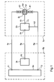
- Figure 1 sets forth a block drawing of a light source device according to a first embodiment of the invention
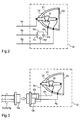
- Figure 2 sets forth a schematic of an arrangement of lamp parts of the light source device according to another embodiment of the invention.
- Figure 3 sets forth a schematic of a first variation of the light source device of Figure 2;
- Figure 4 sets forth a schematic of a second variation of the light source device of Figure 2;
- FIG. 5 sets forth a detailed schematic of the first embodiment of the invention of Figure 1;
- FIG 6 sets forth another detailed schematic of the first embodiment of the invention of Figure 1;
- Figure 7 sets forth a detailed cross section of the first variation of the light source device of Figure 3;
- Figure 8 sets forth another detailed cross section of a variation of the light source device of Figure 3;
- Figure 9 sets forth a detailed cross section of the second variation of the light source device of Figure 4.
- Figure 10 sets forth another detailed cross section of a variation of the light source device of Figure 4.
- FIG 11 sets forth a schematic of an embodiment of the invention in which another starter is used
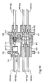
- Figure 12 shows another schematic of an embodiment of the invention in which yet another starter is used
- Figure 13 sets forth a schematic of an embodiment of the invention in which an alternating discharge voltage is applied.
- Figure 14 sets forth a schematic of a conventional light source device.
- Figure 1 shows the overall arrangement of a light source device of the invention in a simplified block drawing.
- the high voltage generating part (Ub) of the starter circuit which comprises at least one high voltage transformer and the lamp (Ld), are formed as an integral lamp unit (Ly).
- the starter drive part (Ua) is separate from the high voltage generating part (Ub) of the starter circuit.
- the starter drive part (Ua) together with the feed circuit (Bx) for supply of electrical energy for the discharge emission to the lamp (Ld) is located in the feed circuit part (By).
- FIG. 2 shows the arrangement of parts of the lamp unit (Ly) of the light source device of the invention in a simplified representation.
- a lamp is described in which a reflector (Y1) for emergence of the emission of the lamp in a certain direction and a light exit window (Y2) which envelops the front side of the reflector (Y1) are used.
- the length of the line path (Kh) of the high voltage for connection of the switching part on the secondary side of the high voltage transformer (Te) to the auxiliary electrode (Et) can be reduced since the high voltage generating part (Ub) of the starter circuit including at least the high voltage transformer (Te in Figures 5 & 6) is separated from the feed circuit part (By) and that the above lamp (Ld) and the high voltage generating part (Ub) are formed as an integral lamp unit (Ly).
- the electrostatic capacity which is formed between the line path (Kh) of the high voltage for connection of the switching part on the secondary side of the high voltage transformer (Te) to the auxiliary electrode (Et) and the lead in the vicinity can be reduced and the inductance of the line path (Kh) can be decreased.
- the length of the connecting line between the starter and the auxiliary electrode (Et) is small, the possibility of formation of an insulation breakdown in an unintended area can also be suppressed when the starter produces a high voltage where the voltage increases relatively slowly. Furthermore, the high voltage-carrying lines in the line paths (Kv, Kp, Kg) between the feed circuit part (By) and the lamp unit (Ly) are no longer necessary. As a result, a line with low voltage stability, thin insulation coating and a small coating diameter can be used. Therefore, it is possible to contribute to a reduction in the size of the light source device more than in the case in which a thick, high voltage-carrying line is used. As a result, the installation effort is simplified, and the costs for development and production of the light source device can be reduced.
- the arrangement of the light source device of the invention described in this first embodiment eliminates the disadvantages of having to deliver a greater energy than necessary by the starter, of noise, and the danger of insulation breakdown in an unintended area. Additionally, the light source device can be built at low production costs, and an increase both in the size and weight of the starter can be avoided.
- Figure 3 shows a first variation of this embodiment of the invention.
- the connector (Ca, Cb) on the side of the lamp unit also have the function of a holding means for the high voltage generating part (Ub).
- This arrangement obviates the need for a means to attach the high voltage generating part (Ub) in the lamp unit (Ly).
- connection of the connector to the high voltage generating part (Ub) within the connector (Cb) takes place.
- a cable for connection of the connector to the high voltage generating part (Ub) is no longer necessary. Therefore, it is possible to contribute to a reduction in the size of the lamp unit (Ly).
- the high voltage generating part (Ub) is automatically replaced by this arrangement when the lamp unit (Ly) is replaced, together with the connector (Cb) on the side of the lamp unit, after the service life of the lamp (Ld) expires.
- the high voltage generating part (Ub) is replaced by a new part.
- the danger of insulation breakdown as a result of the degradation of the insulation efficiency of the high voltage generating part (Te) can be prevented beforehand.
- this arrangement makes it possible to handle the high voltage generating part (Ub) as a consumable. Therefore, its service life can be limited to a limited starting frequency per lamp (Ld).
- the reliability which can be required of the high voltage generating part (Ub) can be improved compared to the conventional lamps where it is used as a long-term part. As a result, the costs for the arrangement of the high voltage generating part (Ub) and for the materials used for this part can be reduced.
- Figure 4 shows another variation of the second embodiment of the invention.
- the connectors (Ca', Cb') for electrical connection of the feed circuit part (By) to the lamp unit (Ly) in which the connector (Ca') is paired with the connector (Cb') on the side of the lamp unit, also have the function of a holding means for the high voltage generating part (Ub).
- a means for mounting the high voltage generating part (Ub) in the lamp unit (Ly) and a cable for connection of the connector to the high voltage generating part (Ub) are no longer necessary.
- the difference is in handling of the high voltage generating part (Ub) either as a consumable or a permanent part. Since each variation still has other advantages, i.e., with respect to costs and reliability and the like, the variation can be selected which is more advantageous at the time.
- a lamp arrangement can be provided in which the connectors for electrical connection of the feed circuit part (By) to the lamp unit (Ly), on both the connector on the side of the lamp unit as well as the connector which forms a pair with this connector, have the function of a means for securing part of the starter.
- FIG. 5 illustrates one embodiment of Figure 1 in a simplified representation.
- a DC source (Mx) which can be a power factor corrector (PFC) or the like, is connected to a feed circuit (Bx) of the voltage reduction chopper-type.
- a switching device (Qx) such as a FET or the like
- the current from the DC source (Mx) is turned on and off, and a smoothing capacitor (Cx) is charged via a choke coil (Lx).
- a gate signal with a suitable pulse duty factor from a gate driver circuit (Gx) is transferred to the switching device (Qx) such that the discharge current which flows between the electrodes (E1, E2) for the main discharge of the lamp (Ld).
- the voltage between the electrodes (E1, E2) for the main discharge or the lamp wattage as the product of this current has a suitable value which corresponds to the state of the lamp (Ld) at this instant.
- a partial pressure resistance or a shunt resistance is provided for determining the voltage of the smoothing capacitor (Cx) and the current supplied by the smoothing capacitor (Cx) of the lamp (Ld). Furthermore, there is normally a control circuit which makes it possible for the gate driver circuit (Gx) to produce a suitable gate signal.
- a charging voltage is applied to the capacitor (Ce), and to the primary winding (Pe) of the high voltage transformer (Te) of the high voltage generating part (Ub) which is separated from the feed circuit part (By) and which is formed as an integral unit (Ly).
- a secondary winding (Se) of the high voltage transformer (Te) an increased voltage is formed which corresponds to the arrangement of the high voltage transformer (Te).
- the voltage applied to the primary winding (Pe) decreases rapidly according to the discharge of the capacitor (Ce).
- the voltage which forms in the secondary winding (Se) similarly drops rapidly.
- the voltage which forms in the secondary winding (Se) therefore becomes a pulse.
- One end of the secondary winding (Se) of the high voltage transformer (Te) is connected to one of the electrodes of the lamp (Ld), specifically to the electrode (E1), which in this instance is the cathode.
- the other end of the secondary winding (Se) is connected to the auxiliary electrode (Et) which is located outside of the discharge vessel of the lamp (Ld).
- the high voltage which forms in the secondary winding (Se) produces a discharge between the auxiliary electrode (E1) of the lamp (Ld) and the inside of the discharge vessel of the lamp (Ld) through a dielectric barrier discharge.
- the main discharge is induced between the electrode (E1) and the other electrode (E2).
- the high voltage of the starter is applied between the cathode side of the lamp and the auxiliary electrode.
- the high voltage can also be applied between the anode side of the lamp and the auxiliary electrode.
- the starter drive part (Ua) and the high voltage generating part (Ub) are connected by a line (Kp) which leads to one end of the primary winding (Pe) of the high voltage transformer (Te).
- the other end of the primary winding (Pe) of the high voltage transformer (Te) is connected via a terminal (F2') to an electrical circuit (Kg) which is a ground that is combined with the electrode (E1) of the lamp (Ld).
- the light source device can be operated by a connection of the feed circuit part (By) to the lamp unit (Ly) by only three lines (Kv, Kp, Kg), where line (Kv) connects to the anode (E2) of the lamp (Ld). Consequently, the advantage that the number of lines can be reduced is realized.
- the line (Kg) of the ground is used jointly for the current of the main discharge of the lamp (Ld) and for the current of the primary winding (Pe) of the high voltage transformer (Te) of the high voltage generating part (Ub), the circuit is not balanced so it is possible for noise to form, for example from the line (Kp), for the current of the primary winding (Pe) of the high voltage transformer (Te).
- the reason why the lines can be twisted in this embodiment is that in the situation when the high voltage generating part (Ub), which comprises the high voltage transformer (Te), is separated from the feed circuit part (By) and the lamp (Ld) and the high voltage generating part (Ub) are formed as a one-part unit (Ly), there is no need to lay a high voltage-carrying line for the line paths between the feed circuit part (By) and the lamp unit (Ly). As a result, a line with low voltage stability, a thin insulation coating and a small coating diameter can be used which is a major advantage of the invention.
- Figure 7 illustrates a detailed cross section of the first variation of the light source device of Figure 3 in a simplified representation.
- the circuit corresponds to the circuit described above using Figure 5.
- the line (Kg) is connected to the cathode (E1) of the lamp (Ld) by a contact of the contactor (015) to which the cable conductor of a cable (007) is connected.
- a contactor (016) is provided to which the cable conductor of a cable (008) is connected.
- the line (Kv) to the anode (E2) of the lamp (Ld) is connected by a contactor (017) with the cable conductor of the cable (009), and with a contactor (018) to which the cable conductor of a cable (010) is connected.
- the line (Kp) between the starter drive part (Ua) and the high voltage generating part (Ub) is connected by the contact of a contactor (111) to the cable conductor of a cable (003), and with a contactor (112) to which one terminal (F4) of the high voltage generating part (Ub), located in a cage-like connector body (102), is directly connected.
- the terminal (F2') which is to be connected to the ground line path (Kg) of the high voltage generating part (Ub), is directly connected to the contactor (016).
- the cable conductor of the high voltage cable (004) is connected to the high voltage output terminal (F3) of the high voltage generating part (Ub).
- Figure 8 similarly shows, in a simplified representation, another cross section of a variation of the light source device of Figure 3.
- the arrangement of the connectors (Ca, Cb) in this variation includes a connector (Cb) on the side of the lamp unit that also functions as a receiving vessel and holding means for the high voltage generating part (Ub).
- the circuit corresponds to the circuit described above using Figure 6.
- a pair of contact arrangements are added to the cage-like connector bodies (141, 142).
- An additional line (Kp') between the starter drive part (Ua) and the high voltage generating part (Ub) is connected by a contact of the contactor (013) to which the cable conductor of a cable (005) is connected, and with a contactor (014) to which one terminal (F2') of the high voltage generating part (Ub) is directly connected.
- Figure 9 illustrates a cross section of the second variation of the light source device of Figure 4 in a simplified representation.
- the arrangement of connectors (Ca', Cb') in this instance is such that the connector (Ca'), which forms a pair with the connector (Cb') on the side of the lamp unit, also functions of a receiving part and a holding means for the high voltage generating part (Ub).
- the circuit corresponds to the circuit described above using Figure 5.
- a terminal (F2') is to be connected to the ground line (Kg) of the high voltage generating part (Ub) that is connected with contactor (015).
- a high voltage-carrying line (Kh) is connected on one end by one contact of a contactor (211) and at another end by a high voltage output terminal (F3) directly connected to the high voltage generating part (Ub).
- the contactor (212) also connects to the high voltage cable (004).
- Figure 10 similarly shows, in a simplified representation, another cross section of a variation of the light source device of Figure 4.
- the arrangement of connectors (Ca', Cb') in this instance is such that the connector (Ca'), which forms a pair with the connector (Cb') on the side of the lamp unit, also functions of a receiving part and a holding means for the high voltage generating part (Ub).
- the circuit corresponds to the circuit described in Figure 6.
- one line in addition is connected to the cage-like connector body (241).
- the cable conductor of the cable (005) is directly connected to one terminal (F2') of the high voltage generating part (Ub) located in the cage-like connector body (241).
- the contactor is produced by pressing a plate of a conductive material which is suitable as an elastic material, for example phosphor bronze.
- the process used will be, for example, a compression connection or the like with the contactors.
- the cable and the cage-like connector body can be coupled to one another and the terminal of the high voltage generating part (Ub) which is located in the cage-like connector body can be electrically connected to the holding body.
- a technique such as soldering, compression connection, pressure welding, clamping and the like can be used.
- a connection arrangement can be provided in which the cable coating is clamped and attached directly by a cage-like connector body or in which the cable coating is clamped by using an auxiliary component and is therefore indirectly attached to the cage-like connector body.
- a mechanism for direct or indirect attachment of the cable coating to the cage-like connector body are U-shape construction or a construction in which clamping is done by the cover of the holding chamber of the high voltage generating part (Ub).
- the cable coating can simply be cemented to the cage-like connector body.
- the cable conductor can be connected to the terminal of the high voltage generating part (Ub), e.g., by soldering or using a compression connection sleeve.
- the three-dimensional distance or creep length which is required for safety should be ensured between the high voltage output terminal (F3) of the high voltage generating part (Ub) and the charging part which is electrically connected thereto.
- FIG 11 illustrates an embodiment in which a starter is used which produces a high voltage but in which the voltage rises relatively slowly. Since the input point (F1) and the ground point (F2) of the starter drive part (Ua) are connected parallel to the lamp (Ld), as in Figures 5 and 6, the no-load voltage which has been applied to the lamp (Ld) is also supplied to the input point (F1) and the ground point (F2). When this voltage is received, charging of the capacitor (Cf1) is begun in the starter drive part (Ua) via a resistor (Rf). Closing of the switching device (Qf), such as a SIDAC or the like, takes place by itself when the voltage of the capacitor (Cf1) is charged up to a given threshold voltage.
- the switching device (Qf) such as a SIDAC or the like
- This voltage is applied to the primary winding (Pf) of the high voltage transformer (Tf) of the high voltage generating part (Ub), which is separate from the feed circuit part (By) and is formed as integral unit (Ly).
- a capacitor (Cf2) on the secondary side is charged via a diode (Df) which is connected to the secondary winding (Sf).
- the high voltage of the starter is applied between the cathode side of the lamp and the auxiliary electrode. But it can also be applied between the anode side of the lamp and the auxiliary electrode. Furthermore, the starter shown in Figure 12 can also be used; it can be considered a "two-stage voltage raising type".
- a capacitor (Ck) of the high voltage generating part (Ub) which is separate from the feed circuit part (By) and which is formed as an integral unit (Ly) is charged.
- a discharge gap element such as a surge arrestor or the like, discharges and a voltage is applied to the primary winding (Pk) of a high voltage transformer (Tk), as a result a pulsed high voltage is produced in the secondary winding (Sk) of the high voltage transformer (Tk).
- the pulsed high voltage is applied via one terminal (F3) to the auxiliary electrode (Et) which is located outside of the discharge vessel of the lamp (Ld).
- the manner of division of the components can be suitably depending on the needs of the light source device.
- a switching device (Qj) such as a SIDAC or the like, and the primary winding (Pj) of a step-up transformer are separated from one another.
- the diode (Dj) and the capacitor (Ck) can also be separated from one another or from the discharge gap element (AK) which in turn can be separated from the primary winding (Pk) of the high voltage transformer (Tk) (see boundary line S2).
- Figure 13 shows yet another embodiment of the invention in a simplified representation.
- switching devices Q1, Q2, Q3, Q4
- FETs field-effect transistors
- the switching devices are each driven by gate driver circuits (G1 G2, G3, G4) which are controlled by a full bridge inverter control circuit (Hc) such that the switches (Q1, Q4) and the switches (Q2, Q3) which are each the diagonal elements of the full bridge inverter are closed at the same time.
- G1 G2, G3, G4 gate driver circuits
- Hc full bridge inverter control circuit
- the high voltage which forms at the output points (F3, F2") of the high voltage generating part (Ub), is applied between one electrode (E1') for the main discharge of the lamp (Ld') and the auxiliary electrode (Et).
- a discharge, by which the main discharge is induced, is formed by a dielectric barrier discharge between the one electrode (E1') and the inside of the discharge vessel of the lamp (Ld').
- the timing of the switching to the closed states of the switching devices (Q1, Q2, Q3, Q4) of the full bridge inverter (and the formation of the high voltage of the starter) is unfavorable with respect to the discharge starting of the lamp, the disadvantage with respect to the timing can be avoided when the discharge start the lamp either by synchronization such that the timing of the switching of the closed states of the switching devices (Q1, Q2, Q3, Q4) and of the formation of the high voltage of the starter becomes correct, or by stopping the full bridge inverter until discharge starting of the lamp is completed.
- the starter in the circuit in Figure 13 can also be replaced by the starter which is shown above using Figure 11 and which produces a high voltage at which the voltage increases relatively slowly, although this is not shown in Figure 13.
- a feed circuit (Bx) of the voltage reduction chopper circuit type is shown.
- the advantages of the invention described above can be realized in other circuit types or in an arrangement in which the feed circuit also acts as the DC source (Mx).
- the starter drive part (Ua) is located in the feed circuit part (By).
- the starter drive part (Ua) can also be separately located.
- an embodiment where starter drive part (Ua) is essentially not present because the high voltage generating part (Ub) of the starter is the entire starter circuit is still another embodiment of the invention.
Landscapes
- Circuit Arrangements For Discharge Lamps (AREA)
- Discharge Lamps And Accessories Thereof (AREA)
- Arrangement Of Elements, Cooling, Sealing, Or The Like Of Lighting Devices (AREA)
Abstract
Description
- an undesirable increase in the size or weight of the starter should occurs when attempting to avoid heat loss in the windings;
- an undesirably large noise forms with conventional discharge lamps;
- a greater energy than necessary must be delivered as a result of capacitive coupling, in the vicinity of the starter, between the feed lines and the lead; and
- an increased possibility exists for the formation of an insulation breakdown in an unintended area which reduces the reliability of the device.
- a discharge lamp (Ld) including a pair of opposed electrodes (E1, E2) for the main arc discharge and in which an auxiliary electrode (Et) is provided so that the auxiliary electrode does not come into contact with the discharge space (Sd) for the main discharge;
- a feed circuit (Bx) for supplying the discharge current to the electrodes (E1, E2) for the main discharge; and
- a starter circuit which produces a high voltage between the one of the electrodes (E1, E2) forming the main discharge and the auxiliary electrode (Et),
- a reduction in the size of the lamp unit (Ly);
- reduced faulty connections or the like;
- an increase in reliability;
- a reduction in the labor input for connection and of the labor input for mounting the high voltage generating part (Ub) in the lamp unit (Ly) and a reduction of labor costs.
Claims (19)
- Light source device comprising:wherein the high voltage generating part of the starter circuit assembly includes at least a high voltage transformer that is separated from the feed circuit;a discharge lamp including a pair of opposed electrodes located in a discharge space and an auxiliary electrode located outside of the discharge space;a feed circuit for supplying a discharge current to the opposed electrodes; anda starter circuit assembly including a high voltage generating part which produces a high voltage between one of the opposed electrodes and the auxiliary electrode;
wherein the feed circuit is separated from the starter circuit; and
wherein the discharge lamp and the high voltage generating part are formed as an integral unit. - Light source device as claimed in claim 1, further including a connector body for establishing electrical connection of the feed circuit part to the integral unit; wherein the high voltage generating part is supported by the connector body.
- Light source device as claimed in claim 2, wherein the connector body comprises two separable components; wherein the high voltage generating part is held within one of said two separable components with the discharge lamp.
- Light source device as claimed in any one of claims 1 to 3, wherein the integral unit comprises first and second separable components; wherein the high voltage generating part is supported within either separable component.
- Light source device as claimed in claim 4, wherein the second separable component is integrally formed with the integral unit and the high voltage generating part is supported within the second separable component.
- Light source device as claimed in claim 4, wherein the first separable component is separable from the integral unit and the high voltage generating part is supported within the first separable component.
- Light source device as claimed in any one of claims 1 to 6, wherein the auxiliary electrode is supported on an exterior surface of the discharge lamp.
- Light source device as claimed in any one of claims 1 to 7, wherein the starter circuit assembly includes components other than the high voltage generating part and which are separate from the integral unit.
- Light source device comprising:wherein the starter circuit is separated from the feed circuit and the high voltage generating part of the starter circuit assembly includes at least a high voltage transformer that is located a sufficient distance from the feed circuit to reduce noise in conductive lines of the discharge device during startup of the discharge lamp; anda discharge lamp including a pair of opposed electrodes located in a discharge space and an auxiliary electrode which is located outside of the discharge space;a feed circuit for supplying a discharge current to the opposed electrodes; anda starter circuit assembly including a high voltage generating part which produces a high voltage between one of the opposed electrodes and the auxiliary electrode;
wherein the discharge lamp and the high voltage generating part are formed as an integral unit. - Light source device as claimed in claim 9, wherein the feed circuit is formed as a separate component from the integral unit.
- Light source device as claimed in claim 9 or 10, further including a connector body for establishing electrical connection of the feed circuit part to the integral unit wherein the high voltage generating part is supported by the connector body.
- Light source device as claimed in claim 11, wherein the connector body comprises two separable components; wherein the high voltage generating part is held within one of the two separable components with the discharge lamp.
- Light source device as claimed in any one of claims 9 to 12, wherein the integral unit comprises first and second separable components; wherein the high voltage generating part is supported within either separable component.
- Light source device as claimed in claim 13, wherein the second separable component is integrally formed with the integral unit and the high voltage generating part is supported within the second separable component.
- Light source device as claimed in claim 13, wherein the first separable component is separable from the integral unit and the high voltage generating part is supported within the first separable component.
- Light source device as claimed in any one of claims 9 to 15, wherein the auxiliary electrode is supported on an exterior surface of the discharge lamp.
- Light source device as claimed in any one of claims 9 to 16, wherein starter circuit assembly includes components other than the high voltage generating part and which are separate from the integral unit.
- Light source device as claimed in claim 17, wherein the other starter circuit assembly components are connected with the feed circuit.
- Light source device as claimed in claim 18, wherein the other starter circuit assembly components are part of another integral unit which includes the feed circuit.
Applications Claiming Priority (2)
| Application Number | Priority Date | Filing Date | Title |
|---|---|---|---|
| JP2001199152 | 2001-06-29 | ||
| JP2001199152A JP2003017283A (en) | 2001-06-29 | 2001-06-29 | Light source device |
Publications (2)
| Publication Number | Publication Date |
|---|---|
| EP1272012A1 true EP1272012A1 (en) | 2003-01-02 |
| EP1272012B1 EP1272012B1 (en) | 2007-08-22 |
Family
ID=19036482
Family Applications (1)
| Application Number | Title | Priority Date | Filing Date |
|---|---|---|---|
| EP02014232A Expired - Lifetime EP1272012B1 (en) | 2001-06-29 | 2002-06-26 | Light source device |
Country Status (4)
| Country | Link |
|---|---|
| US (1) | US6734643B2 (en) |
| EP (1) | EP1272012B1 (en) |
| JP (1) | JP2003017283A (en) |
| DE (1) | DE60221941T2 (en) |
Cited By (4)
| Publication number | Priority date | Publication date | Assignee | Title |
|---|---|---|---|---|
| WO2005032219A1 (en) * | 2003-09-26 | 2005-04-07 | Vicious Power Pty Ltd | Arc lamp improvements |
| WO2006053529A1 (en) * | 2004-11-19 | 2006-05-26 | Patent-Treuhand- Gesellschaft Für Elektrische Glühlampen Mbh | Circuit arrangement for operating a high pressure discharge lamp |
| WO2007004191A1 (en) * | 2005-07-06 | 2007-01-11 | Koninklijke Philips Electronics N.V. | Gas discharge lamp ignition |
| EP2983194A1 (en) * | 2014-08-04 | 2016-02-10 | Flowil International Lighting (HOLDING) B.V. | A retrofittable energy saving lamp with integrated magnetic coil and ceramic metal halide arc tube to replace mercury vapor lamps, high pressure sodium lamps and quartz metal halide lamps |
Families Citing this family (9)
| Publication number | Priority date | Publication date | Assignee | Title |
|---|---|---|---|---|
| ITRM20020594A1 (en) * | 2002-11-25 | 2004-05-26 | Sisti Lighting S P A De | PERFECTED DEVICE FOR IGNITION AND POWER SUPPLY |
| WO2005098903A1 (en) * | 2004-04-08 | 2005-10-20 | Sen Engineering Co., Ltd. | Dielectric barrier discharge excimer light source |
| US7224151B2 (en) * | 2005-02-04 | 2007-05-29 | Osram Sylvania Inc. | Fixed phase power controller with analog trigger |
| EP1869952A1 (en) * | 2005-04-14 | 2007-12-26 | Patent-Treuhand-Gesellschaft für elektrische Glühlampen mbH | Starter auxiliary electrode starting device with an arc gap |
| JP2006331963A (en) * | 2005-05-30 | 2006-12-07 | Ushio Inc | Discharge lamp lighting circuit, discharge lamp lighting device, and light source device |
| JP2006344495A (en) * | 2005-06-09 | 2006-12-21 | Ushio Inc | Discharge lamp lighting device |
| JP4876463B2 (en) * | 2005-07-14 | 2012-02-15 | パナソニック電工株式会社 | Discharge lamp lighting device, lighting fixture, and lighting system |
| DE202006005212U1 (en) * | 2006-03-31 | 2006-07-20 | Patent-Treuhand-Gesellschaft für elektrische Glühlampen mbH | Lighting system with dielectric barrier discharge lamp has flat strip two wire high voltage cable connecting high voltage generator to lamp electrodes |
| US9485845B2 (en) * | 2013-03-13 | 2016-11-01 | Lux Montana LLC | Electrical discharge lighting |
Citations (4)
| Publication number | Priority date | Publication date | Assignee | Title |
|---|---|---|---|---|
| US4769578A (en) * | 1984-06-18 | 1988-09-06 | U.S. Philips Corporation | High-pressure sodium discharge lamp |
| JPH0554983A (en) * | 1991-08-28 | 1993-03-05 | Mitsubishi Electric Corp | Discharge lamp lighting device |
| JPH0689792A (en) * | 1992-09-09 | 1994-03-29 | Toshiba Lighting & Technol Corp | Rare gas discharge lamp lighting device |
| US5990633A (en) * | 1996-10-23 | 1999-11-23 | Patent-Treuhand-Gessellschaft Fur Elektrische Gluehlampen Mbh | High-pressure discharge lamp having decoupled ignition and load circuits |
Family Cites Families (32)
| Publication number | Priority date | Publication date | Assignee | Title |
|---|---|---|---|---|
| US3275922A (en) | 1962-12-19 | 1966-09-27 | Sperry Rand Corp | Conversion and ballast unit |
| NL183973B (en) | 1976-05-05 | 1988-10-03 | Philips Nv | METAL VAPOR DISCHARGE LAMP. |
| NL8006802A (en) | 1980-12-16 | 1982-07-16 | Philips Nv | STARTER FOR IGNITION OF A GAS AND / OR VAPOR DISCHARGE TUBE, AND ELECTRICAL DEVICE AND LAMP EQUIPPED WITH SUCH A STARTER. |
| US4438369A (en) | 1981-07-10 | 1984-03-20 | North American Philips Electric Corp. | Unitary light source comprising compact HID lamp and incandescent ballast filament |
| US4455510A (en) | 1982-05-20 | 1984-06-19 | Hid Systems, Inc. | High intensity discharge ballast with hot restrike performance |
| US4488091A (en) | 1982-11-12 | 1984-12-11 | Gte Products Corporation | High intensity discharge lamp |
| DE3245923A1 (en) | 1982-12-11 | 1984-06-14 | Philips Patentverwaltung Gmbh, 2000 Hamburg | CIRCUIT ARRANGEMENT FOR STARTING AND OPERATING HIGH PRESSURE GAS DISCHARGE LAMPS |
| EP0181667B1 (en) | 1984-11-06 | 1991-01-02 | Koninklijke Philips Electronics N.V. | Circuit arrangement for operating a high-pressure discharge lamp |
| DE3575258D1 (en) * | 1984-11-06 | 1990-02-08 | Philips Nv | HIGH PRESSURE DISCHARGE LAMP. |
| DE3530638A1 (en) | 1985-08-28 | 1987-03-05 | Philips Patentverwaltung | CIRCUIT ARRANGEMENT FOR STARTING AND OPERATING GAS DISCHARGE LAMPS |
| JP2691945B2 (en) | 1990-05-18 | 1997-12-17 | 株式会社小糸製作所 | Vehicle headlights |
| EP0477621B1 (en) * | 1990-09-07 | 1995-11-29 | Matsushita Electric Industrial Co., Ltd. | A lighting device of discharge lamp |
| DE4141804C1 (en) | 1991-12-18 | 1993-02-25 | Robert Bosch Gmbh, 7000 Stuttgart, De | |
| JP3140589B2 (en) | 1992-12-25 | 2001-03-05 | キヤノン株式会社 | Process cartridge |
| JPH08138872A (en) | 1994-11-10 | 1996-05-31 | Nippondenso Co Ltd | Discharge lamp apparatus |
| US6066921A (en) | 1995-02-28 | 2000-05-23 | Matsushita Electric Works, Ltd. | Discharge lamp lighting device |
| JP2963364B2 (en) | 1995-05-12 | 1999-10-18 | 松下電工株式会社 | Headlight device for vehicles |
| DE19610385A1 (en) | 1996-03-16 | 1997-09-18 | Bosch Gmbh Robert | Gas discharge lamp, in particular for motor vehicle headlights |
| JPH117807A (en) | 1997-06-16 | 1999-01-12 | Ngk Spark Plug Co Ltd | Lighting activation device for vehicles |
| JPH10255507A (en) | 1997-03-06 | 1998-09-25 | Ngk Spark Plug Co Ltd | Lighting activation device for vehicles |
| JPH10302537A (en) | 1997-04-23 | 1998-11-13 | Ngk Spark Plug Co Ltd | Discharge lamp device |
| US6084354A (en) | 1997-03-06 | 2000-07-04 | Ngk Spark Plug Co., Ltd. | Vehicle-lamp lighting-on device |
| JPH10250458A (en) | 1997-03-07 | 1998-09-22 | Ngk Spark Plug Co Ltd | Lighting activation device for vehicles |
| CN1127752C (en) | 1997-12-16 | 2003-11-12 | 皇家菲利浦电子有限公司 | High-pressure discharge lamp |
| JPH11185982A (en) | 1997-12-22 | 1999-07-09 | Matsushita Electric Works Ltd | Discharge lamp lighting system |
| JP3736201B2 (en) * | 1999-05-14 | 2006-01-18 | ウシオ電機株式会社 | Light source device |
| JP3291275B2 (en) | 1999-09-30 | 2002-06-10 | 松下電工株式会社 | Discharge lamp lighting device |
| US6486614B1 (en) | 1999-09-30 | 2002-11-26 | Matsushita Electric Works, Ltd. | Discharge lamp lighting device |
| JP2001126886A (en) | 1999-10-26 | 2001-05-11 | Matsushita Electric Works Ltd | Discharge lamp lighting fixture |
| JP2001257087A (en) | 2000-03-10 | 2001-09-21 | Stanley Electric Co Ltd | Discharge lamp starting device |
| JP2001257088A (en) | 2000-03-10 | 2001-09-21 | Stanley Electric Co Ltd | Discharge lamp starting device |
| JP2002270386A (en) * | 2001-03-13 | 2002-09-20 | Ushio Inc | Light source device |
-
2001
- 2001-06-29 JP JP2001199152A patent/JP2003017283A/en active Pending
-
2002
- 2002-06-26 DE DE60221941T patent/DE60221941T2/en not_active Expired - Fee Related
- 2002-06-26 EP EP02014232A patent/EP1272012B1/en not_active Expired - Lifetime
- 2002-06-28 US US10/183,446 patent/US6734643B2/en not_active Expired - Fee Related
Patent Citations (4)
| Publication number | Priority date | Publication date | Assignee | Title |
|---|---|---|---|---|
| US4769578A (en) * | 1984-06-18 | 1988-09-06 | U.S. Philips Corporation | High-pressure sodium discharge lamp |
| JPH0554983A (en) * | 1991-08-28 | 1993-03-05 | Mitsubishi Electric Corp | Discharge lamp lighting device |
| JPH0689792A (en) * | 1992-09-09 | 1994-03-29 | Toshiba Lighting & Technol Corp | Rare gas discharge lamp lighting device |
| US5990633A (en) * | 1996-10-23 | 1999-11-23 | Patent-Treuhand-Gessellschaft Fur Elektrische Gluehlampen Mbh | High-pressure discharge lamp having decoupled ignition and load circuits |
Non-Patent Citations (2)
| Title |
|---|
| PATENT ABSTRACTS OF JAPAN vol. 017, no. 353 (E - 1393) 5 July 1993 (1993-07-05) * |
| PATENT ABSTRACTS OF JAPAN vol. 018, no. 345 (E - 1571) 29 June 1994 (1994-06-29) * |
Cited By (6)
| Publication number | Priority date | Publication date | Assignee | Title |
|---|---|---|---|---|
| WO2005032219A1 (en) * | 2003-09-26 | 2005-04-07 | Vicious Power Pty Ltd | Arc lamp improvements |
| US7531969B2 (en) | 2003-09-26 | 2009-05-12 | Niteflux Pty Ltd | Arc lamp improvements |
| WO2006053529A1 (en) * | 2004-11-19 | 2006-05-26 | Patent-Treuhand- Gesellschaft Für Elektrische Glühlampen Mbh | Circuit arrangement for operating a high pressure discharge lamp |
| WO2007004191A1 (en) * | 2005-07-06 | 2007-01-11 | Koninklijke Philips Electronics N.V. | Gas discharge lamp ignition |
| US8022644B2 (en) | 2005-07-06 | 2011-09-20 | Koninklijke Philips Electronics N.V. | Gas discharge lamp ignition |
| EP2983194A1 (en) * | 2014-08-04 | 2016-02-10 | Flowil International Lighting (HOLDING) B.V. | A retrofittable energy saving lamp with integrated magnetic coil and ceramic metal halide arc tube to replace mercury vapor lamps, high pressure sodium lamps and quartz metal halide lamps |
Also Published As
| Publication number | Publication date |
|---|---|
| JP2003017283A (en) | 2003-01-17 |
| US6734643B2 (en) | 2004-05-11 |
| DE60221941D1 (en) | 2007-10-04 |
| US20030001515A1 (en) | 2003-01-02 |
| DE60221941T2 (en) | 2008-05-15 |
| EP1272012B1 (en) | 2007-08-22 |
Similar Documents
| Publication | Publication Date | Title |
|---|---|---|
| EP1335403B1 (en) | Discharge lamp | |
| US6734643B2 (en) | Light source device | |
| CN1857037A (en) | Circuit for operating high-pressure discharge lamps | |
| EP1241925B1 (en) | Light source device | |
| EP0797906B1 (en) | Circuit arrangement | |
| EP1135008B1 (en) | Discharge lamp lighting device | |
| US8421363B2 (en) | Low ignition voltage instant start for hot re-strike of high intensity discharge lamp | |
| EP0797905B1 (en) | Circuit arrangement | |
| US4893061A (en) | Switching arrangement | |
| US7271547B2 (en) | High-pressure discharge lamp having a pulse starting device, and operating method for a high pressure discharge lamp | |
| US6583585B2 (en) | Discharge lamp lighting circuit | |
| US20020175629A1 (en) | Method for starting a discharge lamp | |
| US6198232B1 (en) | Discharge lamp circuit with dual ignition coils | |
| KR100328174B1 (en) | Lighting device of vehicle discharge lamp | |
| US20100001628A1 (en) | Igniter integrated lamp socket for hot re-strike of high intensity discharge lamp | |
| JP2006134889A (en) | projector |
Legal Events
| Date | Code | Title | Description |
|---|---|---|---|
| PUAI | Public reference made under article 153(3) epc to a published international application that has entered the european phase |
Free format text: ORIGINAL CODE: 0009012 |
|
| AK | Designated contracting states |
Kind code of ref document: A1 Designated state(s): AT BE CH CY DE DK ES FI FR GB GR IE IT LI LU MC NL PT SE TR |
|
| AX | Request for extension of the european patent |
Free format text: AL;LT;LV;MK;RO;SI |
|
| AKX | Designation fees paid | ||
| 17P | Request for examination filed |
Effective date: 20030825 |
|
| RBV | Designated contracting states (corrected) |
Designated state(s): DE GB NL |
|
| REG | Reference to a national code |
Ref country code: DE Ref legal event code: 8566 |
|
| 17Q | First examination report despatched |
Effective date: 20050311 |
|
| GRAP | Despatch of communication of intention to grant a patent |
Free format text: ORIGINAL CODE: EPIDOSNIGR1 |
|
| GRAS | Grant fee paid |
Free format text: ORIGINAL CODE: EPIDOSNIGR3 |
|
| GRAA | (expected) grant |
Free format text: ORIGINAL CODE: 0009210 |
|
| AK | Designated contracting states |
Kind code of ref document: B1 Designated state(s): DE GB NL |
|
| REG | Reference to a national code |
Ref country code: GB Ref legal event code: FG4D |
|
| REF | Corresponds to: |
Ref document number: 60221941 Country of ref document: DE Date of ref document: 20071004 Kind code of ref document: P |
|
| PLBE | No opposition filed within time limit |
Free format text: ORIGINAL CODE: 0009261 |
|
| STAA | Information on the status of an ep patent application or granted ep patent |
Free format text: STATUS: NO OPPOSITION FILED WITHIN TIME LIMIT |
|
| 26N | No opposition filed |
Effective date: 20080526 |
|
| PGFP | Annual fee paid to national office [announced via postgrant information from national office to epo] |
Ref country code: NL Payment date: 20090615 Year of fee payment: 8 |
|
| PGFP | Annual fee paid to national office [announced via postgrant information from national office to epo] |
Ref country code: DE Payment date: 20090619 Year of fee payment: 8 Ref country code: GB Payment date: 20090624 Year of fee payment: 8 |
|
| REG | Reference to a national code |
Ref country code: NL Ref legal event code: V1 Effective date: 20110101 |
|
| GBPC | Gb: european patent ceased through non-payment of renewal fee |
Effective date: 20100626 |
|
| PG25 | Lapsed in a contracting state [announced via postgrant information from national office to epo] |
Ref country code: DE Free format text: LAPSE BECAUSE OF NON-PAYMENT OF DUE FEES Effective date: 20110101 |
|
| PG25 | Lapsed in a contracting state [announced via postgrant information from national office to epo] |
Ref country code: NL Free format text: LAPSE BECAUSE OF NON-PAYMENT OF DUE FEES Effective date: 20110101 |
|
| PG25 | Lapsed in a contracting state [announced via postgrant information from national office to epo] |
Ref country code: GB Free format text: LAPSE BECAUSE OF NON-PAYMENT OF DUE FEES Effective date: 20100626 |