EP1272015A1 - Zyklotronresonanzvorrichtung zur Erzeugung von Ionen mit variabler positiver Ladung - Google Patents
Zyklotronresonanzvorrichtung zur Erzeugung von Ionen mit variabler positiver Ladung Download PDFInfo
- Publication number
- EP1272015A1 EP1272015A1 EP02291487A EP02291487A EP1272015A1 EP 1272015 A1 EP1272015 A1 EP 1272015A1 EP 02291487 A EP02291487 A EP 02291487A EP 02291487 A EP02291487 A EP 02291487A EP 1272015 A1 EP1272015 A1 EP 1272015A1
- Authority
- EP
- European Patent Office
- Prior art keywords
- magnetic
- profile
- plasma
- enclosure
- magnetic means
- Prior art date
- Legal status (The legal status is an assumption and is not a legal conclusion. Google has not performed a legal analysis and makes no representation as to the accuracy of the status listed.)
- Withdrawn
Links
- 150000002500 ions Chemical class 0.000 title claims description 16
- 230000005291 magnetic effect Effects 0.000 claims abstract description 52
- 230000005415 magnetization Effects 0.000 claims abstract description 9
- 230000008878 coupling Effects 0.000 claims abstract description 8
- 238000010168 coupling process Methods 0.000 claims abstract description 8
- 238000005859 coupling reaction Methods 0.000 claims abstract description 8
- 238000004519 manufacturing process Methods 0.000 claims description 6
- 238000002347 injection Methods 0.000 claims description 4
- 239000007924 injection Substances 0.000 claims description 4
- 239000004020 conductor Substances 0.000 claims description 3
- 230000006978 adaptation Effects 0.000 description 4
- 238000009434 installation Methods 0.000 description 3
- 238000004140 cleaning Methods 0.000 description 2
- 230000010354 integration Effects 0.000 description 2
- 239000000463 material Substances 0.000 description 2
- 210000000056 organ Anatomy 0.000 description 2
- 238000000992 sputter etching Methods 0.000 description 2
- 229910000831 Steel Inorganic materials 0.000 description 1
- 239000000919 ceramic Substances 0.000 description 1
- 238000009792 diffusion process Methods 0.000 description 1
- 238000006073 displacement reaction Methods 0.000 description 1
- 230000000694 effects Effects 0.000 description 1
- 230000005670 electromagnetic radiation Effects 0.000 description 1
- 238000005530 etching Methods 0.000 description 1
- 238000000605 extraction Methods 0.000 description 1
- 238000002513 implantation Methods 0.000 description 1
- 238000005468 ion implantation Methods 0.000 description 1
- 238000010884 ion-beam technique Methods 0.000 description 1
- 238000002955 isolation Methods 0.000 description 1
- 238000012423 maintenance Methods 0.000 description 1
- 238000000034 method Methods 0.000 description 1
- 238000005457 optimization Methods 0.000 description 1
- 238000005554 pickling Methods 0.000 description 1
- 238000005086 pumping Methods 0.000 description 1
- 238000012797 qualification Methods 0.000 description 1
- 238000000926 separation method Methods 0.000 description 1
- 238000004544 sputter deposition Methods 0.000 description 1
- 239000010959 steel Substances 0.000 description 1
Images


Classifications
-
- H—ELECTRICITY
- H01—ELECTRIC ELEMENTS
- H01J—ELECTRIC DISCHARGE TUBES OR DISCHARGE LAMPS
- H01J27/00—Ion beam tubes
- H01J27/02—Ion sources; Ion guns
- H01J27/16—Ion sources; Ion guns using high-frequency excitation, e.g. microwave excitation
- H01J27/18—Ion sources; Ion guns using high-frequency excitation, e.g. microwave excitation with an applied axial magnetic field
-
- H—ELECTRICITY
- H01—ELECTRIC ELEMENTS
- H01J—ELECTRIC DISCHARGE TUBES OR DISCHARGE LAMPS
- H01J37/00—Discharge tubes with provision for introducing objects or material to be exposed to the discharge, e.g. for the purpose of examination or processing thereof
- H01J37/02—Details
- H01J37/04—Arrangements of electrodes and associated parts for generating or controlling the discharge, e.g. electron-optical arrangement or ion-optical arrangement
- H01J37/08—Ion sources; Ion guns
-
- H—ELECTRICITY
- H01—ELECTRIC ELEMENTS
- H01J—ELECTRIC DISCHARGE TUBES OR DISCHARGE LAMPS
- H01J37/00—Discharge tubes with provision for introducing objects or material to be exposed to the discharge, e.g. for the purpose of examination or processing thereof
- H01J37/32—Gas-filled discharge tubes
- H01J37/32009—Arrangements for generation of plasma specially adapted for examination or treatment of objects, e.g. plasma sources
- H01J37/32192—Microwave generated discharge
-
- H—ELECTRICITY
- H01—ELECTRIC ELEMENTS
- H01J—ELECTRIC DISCHARGE TUBES OR DISCHARGE LAMPS
- H01J37/00—Discharge tubes with provision for introducing objects or material to be exposed to the discharge, e.g. for the purpose of examination or processing thereof
- H01J37/32—Gas-filled discharge tubes
- H01J37/32009—Arrangements for generation of plasma specially adapted for examination or treatment of objects, e.g. plasma sources
- H01J37/32192—Microwave generated discharge
- H01J37/32211—Means for coupling power to the plasma
- H01J37/3222—Antennas
-
- H—ELECTRICITY
- H01—ELECTRIC ELEMENTS
- H01J—ELECTRIC DISCHARGE TUBES OR DISCHARGE LAMPS
- H01J37/00—Discharge tubes with provision for introducing objects or material to be exposed to the discharge, e.g. for the purpose of examination or processing thereof
- H01J37/32—Gas-filled discharge tubes
- H01J37/32431—Constructional details of the reactor
- H01J37/3266—Magnetic control means
- H01J37/32678—Electron cyclotron resonance
-
- H—ELECTRICITY
- H05—ELECTRIC TECHNIQUES NOT OTHERWISE PROVIDED FOR
- H05H—PLASMA TECHNIQUE; PRODUCTION OF ACCELERATED ELECTRICALLY-CHARGED PARTICLES OR OF NEUTRONS; PRODUCTION OR ACCELERATION OF NEUTRAL MOLECULAR OR ATOMIC BEAMS
- H05H1/00—Generating plasma; Handling plasma
- H05H1/02—Arrangements for confining plasma by electric or magnetic fields; Arrangements for heating plasma
- H05H1/16—Arrangements for confining plasma by electric or magnetic fields; Arrangements for heating plasma using externally-applied electric and magnetic fields
- H05H1/18—Arrangements for confining plasma by electric or magnetic fields; Arrangements for heating plasma using externally-applied electric and magnetic fields wherein the fields oscillate at very high frequency, e.g. in the microwave range, e.g. using cyclotron resonance
-
- H—ELECTRICITY
- H05—ELECTRIC TECHNIQUES NOT OTHERWISE PROVIDED FOR
- H05H—PLASMA TECHNIQUE; PRODUCTION OF ACCELERATED ELECTRICALLY-CHARGED PARTICLES OR OF NEUTRONS; PRODUCTION OR ACCELERATION OF NEUTRAL MOLECULAR OR ATOMIC BEAMS
- H05H1/00—Generating plasma; Handling plasma
- H05H1/24—Generating plasma
- H05H1/46—Generating plasma using applied electromagnetic fields, e.g. high frequency or microwave energy
Definitions
- the present invention relates to a containment device a plasma for the production of ions of variable positive charges.
- Such devices generally include first magnetic means for generating an axial field in a vacuum enclosure intended to contain a plasma, second magnetic means for generating a radial field in order to confine said plasma inside the enclosure, means for transferring high frequency electromagnetic energy to the plasma electrons corresponding to their cyclotron resonance with a view to ionization of said plasma and, where appropriate, means for extracting the ions thus formed from said enclosure.
- the ions are extracted in the form of a susceptible beam to be used for the production of electronic components by ion implantation or for the ion etching of certain materials or well again for cleaning surfaces or any other application requiring heavy ions with low or high energy.
- the object of the present invention is to solve these problems techniques by simplifying the structure of these devices and reducing in particular the size of the field generating means while optimizing both their magnetic effect and the transfer of energy electromagnetic.
- first and second magnetic means consist of coaxial and juxtaposed annular elements whose inner diameters are identical and form a magnetic tube laterally delimiting said enclosure.
- said means of electromagnetic energy transfer include an antenna transmitting in the form of a profile whose geometry is a function of the frequency and which is connected by electromagnetic coupling to a generator high frequency.
- said profile projects axially inside said magnetic tube
- said profile is hollow and ensures in addition, the injection of gas inside the enclosure.
- said profile is connected laterally to the high frequency generator.
- said profile is connected to the generator by a vacuum-tight window, externally provided with a waveguide.
- said profile is coaxial with a internal jacket of conductive material arranged inside the tube magnetic.
- said first magnetic means are arranged on either side of the second magnetic means.
- said elements annulars of the first magnetic means comprise at least one radial magnet ring.
- said annular elements of second magnetic means comprise at least one ring multipolar magnetization.
- said energy transfer means electromagnetic are provided with a device for adapting their impedance with that of plasma.
- the device further comprises means for extracting the ions formed from said pregnant (E).
- the device of the invention allows, thanks to its structure modular, to produce different profiles of magnetic fields, depending on the applications sought.
- the efficiency of the means of energy transfer electromagnetic is further optimized which facilitates adjustments impedance.
- the device of the invention is particularly compact and of reduced size and offers great flexibility of use for very diverse industrial applications.
- the device shown in Figure 1 is intended for confinement of a plasma for the production of ions of positive charges variables.
- This device often called the ECR source, includes first magnetic means 1 (permanent magnets and / or coils) to generate an axial field in an enclosure E maintained under vacuum thanks to a pumping system P.
- first magnetic means 1 permanent magnets and / or coils
- These first magnetic means surround the enclosure E.
- Plasma is produced inside enclosure E by ionization of a gas introduced into said enclosure in atomic form by means an injection nozzle 6.
- This plasma is confined inside the enclosure E in a area determined by second magnetic means 2 generating a radial field.
- the second magnetic means 2 are separated from the first magnetic means 1 by an insulating element 3.
- the first and second magnetic means are enclosed in an outer yoke 4 in steel.
- the plasma In this confinement zone delimited by an ellipsoid of revolution, the plasma is dense and at high temperature.
- a so-called resonant surface where the electrons are in a state of cyclotron resonance.
- This state is the result of the transfer to electrons of a high electromagnetic energy frequency produced by a UHF generator (not shown) and coupled to plasma by an external conductive line such as a waveguide (not shown) via a window 5.
- the means extraction 7 will have a single orifice while, to obtain a wide beam, the means 7 will be provided with a grid with several orifices.
- the first and second means magnetic 1, 2 consist of coaxial annular elements and juxtaposed whose interior diameters are substantially identical, in view of forming a compact magnetic tube delimiting laterally enclosure E.
- the first magnetic means 1 comprise at least a ring 11, 12 with radial magnetization and are arranged on either side second magnetic means 2, which comprise at least one ring 21 with multipolar magnetization.
- the device is fitted at one end of the tube (here at the right end) of a supply, coupling and adaptation system S impedance of the HF electromagnetic wave.
- the diameters before Da and rear Dr are adapted to the dimensions of the installation installations ionic or etching using ions accelerated by the device.
- a variant (not shown) consists in providing organs mechanical elements allowing the elements to be moved or made removable annulars of the first and second magnetic means 1, 2 so as to change the profile of the magnetic field and thus modify the mechanical characteristics of the extracted ion beam.
- FIG. 3 illustrates the principle of the coupling system S in the case of using a window (UHF) 5 arranged laterally and ensuring the passage of the electromagnetic wave while performing a tight separation between the external atmosphere and the enclosure E forming plasma chamber.
- UHF window
- window 5 For high frequencies (above 10 GHz) the link is made via window 5 which is vacuum tight, but which lets through lossless electromagnetic radiation. Window 5 is externally connected to a waveguide adapted to the frequency of source operation.
- window 5 is fitted with a sealed bushing connected to a coaxial cable.
- This coupling mode therefore uses a waterproof coaxial antenna whose dimensions are small compared to those of the magnetic tube which is particularly advantageous when the resonant frequencies are low (2.45 GHz for example).
- the axial profile 51 can also be hollow in order to ensure injecting gas (in atomic form) inside the enclosure which leaves the axis of the source free and avoids polluting deposits on the UHF ceramic window, reducing the intervention of maintenance.
- This hollow profile also allows the production of ions metallic by "sputtering" effect.
- FIGS 4A and 4B show two embodiments of the device of the invention in the form of ECR sources with magnetic tube cylindrical with uniform inside and outside diameters.
- FIG. 4A relates to a source working at a frequency of 10 GHz while FIG. 4B relates to a source working at a frequency of 2.45 GHz.
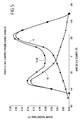
- FIG. 5 represents the profile of the axial magnetic field created in enclosure E respectively, by each of the magnetic rings 11, 12 with radial magnetization taken in isolation as well as by juxtaposition of these annular elements constituting the first magnetic means 1.
- the device then presents the configuration of an ECR source called "to magnetic mirror ".
- a single magnetic ring 11, 12 corresponds to a so-called “single gradient" source.
- the beam of ions extracted in a such a configuration can then be very wide and very intense, which turns out very useful for cleaning surfaces (pickling, etc.).
- the use of a single radial magnet ring 11, 12 with the second magnetic means 2 in the form of a magnet ring multipolar 21, corresponds to a multipolar source with gradient.
Landscapes
- Physics & Mathematics (AREA)
- Engineering & Computer Science (AREA)
- Plasma & Fusion (AREA)
- Chemical & Material Sciences (AREA)
- Analytical Chemistry (AREA)
- Spectroscopy & Molecular Physics (AREA)
- Optics & Photonics (AREA)
- Combustion & Propulsion (AREA)
- Electromagnetism (AREA)
- Plasma Technology (AREA)
Applications Claiming Priority (2)
| Application Number | Priority Date | Filing Date | Title |
|---|---|---|---|
| FR0108244 | 2001-06-22 | ||
| FR0108244A FR2826542B1 (fr) | 2001-06-22 | 2001-06-22 | Dispositif pour la production d'ions de charges positives variables et a resonnance cyclotronique |
Publications (1)
| Publication Number | Publication Date |
|---|---|
| EP1272015A1 true EP1272015A1 (de) | 2003-01-02 |
Family
ID=8864648
Family Applications (1)
| Application Number | Title | Priority Date | Filing Date |
|---|---|---|---|
| EP02291487A Withdrawn EP1272015A1 (de) | 2001-06-22 | 2002-06-14 | Zyklotronresonanzvorrichtung zur Erzeugung von Ionen mit variabler positiver Ladung |
Country Status (2)
| Country | Link |
|---|---|
| EP (1) | EP1272015A1 (de) |
| FR (1) | FR2826542B1 (de) |
Cited By (2)
| Publication number | Priority date | Publication date | Assignee | Title |
|---|---|---|---|---|
| WO2011001051A1 (fr) | 2009-06-29 | 2011-01-06 | Quertech Ingenierie | Système magnétique formant des surfaces iso modules fermées à partir de structures magnétiques de type «cusp» et sources d'ions de type rce mettant en oeuvre un tel système |
| ES2696227A1 (es) * | 2018-07-10 | 2019-01-14 | Centro De Investig Energeticas Medioambientales Y Tecnologicas Ciemat | Fuente de iones de radiofrecuencia de baja erosion |
Citations (6)
| Publication number | Priority date | Publication date | Assignee | Title |
|---|---|---|---|---|
| US4789809A (en) * | 1987-03-19 | 1988-12-06 | Potomac Photonics, Inc. | High frequency discharge apparatus with impedance matching |
| US5189446A (en) * | 1991-05-17 | 1993-02-23 | International Business Machines Corporation | Plasma wafer processing tool having closed electron cyclotron resonance |
| DE4136297A1 (de) * | 1991-11-04 | 1993-05-06 | Plasma Electronic Gmbh, 7024 Filderstadt, De | Vorrichtung zur lokalen erzeugung eines plasmas in einer behandlungskammer mittels mikrowellenanregung |
| US5344536A (en) * | 1991-12-03 | 1994-09-06 | Tokyo Ohka Kogyo Co., Ltd. | Method of and apparatus for processing a workpiece in plasma |
| JPH0831358A (ja) * | 1994-07-12 | 1996-02-02 | Nissin Electric Co Ltd | Ecrイオンラジカル源 |
| US5789322A (en) * | 1996-05-29 | 1998-08-04 | Applied Materials, Inc. | Low volume gas distribution assembly for a chemical downstream etch tool |
-
2001
- 2001-06-22 FR FR0108244A patent/FR2826542B1/fr not_active Expired - Fee Related
-
2002
- 2002-06-14 EP EP02291487A patent/EP1272015A1/de not_active Withdrawn
Patent Citations (6)
| Publication number | Priority date | Publication date | Assignee | Title |
|---|---|---|---|---|
| US4789809A (en) * | 1987-03-19 | 1988-12-06 | Potomac Photonics, Inc. | High frequency discharge apparatus with impedance matching |
| US5189446A (en) * | 1991-05-17 | 1993-02-23 | International Business Machines Corporation | Plasma wafer processing tool having closed electron cyclotron resonance |
| DE4136297A1 (de) * | 1991-11-04 | 1993-05-06 | Plasma Electronic Gmbh, 7024 Filderstadt, De | Vorrichtung zur lokalen erzeugung eines plasmas in einer behandlungskammer mittels mikrowellenanregung |
| US5344536A (en) * | 1991-12-03 | 1994-09-06 | Tokyo Ohka Kogyo Co., Ltd. | Method of and apparatus for processing a workpiece in plasma |
| JPH0831358A (ja) * | 1994-07-12 | 1996-02-02 | Nissin Electric Co Ltd | Ecrイオンラジカル源 |
| US5789322A (en) * | 1996-05-29 | 1998-08-04 | Applied Materials, Inc. | Low volume gas distribution assembly for a chemical downstream etch tool |
Non-Patent Citations (1)
| Title |
|---|
| PATENT ABSTRACTS OF JAPAN vol. 1996, no. 06 28 June 1996 (1996-06-28) * |
Cited By (4)
| Publication number | Priority date | Publication date | Assignee | Title |
|---|---|---|---|---|
| WO2011001051A1 (fr) | 2009-06-29 | 2011-01-06 | Quertech Ingenierie | Système magnétique formant des surfaces iso modules fermées à partir de structures magnétiques de type «cusp» et sources d'ions de type rce mettant en oeuvre un tel système |
| ES2696227A1 (es) * | 2018-07-10 | 2019-01-14 | Centro De Investig Energeticas Medioambientales Y Tecnologicas Ciemat | Fuente de iones de radiofrecuencia de baja erosion |
| WO2020012047A1 (es) * | 2018-07-10 | 2020-01-16 | Centro De Investigaciones Energéticas, Medioambientales Y Tecnológicas (Ciemat) | Fuente de iones interna para ciclotrones de baja erosión |
| US11497111B2 (en) | 2018-07-10 | 2022-11-08 | Centro De Investigaciones Energeticas, Medioambientales Y Technologicas (Ciemat) | Low-erosion internal ion source for cyclotrons |
Also Published As
| Publication number | Publication date |
|---|---|
| FR2826542A1 (fr) | 2002-12-27 |
| FR2826542B1 (fr) | 2003-09-26 |
Similar Documents
| Publication | Publication Date | Title |
|---|---|---|
| EP0238397B1 (de) | Elektronenzyklotronresonanz-Ionenquelle mit koaxialer Injektion elektromagnetischer Wellen | |
| EP1075168B1 (de) | Verfahren zur Erzeugung eines Grundplasmas, um ein gleichförmiges Plasma für eine Zieloberfläche zu erzeugen und Erzeugungsvorrichtung dafür | |
| FR2693770A1 (fr) | Moteur à plasma à dérive fermée d'électrons. | |
| FR2702119A1 (fr) | Dispositif d'excitation d'un plasma à la résonance cyclotronique électronique par l'intermédiaire d'un applicateur filaire d'un champ micro-onde et d'un champ magnétique statique. | |
| EP0711100A1 (de) | Plasmaerzeugungsvorrichtung, ermöglichend eine Trennung zwischen Mikrowellenübertragung und -absorptionszonen | |
| EP2873306B1 (de) | Koaxialer mikrowellenapplikator zur plasmaerzeugung | |
| EP1272015A1 (de) | Zyklotronresonanzvorrichtung zur Erzeugung von Ionen mit variabler positiver Ladung | |
| EP0722651B1 (de) | Vorrichtung und verfahren zur plasmaerzeugung durch verwendung von mikrowellen | |
| EP0037309B1 (de) | Wanderfeldröhre mit aus gekoppelten Hohlräumen bestehender Verzögerungsleitung und mit periodischer permanentmagnetischer Fokussierung und Verstärkereinheit mit einer solchen Röhre | |
| EP0499514B1 (de) | Modenwandler und Leistungsteiler-Einrichtung für eine Mikrowellenröhre, und Mikrowellenröhre mit einer solchen Einrichtung | |
| EP0946961B1 (de) | Magnetische vorrichtung, insbesondere fuer elektronzyklotronresonanzionenquellen, die die erzeugung geschlossener oberflaechen mit konstanter magnetfeldstaerke b und beliebiger groesse ermoeglichen | |
| EP0532411B1 (de) | Elektronzyklotronresonanz-Ionenquelle mit koaxialer Zuführung elektromagnetischer Wellen | |
| EP0527082B1 (de) | Elektroncyclotionresonanz-Ionenquelle vom Wellenleiter-Typ zur Erzeugung mehrfachgeladenen Ionen | |
| FR2724264A1 (fr) | Antenne cylindrique utilisable pour generer un plasma dans les conditions de resonance cyclotronique electronique | |
| FR2613534A1 (fr) | Gyrotron | |
| WO2014184357A1 (fr) | Générateur de plasma étendu comprenant des générateurs élémentaires intégrés | |
| EP0813223A1 (de) | Magnetfelderzeugungsvorrichtung und ECR Ionenquelle dafür | |
| FR2833748A1 (fr) | Tube electronique a collecteur simplifie | |
| FR2969372A1 (fr) | Dispositif d’ionisation a la resonance cyclotron electronique | |
| FR2925758A1 (fr) | Tube electronique a cavite resonnante | |
| JP2020506526A (ja) | プラズマ源 | |
| JPH04184899A (ja) | プラズマ発生装置 | |
| FR2467480A1 (fr) | Appareil a hyperfrequences du type magnetron | |
| WO1999062307A1 (fr) | Dispositif destine a creer un champ magnetique a l'interieur d'une enceinte | |
| FR2882191A1 (fr) | Montage de reglage d'accord de frequence pour tube a sortie inductive |
Legal Events
| Date | Code | Title | Description |
|---|---|---|---|
| PUAI | Public reference made under article 153(3) epc to a published international application that has entered the european phase |
Free format text: ORIGINAL CODE: 0009012 |
|
| AK | Designated contracting states |
Kind code of ref document: A1 Designated state(s): AT BE CH CY DE DK ES FI FR GB GR IE IT LI LU MC NL PT SE TR |
|
| AX | Request for extension of the european patent |
Free format text: AL;LT;LV;MK;RO;SI |
|
| 17P | Request for examination filed |
Effective date: 20030219 |
|
| AKX | Designation fees paid |
Designated state(s): BE DE GB IT NL SE |
|
| STAA | Information on the status of an ep patent application or granted ep patent |
Free format text: STATUS: THE APPLICATION IS DEEMED TO BE WITHDRAWN |
|
| 18D | Application deemed to be withdrawn |
Effective date: 20070101 |