EP1272409B1 - Appareil de manipulation servant a transferer des pieces - Google Patents
Appareil de manipulation servant a transferer des pieces Download PDFInfo
- Publication number
- EP1272409B1 EP1272409B1 EP01916971A EP01916971A EP1272409B1 EP 1272409 B1 EP1272409 B1 EP 1272409B1 EP 01916971 A EP01916971 A EP 01916971A EP 01916971 A EP01916971 A EP 01916971A EP 1272409 B1 EP1272409 B1 EP 1272409B1
- Authority
- EP
- European Patent Office
- Prior art keywords
- path
- gripper carrier
- handling device
- handling
- movement
- Prior art date
- Legal status (The legal status is an assumption and is not a legal conclusion. Google has not performed a legal analysis and makes no representation as to the accuracy of the status listed.)
- Expired - Lifetime
Links
Images

Classifications
-
- B—PERFORMING OPERATIONS; TRANSPORTING
- B65—CONVEYING; PACKING; STORING; HANDLING THIN OR FILAMENTARY MATERIAL
- B65G—TRANSPORT OR STORAGE DEVICES, e.g. CONVEYORS FOR LOADING OR TIPPING, SHOP CONVEYOR SYSTEMS OR PNEUMATIC TUBE CONVEYORS
- B65G47/00—Article or material-handling devices associated with conveyors; Methods employing such devices
- B65G47/74—Feeding, transfer, or discharging devices of particular kinds or types
- B65G47/90—Devices for picking-up and depositing articles or materials
-
- B—PERFORMING OPERATIONS; TRANSPORTING
- B23—MACHINE TOOLS; METAL-WORKING NOT OTHERWISE PROVIDED FOR
- B23Q—DETAILS, COMPONENTS, OR ACCESSORIES FOR MACHINE TOOLS, e.g. ARRANGEMENTS FOR COPYING OR CONTROLLING; MACHINE TOOLS IN GENERAL CHARACTERISED BY THE CONSTRUCTION OF PARTICULAR DETAILS OR COMPONENTS; COMBINATIONS OR ASSOCIATIONS OF METAL-WORKING MACHINES, NOT DIRECTED TO A PARTICULAR RESULT
- B23Q5/00—Driving or feeding mechanisms; Control arrangements therefor
- B23Q5/22—Feeding members carrying tools or work
- B23Q5/34—Feeding other members supporting tools or work, e.g. saddles, tool-slides, through mechanical transmission
- B23Q5/341—Feeding other members supporting tools or work, e.g. saddles, tool-slides, through mechanical transmission cam-operated
-
- B—PERFORMING OPERATIONS; TRANSPORTING
- B25—HAND TOOLS; PORTABLE POWER-DRIVEN TOOLS; MANIPULATORS
- B25J—MANIPULATORS; CHAMBERS PROVIDED WITH MANIPULATION DEVICES
- B25J9/00—Program-controlled manipulators
- B25J9/10—Program-controlled manipulators characterised by positioning means for manipulator elements
- B25J9/109—Program-controlled manipulators characterised by positioning means for manipulator elements comprising mechanical programming means, e.g. cams
-
- B—PERFORMING OPERATIONS; TRANSPORTING
- B65—CONVEYING; PACKING; STORING; HANDLING THIN OR FILAMENTARY MATERIAL
- B65G—TRANSPORT OR STORAGE DEVICES, e.g. CONVEYORS FOR LOADING OR TIPPING, SHOP CONVEYOR SYSTEMS OR PNEUMATIC TUBE CONVEYORS
- B65G47/00—Article or material-handling devices associated with conveyors; Methods employing such devices
- B65G47/74—Feeding, transfer, or discharging devices of particular kinds or types
- B65G47/90—Devices for picking-up and depositing articles or materials
- B65G47/902—Devices for picking-up and depositing articles or materials provided with drive systems incorporating rotary and rectilinear movements
-
- B—PERFORMING OPERATIONS; TRANSPORTING
- B23—MACHINE TOOLS; METAL-WORKING NOT OTHERWISE PROVIDED FOR
- B23Q—DETAILS, COMPONENTS, OR ACCESSORIES FOR MACHINE TOOLS, e.g. ARRANGEMENTS FOR COPYING OR CONTROLLING; MACHINE TOOLS IN GENERAL CHARACTERISED BY THE CONSTRUCTION OF PARTICULAR DETAILS OR COMPONENTS; COMBINATIONS OR ASSOCIATIONS OF METAL-WORKING MACHINES, NOT DIRECTED TO A PARTICULAR RESULT
- B23Q2210/00—Machine tools incorporating a specific component
- B23Q2210/006—Curved guiding rails
Definitions
- the invention relates to a handling device for repositioning of parts, with at least one through a drive device to an oscillating swiveling movement Swivel axis drivable swivel arm, which during the swivel movement such as one for carrying a gripper Gripper carrier acts that this without changing its spatial orientation along a given handling path is shifted, the gripper carrier with a Curve follower communicates with one Pieces extending far along the circumference of the pivot axis and defining the desired course of the handling path Path specification curve is engaged, the gripper carrier to realize one at least partially by one Circular path deviating handling path relative to the pivot axis mounted movably with respect to this radial direction is so that it is one of the orbital movement about the pivot axis can perform superimposed radial movement, and wherein the Gripper carrier to fix its spatial orientation by a guide device provided in addition to the swivel arm is supported and guided.
- a handling device is known, for example, from DE 296 18 418 U1. It is used to reposition parts which are recorded in a first position and become a second position where they are placed.
- the gripper carrier is in the handling device of DE 296 18 418 U1 Part of a parallelogram system containing two swivel arms, the handling path he has passed through is a pure circular path.
- a non-circular handling path for example an essentially U-shaped handling path with mutually parallel linear end sections, which enables components to be positioned at the beginning and end of the repositioning process to move a bit linearly, for example assigned to screws or short shaft pieces Remove the brackets and insert them in the provided recesses.
- Embodiments are already in DE 296 18 418 U1 described, in which the gripper along a non-circular Can shift handling path. However this is associated with a change in spatial orientation of the gripper or gripper carrier, which is the area of application again severely restricted.
- DE 36 03 650 C2 has already been used as a transfer device designated handling device proposed with the a gripper along a non-circular handling path with mutually parallel web end sections under constant Shifting its spatial orientation leaves.
- the drive concept used here is however relatively complex and requires a large construction volume, by requiring two fluid operated cylinders to realize the desired path.
- the gripper carrier via a linear guide rail on a guide carriage linearly displaceable in a first direction of movement is guided, the guide carriage in turn on a linear guide fixed in relation to the swivel axis in a second perpendicular to the first direction of movement Direction of movement is adjustable.
- the handling device could also be under Use of several and in particular two in a joint parallelogram realize integrated swivel arms.
- the rule is an embodiment with only one Swivel arm less expensive and requires less manufacturing effort.
- an additional is recommended Support and guidance of the gripper carrier on one in addition to the guide device provided for the swivel arm, which is also able to achieve the desired spatial orientation of the gripper carrier.
- the gripper carrier is guided very precisely, if it attacks the swivel arm on the one hand and the other engages with the path specification curve via the curve follower stands, provided with a linear guide rail is on a guide carriage in a first direction of movement is linearly guided, which in turn on a linear guide in a direction of the first movement right-angled second direction of movement adjustable is guided, being that of the two directions of movement spanned plane of movement perpendicular to the swivel axis of the swivel arm.
- the kinematic design of the by the swivel arm and the Curve intervention realized kinematics is expedient taken in such a way that the direction of the path specification curve corresponds to that of the handling path, so that a results in a direct dependency, which is the production of the path specification curve considerably simplified.
- the handling device has a path specification curve essentially U-shaped course and two to each other parallel linear curve end sections, it is advantageous if the swivel axis is at least one or only one Swivel arm in the middle between the linear curve end sections is placed. In this way, it results particularly compact dimensions.
- the gripper carrier is expedient with respect to the Radially adjustable swivel axis on at least one swivel arm stored and is at the same time in a take-away operation with the swivel arm.
- the gripper carrier can with a preferably roll-like drivers in a respect engage the radially aligned slot, to implement the carry-on intervention.
- the preferred can also be roller-like curve followers placed in a coaxial arrangement with the driver be, which in turn is particularly compact dimensions allows.
- the additional guide device can be designed in this way be that the gripper carrier only two degrees of freedom of movement perpendicular to one another enables the desired in one level To be able to go through the handling path.
- the handling device variably, is it conveniently equipped with slings that a variable specification of the length of the gripper carrier enable continuous handling path and are expediently arranged so that they with the Work the gripper carrier together.
- Can also Shock absorbing means may be provided which the ends of the Gripper carrier assigned to continuous handling path are to dampened braking of the gripper carrier when To enable reaching the respective end position.
- the Path specification curve is part of several, for example plate-shaped curve bearer is, at least are partially adjustable relative to each other to the To influence the course of the path specification curve.
- the length can be at least one Section of the curve vary, for example for adjustment to the length of the Distance between the start and end position of a repositioning part.
- the at least one swivel arm expediently comes in fluid-operated rotary actuator for use as an immediate Part of the handling device is executed.
- Fasteners are expediently on the gripper carrier provided that allow a releasable fixation of a gripper, so that if necessary while leaving the gripper carrier a simple gripper exchange can be made.
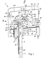
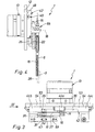
- That generally designated by reference number 1 in the drawing Handling device enables sequential repositioning parts of any kind, especially small parts such as screws, bolts or other parts with predominant Longitudinal extent. There is one in the drawing part to be repositioned indicated by dash-dotted lines at 2.
- the handling device 1 is designed so that the part 2 during a repositioning process between two spaced End positions 3, 4 is displaceable, the thereby by him traversed trajectory also the course of a corresponds to the handling path 5 indicated by dash-dotted lines, which a driven gripper carrier 6 passes through with a for releasably holding the part to be repositioned Gripper 7 is of a suitable design.
- the gripper 7 can be, for example, a pair of pliers Act gripper, the swiveling gripper jaws 8, which is electrical or preferably by fluid power Have pressed to hold part 2 as needed or let go.
- Other possible embodiments for the gripper 7 would be, for example, suction grippers or magnetic grippers, the part to be handled by vacuum or can hold by magnetic force.
- the handling device 1 preferably contains a base plate-shaped support body 12, in particular on the back formed by a single fluid-operated rotary drive Drive device 13 is attached.
- a drive shaft 14 of the drive device 13 passes through the support body 12 and carries one in the area of the front of the support body 12 radially projecting swivel arm 15.
- the gripper carrier 6 is in the embodiment of one elongated, rod or strip-shaped component formed and with a linear one extending in its longitudinal direction Guide rail 18 equipped.
- the latter can be used as a separate one Part or as an integral part of the gripper carrier 6 be executed.
- the guide rail 18 extends in one to the pivot axis 16 at right angles.
- the gripper carrier 6 is on one via the guide rail 18 Guide carriage 22 in a indicated by a double arrow first direction of movement 23 guided linearly.
- the Guide carriage 22 in turn is on a linear guide 25 in a direction perpendicular to the first direction of movement 23 second movement direction 24 guided adjustable.
- the linear guide 25 is in the embodiment of a guide rail formed on the front of the support body 12 is attached and rider-like from the guide carriage 22 is attacked.
- the gripper carrier 6 stands with that in the embodiment single swivel arm 15 in driving engagement, so that he the pivoting movement of the pivot arm 15 in a predetermined Way is moved.
- the carry-on intervention is designed that the gripper carrier 6 with respect to the pivot axis 16 is mounted radially adjustable on the swivel arm. In the embodiment this is achieved by using the swivel arm 15 an extending in its longitudinal direction, with respect the pivot axis 16 radially extending slot 27 is provided is in which a driver arranged on the gripper carrier 6 28 engages.
- the driver 28 is in the embodiment a roller body rotatably mounted on the gripper carrier 6, wherein the axis of rotation 31 runs parallel to the pivot axis 16.
- the swivel arm 15 performs a swivel movement, it acts the flank of the elongated hole currently oriented in the swivel direction 27 on the driver 28 and takes the gripper carrier 6 with, so that this is indicated by a double arrow Orbital movement 32 with respect to the pivot axis 16 executes.
- the guide device 21 always ensures that the gripper carrier 6 is supported and guided that it has its spatial orientation regardless of the current one Maintains position. He changes his position in the Space, but only as part of a relocation and without change its angular orientation. As a consequence, that the gripping section engaging on part 2 to be handled 34 of the gripper 7 always points in the same direction when Embodiment vertically downwards.
- the course of the path specification curve 36 chosen so that the gripper carrier 6 and thus also a handling path 5 passed through by the gripper 7 during operation essentially U-shaped course with two parallel to each other linear path end portions 37a, 37b. by virtue of the one taken in the exemplary embodiment and explained above
- the courses correspond to the kinematic design the path specification curve 36 and the handling path 5. This facilitates production because of the course of the path specification curve 36 specify the course of the handling path 5 1: 1 can be.
- the path specification curve 36 an essentially U-shaped course with two to one another parallel linear curve end portions 38a, 38b, where expediently the ends of the curve end sections 38a, 38b point in the same direction as the gripping section 34, here as vertical down.
- the path specification curve 36 and consequently the handling path 5 thus has a U-like Course with the U opening pointing downwards.
- the pivot axis 16 of the preferably single pivot arm 15 is preferably in the middle of the embodiment between the two curve end sections 38a, 38b of the path specification curve 36. This enables particularly compact dimensions of the handling device in both the width and height directions.
- the gripper carrier 6 thus engages on the one hand on the swivel arm 15 and is also on the curve follower 35 with the path specification curve 36 in leadership engagement.
- the path specification curve 36 is in the embodiment of the flanks one of the desired Defines the curve of the following longitudinal slot 39, which is formed on a curve carrier device 42 is that in the embodiment at the front of the Support body 12 is attached.
- the curve follower 35 protrudes from forward into the longitudinal slot 39, the back through the support body 12 or through a corresponding wall of the curve carrier device 42 can be closed, so that a groove-like structure results.
- the curve follower 35 is in the embodiment of one how the driver formed 28 roller-bearing roller bodies, which engages in the longitudinal slot 39 with slight play, so that it can roll on its slot flanks.
- the curve follower 35 is expediently coaxial with the driver 28 arranged so that coinciding axes of rotation 31 result. Both components can work together on one Gripper carrier 6 fixed bearing axis 43 may be mounted. It is expediently provided that the elongated Body-formed gripper carrier 6 via the swivel arm 15 reaches away, which thus between the gripper carrier 6 and the support body 12 is located, the bearing axis 43 the Elongated hole 27 passes through and in the area of the elongated hole 27 Carrier 28 and below this carries the curve follower 35.
- the curve carrier device 42 is in the embodiment from several plate-like designed curve carriers 44, which is in a plane parallel to the plane of movement 26 the front of the support body 12 are attached.
- This Curve carriers 44 are at least partially relative in this level adjustable to each other to the course of the path specification curve 36 to be able to influence.
- variable in length Designated curve section 45 In the embodiment there is doing the advantageous way of determining the length of a particular Section of the curve, hereinafter referred to as variable in length Designated curve section 45 to vary.
- variable-length curve section 45 the connecting section extending transversely between the U-legs, a linear in the embodiment Has course.
- the U-shaped shape is thus made up of the two mutually parallel linear curve end sections 38a, 38b, the intermediate length variable linear Curve section 45 and each an arcuate transition section 46a, 46b between the variable-length curve section 45 and a respective curve end section 38a, 38b together.
- the curve carriers 44 are designed so that the curve specification curve 36 defining flanks of the longitudinal slot 39 overlap in the longitudinal direction of the curve, the degree of overlap depends on the current setting.
- central curve bearer 44a provided, which is immovably attached to the support body 12 and is at least a partial length of the length variable Defined curve section 45.
- This central cam bearer 44a is on one side flanked outer curve carriers 44b, 44c, on which the rest Curve sections are provided and in the longitudinal direction of the variable-length curve section 45 relative to the support body 12 adjustable and fixable in the set position are. This varies depending on the setting wide overlap of adjacent slit flank areas in overlap areas 47 marked by arrows.
- the two movable outer cam carrier 44 on one on the support body 12 fixed and parallel to the variable-length curve section 45 extending guide rail 48 and cooperate each with an adjusting screw supported on the support body 12 49 or another adjustment mechanism that a stepless position adjustment enables.
- the respectively set position is in the embodiment fixed by one or more fastening screws 53, which reach through the support body 12 from the rear and in the relevant outer curve carrier 44b, 44c are screwed in.
- the reach area of the fastening screws 53 in the support body 12 is in each case an elongated hole 54 formed so that the mounting screws 53 after the Loosen together with the movable cam 44b, 44c shifted can be put to the new position again tighten.
- Linear guide 25 is in the embodiment in one upstream of the ends of the two curve end sections 38a, 38b Area and extends transversely to these curve end sections 38a, 38b parallel to the variable-length curve section 45.
- the linear guide expediently extends 25 on the same level as the curve support facility 42nd
- the handling device 1 is preferably also with slings 55 equipped with a variable specification of the length of the enable handling path 5 to be traversed by the gripper carrier 6.
- each curve end section 38a, 38b assigned a stop unit 56a, 56b, with the gripper carrier 6 when approaching the desired one End position can work together.
- the gripper carrier 6 is in the exemplary embodiment with counter-stop units 57a, 57b equipped, which expediently on one Cross member 59 of the gripper carrier 6 are attached and each for cooperation with one of the stop units 56a, 56b are provided.
- Suitable setting options for example Adjustment thread, allow a continuously variable Position specification.
- the handling device 1 is also preferably with shock absorbing means 58 equipped like the sling 55 the ends of the handling path to be traversed by the gripper carrier 6 5 are assigned and cooperate with the gripper carrier 6 can to the final impact when reaching the dampen by the sling predetermined end positions.
- the shock absorbing means 58 can be simple buffering means be, but are preferably from hydraulic shock absorbers educated.
- each stop unit 56a, 56b designed as a structural unit with a shock absorber.
- the handling device is also under simultaneous Use of several and in particular two swivel arms 15 could be realized, a design with only one swivel arm 15 usually preferred, because it is manufacturing technology Advantages and compact dimensions have cost-effective production.
- Suitable fasteners are indicated at 60.
Landscapes
- Engineering & Computer Science (AREA)
- Mechanical Engineering (AREA)
- Robotics (AREA)
- Manipulator (AREA)
- Specific Conveyance Elements (AREA)
Claims (16)
- Appareil de manipulation pour repositionner des pièces, comportant au moins un bras pivotant (15) pouvant être entraíné par un dispositif d'entraínement (13) en un mouvement de pivotement oscillant autour d'un axe de pivotement (16), lequel bras pivotant agit, lors du mouvement de pivotement, sur un porte-pince (6) servant à supporter une pince (7), pendant le mouvement de pivotement, de manière que celui-ci soit déplacé, sans modification de son orientation spatiale, le long d'une trajectoire de manipulation (5) prédéfinie, le porte-pince (6) étant en liaison avec un suiveur de courbe (35) qui est en prise avec une courbe de sélection de trajectoire (36) s'étendant sur une certaine distance le long de la circonférence de l'axe de pivotement (16) et définissant l'allure souhaitée de la trajectoire de manipulation (5), tandis que pour réaliser une trajectoire de manipulation (5) s'écartant au moins en partie d'une trajectoire circulaire par rapport à l'axe de pivotement (16), le porte-pince (6) est monté déplaçable dans une direction radiale par rapport à celui-ci, de sorte qu'il peut exécuter un mouvement radial (33) superposé au mouvement de rotation (32) autour de l'axe de pivotement (16), et, pour fixer son orientation spatiale, le porte-pince (6) est soutenu et guidé par un dispositif de guidage (21) prévu en supplément au bras pivotant (15), caractérisé en ce que le porte-pince (6) est guidé, par un rail de guidage (18) linéaire, sur un chariot de guidage (22) de manière à pouvoir coulisser linéairement dans une première direction de déplacement (23), le chariot de guidage (22) étant guidé réglable de son côté sur un guide linéaire (25) fixe par rapport à l'axe de pivotement (16), dans une deuxième direction de déplacement (24) perpendiculaire à la première direction de déplacement (23).
- Appareil de manipulation selon la revendication 1, caractérisé en ce que l'allure de la courbe de sélection de trajectoire (36) est réalisée de manière que la trajectoire de manipulation (5), suivie pendant le fonctionnement par le porte-pince (6), présente un parcours sensiblement en U avec deux tronçons terminaux de trajectoire (37a, 37b) linéaires, parallèles l'un à l'autre.
- Appareil de manipulation selon la revendication 1 ou 2, caractérisé en ce que la conception cinématique est telle que l'allure de la direction de la courbe de sélection de trajectoire (36) corresponde à celle de la trajectoire de manipulation (5).
- Appareil de manipulation selon la revendication 3, en combinaison avec la revendication 2, caractérisé en ce que la courbe de sélection de trajectoire (36) présente un parcours sensiblement en U avec deux tronçons terminaux de courbe (38a, 38b) linéaires, parallèles l'un à l'autre, l'axe de pivotement (16) d'au moins un bras pivotant (15) étant placé de préférence au milieu entre les tronçons terminaux de courbe (38a, 38b).
- Appareil de manipulation selon l'une des revendications 1 à 4, caractérisé en ce que le porte-pince (6) est monté sur au moins un bras pivotant (15), réglable radialement par rapport à l'axe de pivotement (16), et est en même temps avantageusement en engagement d'entraínement avec le bras pivotant (15).
- Appareil de manipulation selon la revendication 5, caractérisé en ce qu'un entraíneur (28), relié au porte-pince (6) et réalisé de préférence à la manière d'un rouleau, s'engage dans un trou oblong (27), orienté radialement par rapport à l'axe de pivotement (16), du bras pivotant (15), pour provoquer un engagement d'entraínement.
- Appareil de manipulation selon la revendication 6, caractérisé en ce que le suiveur de courbe (35), réalisé de préférence à la manière d'un rouleau, est disposé coaxialement à l'entraíneur (28).
- Appareil de manipulation selon l'une des revendications 1 à 7, caractérisé en ce que le porte-pince (6) agit uniquement sur un seul bras pivotant (15).
- Appareil de manipulation selon l'une des revendications 1 à 8, caractérisé en ce que le dispositif de guidage (21) est réalisé de manière à permettre au porte-pince (6) exclusivement deux degrés de liberté de mouvement perpendiculaires l'un à l'autre.
- Appareil de manipulation selon l'une des revendications 1 à 9, caractérisé en ce que le guide linéaire (25), en combinaison avec une courbe de sélection de trajectoire (36) présentant un parcours en U, s'étend, dans une zone située devant les tronçons terminaux de courbe (38a, 38b), transversalement à ces tronçons terminaux de courbe (38a, 38b).
- Appareil de manipulation selon l'une des revendications 1 à 10, caractérisé par des moyens de butée (56), servant à la sélection variable de la longueur de la trajectoire de manipulation (5) que doit suivre le porte-pince (6), lesquels moyens coopèrent avantageusement avec le porte-pince (6).
- Appareil de manipulation selon l'une des revendications 1 à 11, caractérisé par des moyens d'amortissement de chocs (58) qui sont associés aux extrémités de la trajectoire de manipulation (5) que doit suivre le porte-pince (6), et qui coopèrent avec le porte-pince (6).
- Appareil de manipulation selon l'une des revendications 1 à 12, caractérisé en ce que la courbe de sélection de trajectoire (36) fait partie intégrante de plusieurs porte-courbes (44) qui, pour influencer l'allure de la courbe de sélection de trajectoire (36), sont réglables au moins en partie les uns par rapport aux autres.
- Appareil de manipulation selon la revendication 13, caractérisé en ce que les porte-courbes (44) sont disposés sur un corps de support (12) de préférence de type plaque, sur lequel est avantageusement prévu aussi le dispositif de guidage (21), éventuellement prévu, pour le porte-pince (6).
- Appareil de manipulation selon l'une des revendications 1 à 14, caractérisé en ce que le dispositif d'entraínement (13) est constitué par un dispositif d'entraínement en rotation électrique ou actionné par un fluide.
- Appareil de manipulation selon l'une des revendications 1 à 15, caractérisé par une pince (7) fixée de manière séparable sur le porte-pince (6).
Applications Claiming Priority (3)
| Application Number | Priority Date | Filing Date | Title |
|---|---|---|---|
| DE20004746U | 2000-03-15 | ||
| DE20004746U DE20004746U1 (de) | 2000-03-15 | 2000-03-15 | Handhabungsgerät zum Umpositionieren von Teilen |
| PCT/EP2001/001069 WO2001068490A1 (fr) | 2000-03-15 | 2001-02-01 | Appareil de manipulation servant a transferer des pieces |
Publications (2)
| Publication Number | Publication Date |
|---|---|
| EP1272409A1 EP1272409A1 (fr) | 2003-01-08 |
| EP1272409B1 true EP1272409B1 (fr) | 2004-06-16 |
Family
ID=7938764
Family Applications (1)
| Application Number | Title | Priority Date | Filing Date |
|---|---|---|---|
| EP01916971A Expired - Lifetime EP1272409B1 (fr) | 2000-03-15 | 2001-02-01 | Appareil de manipulation servant a transferer des pieces |
Country Status (6)
| Country | Link |
|---|---|
| US (1) | US6851917B2 (fr) |
| EP (1) | EP1272409B1 (fr) |
| JP (1) | JP2003526530A (fr) |
| KR (1) | KR20020084181A (fr) |
| DE (2) | DE20004746U1 (fr) |
| WO (1) | WO2001068490A1 (fr) |
Cited By (1)
| Publication number | Priority date | Publication date | Assignee | Title |
|---|---|---|---|---|
| DE102007014130A1 (de) | 2007-03-23 | 2008-09-25 | Festo Ag & Co. Kg | Handhabungsgerät |
Families Citing this family (44)
| Publication number | Priority date | Publication date | Assignee | Title |
|---|---|---|---|---|
| DE20004746U1 (de) * | 2000-03-15 | 2000-08-10 | Festo AG & Co, 73734 Esslingen | Handhabungsgerät zum Umpositionieren von Teilen |
| FR2833201B1 (fr) * | 2001-12-12 | 2004-03-12 | Dubuit Mach | Dispositif de transfert d'objets industriels entre deux positions |
| DE10314818B4 (de) * | 2003-04-01 | 2006-05-04 | Festo Ag & Co. | Handhabungsgerät zum Umpositionieren von Teilen |
| DE10348078A1 (de) * | 2003-10-13 | 2005-05-12 | Suhling Technik Niederlassung | Vorrichtung zum Erzeugen einer zusammengesetzten Linear- und Querbewegung |
| DE50306864D1 (de) | 2003-12-02 | 2007-05-03 | Festo Ag & Co | Handhabungsgerät zum Umpositionieren von Teilen |
| DE102004004896B4 (de) * | 2004-01-30 | 2006-06-14 | Festo Ag & Co. | Handhabungsgerät zum Umpositionieren von Teilen |
| FR2872725B1 (fr) * | 2004-07-08 | 2007-09-28 | Comau Systemes France Sa | Dispositif simplifie de transfert rotatif |
| US7175381B2 (en) * | 2004-11-23 | 2007-02-13 | Scriptpro Llc | Robotic arm for use with pharmaceutical unit of use transport and storage system |
| DE102005015949B4 (de) * | 2005-04-07 | 2007-01-25 | Festo Ag & Co. | Mit Druckluft betriebene Arbeitsvorrichtung |
| JP5171119B2 (ja) * | 2006-06-20 | 2013-03-27 | 有限会社メック | 往復運動機構及びピックアンドプレイス装置 |
| KR101023521B1 (ko) * | 2008-12-31 | 2011-03-21 | 장오기계 주식회사 | 조립부품 회전 공급장치 |
| DE102009006044B4 (de) | 2009-01-24 | 2016-09-29 | Hans-Erich Maul | Handhabungsmodule |
| JP5467435B2 (ja) * | 2010-03-01 | 2014-04-09 | 株式会社マシンエンジニアリング | ピックアンドプレース装置 |
| DE102010029809B4 (de) | 2010-06-08 | 2012-04-19 | Schunk Gmbh & Co. Kg Spann- Und Greiftechnik | Handhabungseinheit zum Umsetzen von Teilen und Verfahren hierfür |
| DE102010029810B4 (de) | 2010-06-08 | 2012-10-25 | Schunk Gmbh & Co. Kg Spann- Und Greiftechnik | Handhabungseinheit zum Umsetzen von Teilen |
| ITMI20130725A1 (it) * | 2013-05-03 | 2014-11-04 | Cosberg Spa | Manipolatore per il prelievo e posizionamento di pezzi |
| ITMI20130726A1 (it) * | 2013-05-03 | 2014-11-04 | Cosberg Spa | Manipolatore per il prelievo e posizionamento di pezzi |
| CN103640894B (zh) * | 2013-12-04 | 2015-12-30 | 天津亿鑫通科技股份有限公司 | 精密往复移送装置 |
| JP2015128806A (ja) * | 2014-01-07 | 2015-07-16 | 株式会社デンソー | 搬送装置 |
| CN108032297A (zh) * | 2016-01-28 | 2018-05-15 | 林月洪 | 凸轮机械手 |
| CN107838907A (zh) * | 2016-01-30 | 2018-03-27 | 林月洪 | 联动式机器人手臂 |
| CN106006013A (zh) * | 2016-07-20 | 2016-10-12 | 苏州凡特斯测控科技有限公司 | 一种回转取料机构 |
| CN106185312A (zh) * | 2016-08-28 | 2016-12-07 | 上海贝特威自动化科技有限公司 | 一种翅片搬运机构 |
| CN106586530B (zh) * | 2016-11-30 | 2019-06-18 | 惠州金源精密自动化设备有限公司 | 顶盖上料装置 |
| CN106531507A (zh) * | 2016-12-14 | 2017-03-22 | 常州赛凯电器设备有限公司 | 一种用于热保护器感温元件的自动取件装置 |
| JP2018131224A (ja) * | 2017-02-14 | 2018-08-23 | いすゞ自動車株式会社 | マニピュレータ |
| JP6900698B2 (ja) * | 2017-02-14 | 2021-07-07 | いすゞ自動車株式会社 | マニピュレータ |
| CN107399604B (zh) * | 2017-08-23 | 2023-05-05 | 东莞科升自动化科技有限公司 | 送料装置 |
| CN108298304A (zh) * | 2017-12-29 | 2018-07-20 | 杭州高品自动化设备有限公司 | 一种摆臂件 |
| DE102018216393B4 (de) * | 2018-09-26 | 2022-04-07 | Festo Se & Co. Kg | Handhabungsvorrichtung zum Umpositionieren von Objekten |
| CN109835525A (zh) * | 2019-03-22 | 2019-06-04 | 浙江快利电子有限公司 | 一种连接器包装机的移料装置 |
| CN110155712A (zh) * | 2019-05-20 | 2019-08-23 | 苏州富强科技有限公司 | 一种同步转移机构 |
| CN110092191A (zh) * | 2019-05-20 | 2019-08-06 | 苏州富强科技有限公司 | 一种取料转移机构 |
| CN110937393A (zh) * | 2019-12-09 | 2020-03-31 | 珠海市梅木自动化科技有限公司 | 一种上下料装置 |
| CN110871998A (zh) * | 2019-12-18 | 2020-03-10 | 深圳市泽宇智能工业科技有限公司 | 一种单电机驱动的快速平移侧向取料机构 |
| CN111115233A (zh) * | 2019-12-31 | 2020-05-08 | 昆山博思达自动化设备科技有限公司 | 一种简易的缩小型超高速无损搬运机构 |
| CN111285098B (zh) * | 2020-03-03 | 2022-02-11 | 武汉轻工大学 | 盒体夹取装置 |
| CN111959866A (zh) * | 2020-08-20 | 2020-11-20 | 陈爱平 | 包装袋手柄抓放装置 |
| CN112296980A (zh) * | 2020-11-19 | 2021-02-02 | 东莞市禹瑞机电设备有限公司 | 一种ppu高速拾放移动机械手 |
| CN113753572A (zh) * | 2021-08-16 | 2021-12-07 | 俐玛精密测量技术(苏州)有限公司 | 凸轮搬运机构 |
| JP7818773B2 (ja) * | 2022-04-14 | 2026-02-24 | 株式会社マルセン | ピックアンドプレース装置 |
| CN115837674B (zh) * | 2022-12-16 | 2024-08-23 | 温州市日康机械科技厂 | 一种ppu机械手 |
| CN116532374B (zh) * | 2023-07-07 | 2023-10-17 | 珠海诚锋电子科技有限公司 | 一种全自动半导体检测设备 |
| CN119637481B (zh) * | 2024-12-16 | 2025-11-18 | 福建欧中电子有限公司 | 一种物料取放装置 |
Family Cites Families (10)
| Publication number | Priority date | Publication date | Assignee | Title |
|---|---|---|---|---|
| DD37169A (fr) | ||||
| US4289040A (en) * | 1979-08-27 | 1981-09-15 | Kinematics, Inc. | Linear motion device |
| SE419958B (sv) * | 1979-12-28 | 1981-09-07 | Volvo Ab | Rorelsemekanism for en retlinjig rorelse med i endarna anslutande vinkelreta rorelsedelar |
| DE3603650A1 (de) | 1986-02-06 | 1987-08-13 | Festo Kg | Positioniervorrichtung |
| US4740134A (en) * | 1986-10-03 | 1988-04-26 | Dixon Automatic Tool, Inc. | Pick and place machine |
| DE3702108C2 (de) | 1987-01-24 | 1994-06-01 | Laepple August Gmbh & Co | Motorgetriebene Vorrichtung zum Umsetzen von Werkstücken |
| DE9105666U1 (de) | 1991-05-07 | 1991-07-11 | Ingun Elektronik GmbH, 7312 Kirchheim | Stempelgerät mit elektromotorischem Antrieb |
| US5536136A (en) * | 1994-02-03 | 1996-07-16 | Utica Enterprises, Inc. | Mechanical loader |
| DE29618418U1 (de) | 1996-10-22 | 1997-01-16 | QUINTEST Elektronik GmbH, 73230 Kirchheim | Gerät zum Aufnehmen und Absetzen von Teilen |
| DE20004746U1 (de) * | 2000-03-15 | 2000-08-10 | Festo AG & Co, 73734 Esslingen | Handhabungsgerät zum Umpositionieren von Teilen |
-
2000
- 2000-03-15 DE DE20004746U patent/DE20004746U1/de not_active Expired - Lifetime
-
2001
- 2001-02-01 DE DE50102601T patent/DE50102601D1/de not_active Expired - Lifetime
- 2001-02-01 JP JP2001567004A patent/JP2003526530A/ja active Pending
- 2001-02-01 KR KR1020027011951A patent/KR20020084181A/ko not_active Withdrawn
- 2001-02-01 EP EP01916971A patent/EP1272409B1/fr not_active Expired - Lifetime
- 2001-02-01 WO PCT/EP2001/001069 patent/WO2001068490A1/fr not_active Ceased
- 2001-02-01 US US10/221,612 patent/US6851917B2/en not_active Expired - Fee Related
Cited By (1)
| Publication number | Priority date | Publication date | Assignee | Title |
|---|---|---|---|---|
| DE102007014130A1 (de) | 2007-03-23 | 2008-09-25 | Festo Ag & Co. Kg | Handhabungsgerät |
Also Published As
| Publication number | Publication date |
|---|---|
| WO2001068490A1 (fr) | 2001-09-20 |
| US20030049103A1 (en) | 2003-03-13 |
| JP2003526530A (ja) | 2003-09-09 |
| EP1272409A1 (fr) | 2003-01-08 |
| DE20004746U1 (de) | 2000-08-10 |
| KR20020084181A (ko) | 2002-11-04 |
| US6851917B2 (en) | 2005-02-08 |
| DE50102601D1 (de) | 2004-07-22 |
Similar Documents
| Publication | Publication Date | Title |
|---|---|---|
| EP1272409B1 (fr) | Appareil de manipulation servant a transferer des pieces | |
| DE3434009C2 (fr) | ||
| DE3610317C2 (fr) | ||
| DE102009005543B4 (de) | Spannvorrichtung mit zwei Paaren von Drehwalzen an einem Verschiebungskörper | |
| EP0595074B1 (fr) | Dispositif de serrage | |
| DE3738619C2 (fr) | ||
| EP0868965A2 (fr) | Dispositif d'entraínement d'un chariot | |
| EP1170218A1 (fr) | Dispositif de préhension pour pièces minces en forme de plaque | |
| DE2915327C2 (de) | Arbeitsmaschine mit Fingerschutzeinrichtung für das bewegbare Oberwerkzeug | |
| EP0364728B1 (fr) | Pince de levage | |
| DE3702108A1 (de) | Vorrichtung zum umsetzen von werkstuecken | |
| EP1538117B1 (fr) | Manipulateur pour le transfert de pièces | |
| AT524630B1 (de) | Biegeanlage und Manipulator mit rotierbarer Greiferanordnung | |
| EP1245346B1 (fr) | Pince de préhension à machoires parallèles actionnées par deux vérins | |
| DE10314818B4 (de) | Handhabungsgerät zum Umpositionieren von Teilen | |
| EP1052046A2 (fr) | Dispositif de serrage, p.e. pour des pièces à usiner | |
| EP2104636A1 (fr) | Manipulateur | |
| DE1527437C3 (de) | Vibrationsrichtmaschine für stabförmige Werkstücke | |
| EP3138795B1 (fr) | Pince et procédé de fabrication d'une pince | |
| EP0180831B1 (fr) | Pince à tuyaux | |
| DE3503637A1 (de) | Werkzeugmaschine fuer die spanabhebende bearbeitung von werkstuecken mit verschiedenen werkzeugen | |
| EP1147838B1 (fr) | Machine-outil et mandrin | |
| EP0190673A2 (fr) | Machine-outil pour l'usinage de pièces avec des outils différents | |
| DE102007033908B3 (de) | Handhabungsgerät zum Umpositionieren von Teilen | |
| DE102004004896A1 (de) | Handhabungsgerät zum Umpositionieren von Teilen |
Legal Events
| Date | Code | Title | Description |
|---|---|---|---|
| PUAI | Public reference made under article 153(3) epc to a published international application that has entered the european phase |
Free format text: ORIGINAL CODE: 0009012 |
|
| 17P | Request for examination filed |
Effective date: 20020706 |
|
| AK | Designated contracting states |
Kind code of ref document: A1 Designated state(s): AT BE CH CY DE DK ES FI FR GB GR IE IT LI LU MC NL PT SE TR |
|
| 17Q | First examination report despatched |
Effective date: 20030704 |
|
| GRAP | Despatch of communication of intention to grant a patent |
Free format text: ORIGINAL CODE: EPIDOSNIGR1 |
|
| GRAS | Grant fee paid |
Free format text: ORIGINAL CODE: EPIDOSNIGR3 |
|
| GRAA | (expected) grant |
Free format text: ORIGINAL CODE: 0009210 |
|
| AK | Designated contracting states |
Kind code of ref document: B1 Designated state(s): DE FR GB IT SE |
|
| REG | Reference to a national code |
Ref country code: GB Ref legal event code: FG4D Free format text: NOT ENGLISH |
|
| REG | Reference to a national code |
Ref country code: SE Ref legal event code: TRGR |
|
| GBT | Gb: translation of ep patent filed (gb section 77(6)(a)/1977) |
Effective date: 20040616 |
|
| REF | Corresponds to: |
Ref document number: 50102601 Country of ref document: DE Date of ref document: 20040722 Kind code of ref document: P |
|
| REG | Reference to a national code |
Ref country code: IE Ref legal event code: FG4D Free format text: GERMAN |
|
| REG | Reference to a national code |
Ref country code: IE Ref legal event code: FD4D |
|
| ET | Fr: translation filed | ||
| PLBE | No opposition filed within time limit |
Free format text: ORIGINAL CODE: 0009261 |
|
| STAA | Information on the status of an ep patent application or granted ep patent |
Free format text: STATUS: NO OPPOSITION FILED WITHIN TIME LIMIT |
|
| 26N | No opposition filed |
Effective date: 20050317 |
|
| PGFP | Annual fee paid to national office [announced via postgrant information from national office to epo] |
Ref country code: SE Payment date: 20080218 Year of fee payment: 8 |
|
| EUG | Se: european patent has lapsed | ||
| PG25 | Lapsed in a contracting state [announced via postgrant information from national office to epo] |
Ref country code: SE Free format text: LAPSE BECAUSE OF NON-PAYMENT OF DUE FEES Effective date: 20090202 |
|
| PGFP | Annual fee paid to national office [announced via postgrant information from national office to epo] |
Ref country code: GB Payment date: 20131220 Year of fee payment: 14 |
|
| PGFP | Annual fee paid to national office [announced via postgrant information from national office to epo] |
Ref country code: FR Payment date: 20140218 Year of fee payment: 14 Ref country code: IT Payment date: 20140211 Year of fee payment: 14 |
|
| GBPC | Gb: european patent ceased through non-payment of renewal fee |
Effective date: 20150201 |
|
| REG | Reference to a national code |
Ref country code: FR Ref legal event code: ST Effective date: 20151030 |
|
| PG25 | Lapsed in a contracting state [announced via postgrant information from national office to epo] |
Ref country code: IT Free format text: LAPSE BECAUSE OF NON-PAYMENT OF DUE FEES Effective date: 20150201 |
|
| PG25 | Lapsed in a contracting state [announced via postgrant information from national office to epo] |
Ref country code: GB Free format text: LAPSE BECAUSE OF NON-PAYMENT OF DUE FEES Effective date: 20150201 |
|
| PG25 | Lapsed in a contracting state [announced via postgrant information from national office to epo] |
Ref country code: FR Free format text: LAPSE BECAUSE OF NON-PAYMENT OF DUE FEES Effective date: 20150302 |
|
| PGFP | Annual fee paid to national office [announced via postgrant information from national office to epo] |
Ref country code: DE Payment date: 20180124 Year of fee payment: 18 |
|
| REG | Reference to a national code |
Ref country code: DE Ref legal event code: R119 Ref document number: 50102601 Country of ref document: DE |
|
| PG25 | Lapsed in a contracting state [announced via postgrant information from national office to epo] |
Ref country code: DE Free format text: LAPSE BECAUSE OF NON-PAYMENT OF DUE FEES Effective date: 20190903 |