EP1272778B1 - Actuator - Google Patents
Actuator Download PDFInfo
- Publication number
- EP1272778B1 EP1272778B1 EP01915125A EP01915125A EP1272778B1 EP 1272778 B1 EP1272778 B1 EP 1272778B1 EP 01915125 A EP01915125 A EP 01915125A EP 01915125 A EP01915125 A EP 01915125A EP 1272778 B1 EP1272778 B1 EP 1272778B1
- Authority
- EP
- European Patent Office
- Prior art keywords
- wheel
- worm
- transmission
- pinion
- crown
- Prior art date
- Legal status (The legal status is an assumption and is not a legal conclusion. Google has not performed a legal analysis and makes no representation as to the accuracy of the status listed.)
- Expired - Lifetime
Links
- 230000005540 biological transmission Effects 0.000 claims abstract description 16
- 229920003023 plastic Polymers 0.000 claims abstract description 8
- 239000004033 plastic Substances 0.000 claims abstract description 8
- 230000004913 activation Effects 0.000 claims abstract 2
- 229910000831 Steel Inorganic materials 0.000 description 3
- 239000010959 steel Substances 0.000 description 3
- 238000000465 moulding Methods 0.000 description 2
- 230000008878 coupling Effects 0.000 description 1
- 238000010168 coupling process Methods 0.000 description 1
- 238000005859 coupling reaction Methods 0.000 description 1
- 238000011161 development Methods 0.000 description 1
- 230000018109 developmental process Effects 0.000 description 1
- 238000001746 injection moulding Methods 0.000 description 1
- 238000004519 manufacturing process Methods 0.000 description 1
- 239000000463 material Substances 0.000 description 1
- 230000013011 mating Effects 0.000 description 1
- 239000002184 metal Substances 0.000 description 1
- 230000000474 nursing effect Effects 0.000 description 1
- 239000000243 solution Substances 0.000 description 1
Images
Classifications
-
- A—HUMAN NECESSITIES
- A47—FURNITURE; DOMESTIC ARTICLES OR APPLIANCES; COFFEE MILLS; SPICE MILLS; SUCTION CLEANERS IN GENERAL
- A47C—CHAIRS; SOFAS; BEDS
- A47C20/00—Head-, foot- or like rests for beds, sofas or the like
- A47C20/04—Head-, foot- or like rests for beds, sofas or the like with adjustable inclination
- A47C20/041—Head-, foot- or like rests for beds, sofas or the like with adjustable inclination by electric motors
-
- Y—GENERAL TAGGING OF NEW TECHNOLOGICAL DEVELOPMENTS; GENERAL TAGGING OF CROSS-SECTIONAL TECHNOLOGIES SPANNING OVER SEVERAL SECTIONS OF THE IPC; TECHNICAL SUBJECTS COVERED BY FORMER USPC CROSS-REFERENCE ART COLLECTIONS [XRACs] AND DIGESTS
- Y10—TECHNICAL SUBJECTS COVERED BY FORMER USPC
- Y10T—TECHNICAL SUBJECTS COVERED BY FORMER US CLASSIFICATION
- Y10T74/00—Machine element or mechanism
- Y10T74/19—Gearing
- Y10T74/19642—Directly cooperating gears
- Y10T74/19688—Bevel
-
- Y—GENERAL TAGGING OF NEW TECHNOLOGICAL DEVELOPMENTS; GENERAL TAGGING OF CROSS-SECTIONAL TECHNOLOGIES SPANNING OVER SEVERAL SECTIONS OF THE IPC; TECHNICAL SUBJECTS COVERED BY FORMER USPC CROSS-REFERENCE ART COLLECTIONS [XRACs] AND DIGESTS
- Y10—TECHNICAL SUBJECTS COVERED BY FORMER USPC
- Y10T—TECHNICAL SUBJECTS COVERED BY FORMER US CLASSIFICATION
- Y10T74/00—Machine element or mechanism
- Y10T74/19—Gearing
- Y10T74/19642—Directly cooperating gears
- Y10T74/19698—Spiral
- Y10T74/19828—Worm
Definitions
- the present invention relates to an actuator as defined by the features of the preamble of claim 1.
- Actuators are used inter alia for performing movements and positional adjustments in articles of furniture, including beds and loose mattress supports, sickbeds and hospital beds, nursing equipment, seats for vehicles, machinery and within the industry, etc.
- Examples of linear actuators may be found in the applicant's EP 577 541, EP 647 799 and EP 662 573, all three Linak A/S, and DE 38 42 078 Niko Gesell-schaft für Antriebstechnik GmbH as well as W099/16333 Inventions & Developments Holland B.V.
- An example of a rotary actuator is found in German Utility Model DE 298 02 384 U1 Recticel Internationale Bettsysteme GmbH, which discloses a mattress support with incorporated rotary actuators for adjusting the backrest part and/or the leg-rest part.
- the associated electrical equipment is usually a low volt equipment where the actuators are typically driven by a 24V DC motor.
- the motors available involve the problem that a strong gearing has to take place, as the motors have a relatively high number of revolutions, while the actuator has to move very slowly relatively to this.
- the motor may have a number of revolutions of the order of 3000 r.p.m., while the actuator performs a full movement in a period of time of the order of 30 sec. or even as slow as 60 sec.
- Various solutions have been contemplated in order to achieve the high reduction, but these have either been too expensive, too bulky, not sufficiently mechanically stable or too noisy.
- the object of the invention is to provide an actuator which allows one or more of these problems to be obviated.
- the transmission comprises an additional worm wheel and pinion arranged diametrically opposite the first worm wheel and pinion, a balanced distribution of the forces is achieved.
- the worm and the crown wheel are stabilized, and the force distribution may be used for transferring greater forces or reducing dimensions or alternative selections of materials.
- worm wheel and pinion are formed in one piece, which ensures optimum coupling between these and also facilitates mounting.
- Worm wheel and pinion of plastics may be made as one member in a two-jawed injection moulding tool.
- the motor housing is provided with a front cover with a mount for the free end of the worm, and the cover is additionally provided with shafts for worm wheel/pinion as well as a shaft for the crown wheel.
- crown wheel When the power take-off of the crown wheel is formed as an axis-parallel toothed wheel, it may readily be used as a sun wheel when built together with a planetary gear. Here, too, it is expedient that crown wheel and toothed wheel are made in one piece.
- the shaft of the crown wheel is provided with a bearing bushing, and also the free end of the worm is expediently mounted in a bearing bushing in the front member.
- the embodiment illustrated in figs. 1 and 2 comprises a 12V or 24V DC motor 1, where a worm 2 is formed in an extended part of the motor shaft.
- the worm 2 which is of steel, drives a worm wheel 3 and a pinion 4 which as a unit are moulded in plastics.
- the pinion 4 drives a crown wheel 5 which is likewise of plastics.
- the crown wheel has a power take-off for connection with the subsequent transmission. Mounting of the unit worm wheel pinion and crown wheel may be performed in the housing or frame of the actuator, but an attractive way is mounting on the motor, an example being given in the following.
- the pinion 4 is cylindrical here, and the same applies to the crown wheel.
- the embodiment shown in fig. 3 likewise comprises a 12 or 24V DC motor or other form of servomotor 1.
- the motor housing is here provided with a front cover 7 moulded in lightweight metal.
- This cover 7 has two forwardly directed brackets 8a, 8b, each with a shaft 9a, 9b, for a worm and pinion 3a, 4a; 3b, 4b which is secured on the shafts with a locking ring in a groove on the end of the shafts.
- the shafts 9a, 9b are steel shafts which are secured with the end in a well 9a' on the brackets intended for the purpose.
- brackets 8a, 8b merge into a cylinder 10 positioned between these.
- the end of the cylinder facing inwards toward the motor has a hole with an inserted bearing bushing 11, in which the end of the worm 2 is mounted.
- the worm is thus also prevented from flexing by mounting of the end.
- a forwardly directed shaft 12 which is arranged in extension of the motor shaft, is provided at the opposite end of the cylinder 10.
- the shaft 12 is shown here as a loose steel shaft secured in a hole in the cylinder, but the shaft may also be moulded integrally with the cylinder, as indicated in fig. 5.
- a bearing bushing 13 is arranged on the shaft 12, secured against rotation by longitudinal grooves and splines, just as the bushing is secured on the shaft by a locking washer 14.
- a toothed wheel 15 Integrally moulded with the crown wheel 5 is a toothed wheel 15 which forms a sun wheel in a subsequent planetary gear.
- the sun wheel 15 gives an extra long bearing face for the crown wheel as a whole.
- the crown wheel 5 is mounted here on the bearing bushing 13 and secured against skidding by a collar 16, which is received in a recess 17 at the end of the sun wheel.
- the crown wheel may be moulded with a two-jawed tool, where the dividing face is at the root 5' of the toothing of the crown wheel, and so may worm pinion, with the parting face being naturally positioned at the dividing line between these.
- the front cover 7 is positioned on the motor housing with two sets of flaps 18a, 18b which are received in corresponding incisions 19a, 19b.
- the flaps 20a, 20b between the two pairs of incisions are used for securing the cover 7, in that the flaps are pressed inwardly over the outer side of the cover, alternatively in that the edge of the motor housing against the flaps 18, 18b is deformed inwardly over these, e.g. with a slotted tool.
- Figs. 5 and 6 show an embodiment with a planetary gear 21 after the crown wheel.
- the principle is generally as shown in figs. 3 and 4, and the same parts have the same reference numerals.
- the appearance of worm wheel/crown wheel in fig. 5 is due to the way in which the section is made.
- the planetary gear is here incorporated in a housing 25, which with one end fits over worm, worm wheel/pinion and crown wheel.
- the housing includes a transverse wall 22 with a bore for the toothed wheel 15 of the crown wheel, which protrudes into the other end of the housing and meshes with a planetary wheel 26, which in turn meshes with an internal toothing 23 in the housing.
- the toothed wheel 15 of the crown wheel thus forms a sun wheel in the planetary gear.
- the housing 25 is secured to the motor housing by snap locking legs 24 formed in the front cover 7.
- the ends of the snap locking legs 24 engage with mating notches on the inner side of the housing.
- the planetary gear as a whole may thus be snapped firmly on to the front end of the motor.
- the structure is compact in the transverse as well as in the longitudinal direction. There is a good and balanced distribution of forces.
- the crown wheel is firmly mounted and additionally supported by two diametrically positioned pinions.
- the structure is composed of few parts which are easy to assemble.
- the gearing is relatively high. The order 1:30 may be given by way of example, distributed equally between worm/worm wheel and pinion crown wheel.
- the transmission has a low level of noise.
- the advantage of in-line gearing should be mentioned, i.e. with the drive shaft in extension of the motor shaft.
Landscapes
- Health & Medical Sciences (AREA)
- General Health & Medical Sciences (AREA)
- Nursing (AREA)
- Gear Transmission (AREA)
- Valve Device For Special Equipments (AREA)
- Retarders (AREA)
- Fluid-Driven Valves (AREA)
- Actuator (AREA)
- Iron Core Of Rotating Electric Machines (AREA)
- Massaging Devices (AREA)
- Transmission Devices (AREA)
- Gears, Cams (AREA)
Abstract
Description
- The present invention relates to an actuator as defined by the features of the preamble of
claim 1. - Actuators are used inter alia for performing movements and positional adjustments in articles of furniture, including beds and loose mattress supports, sickbeds and hospital beds, nursing equipment, seats for vehicles, machinery and within the industry, etc. Examples of linear actuators may be found in the applicant's EP 577 541, EP 647 799 and EP 662 573, all three Linak A/S, and DE 38 42 078 Niko Gesell-schaft für Antriebstechnik GmbH as well as W099/16333 Inventions & Developments Holland B.V. An example of a rotary actuator is found in German Utility Model DE 298 02 384 U1 Recticel Internationale Bettsysteme GmbH, which discloses a mattress support with incorporated rotary actuators for adjusting the backrest part and/or the leg-rest part.
- The associated electrical equipment is usually a low volt equipment where the actuators are typically driven by a 24V DC motor. The motors available involve the problem that a strong gearing has to take place, as the motors have a relatively high number of revolutions, while the actuator has to move very slowly relatively to this. For example, the motor may have a number of revolutions of the order of 3000 r.p.m., while the actuator performs a full movement in a period of time of the order of 30 sec. or even as slow as 60 sec. Various solutions have been contemplated in order to achieve the high reduction, but these have either been too expensive, too bulky, not sufficiently mechanically stable or too noisy.
- The object of the invention is to provide an actuator which allows one or more of these problems to be obviated.
- This is achieved according to the invention with an actuator of the type stated in
claim 1. This provides an actuator having a relatively compact transmission with a high gearing, and with worm wheel in plastics the actuator is moreover comparatively noiseless. Crown wheel and pinion may be manufactured with simple moulding tools, by plastics moulding with a two-jawed tool, so that basically the manufacturing costs may be kept at a low level. - When the transmission comprises an additional worm wheel and pinion arranged diametrically opposite the first worm wheel and pinion, a balanced distribution of the forces is achieved. The worm and the crown wheel are stabilized, and the force distribution may be used for transferring greater forces or reducing dimensions or alternative selections of materials.
- In an embodiment, worm wheel and pinion are formed in one piece, which ensures optimum coupling between these and also facilitates mounting. Worm wheel and pinion of plastics may be made as one member in a two-jawed injection moulding tool.
- In a further embodiment the motor housing is provided with a front cover with a mount for the free end of the worm, and the cover is additionally provided with shafts for worm wheel/pinion as well as a shaft for the crown wheel. This has evident advantages in terms of mounting.
- When the power take-off of the crown wheel is formed as an axis-parallel toothed wheel, it may readily be used as a sun wheel when built together with a planetary gear. Here, too, it is expedient that crown wheel and toothed wheel are made in one piece.
- In an embodiment, the shaft of the crown wheel is provided with a bearing bushing, and also the free end of the worm is expediently mounted in a bearing bushing in the front member.
- When constructing worm wheel, pinion and crown wheel, said crown having a toothed wheel as power take-off, of plastics, the costs may be reduced while keeping the noise at a low level.
- The invention will be explained more fully below with reference to the embodiments illustrated in the accompanying drawing. In the drawing:
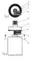
- Fig. 1 is a schematic lateral view of a first embodiment,
- fig. 2 shows a section along II-II in fig. 1,
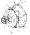
- fig. 3 is a perspective view of a second embodiment, seen from the front,
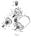
- fig. 4 is an exploded view thereof,
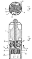
- fig. 5 shows a longitudinal section through an embodiment with a planetary gear, and
- fig. 6 shows a cross-section along VI-VI in the embodiment shown in fig. 5.
-
- The embodiment illustrated in figs. 1 and 2 comprises a 12V or
24V DC motor 1, where aworm 2 is formed in an extended part of the motor shaft. Theworm 2, which is of steel, drives aworm wheel 3 and a pinion 4 which as a unit are moulded in plastics. The pinion 4 drives acrown wheel 5 which is likewise of plastics. The crown wheel has a power take-off for connection with the subsequent transmission. Mounting of the unit worm wheel pinion and crown wheel may be performed in the housing or frame of the actuator, but an attractive way is mounting on the motor, an example being given in the following. - The pinion 4 is cylindrical here, and the same applies to the crown wheel.
- Using the same reference numerals for the same parts, the embodiment shown in fig. 3 likewise comprises a 12 or 24V DC motor or other form of
servomotor 1. In contrast to the foregoing embodiment, there are here two sets of worm wheels and pinions 3a, 4a; 3b,4b which are arranged diametrically opposite, with the advantages that the forces are distributed and the load on the toothed wheels is reduced, just as the worm and the crown wheel are prevented from flexing outwards. - As will appear from fig. 4, the motor housing is here provided with a
front cover 7 moulded in lightweight metal. Thiscover 7 has two forwardly directedbrackets 8a, 8b, each with a shaft 9a, 9b, for a worm and pinion 3a, 4a; 3b, 4b which is secured on the shafts with a locking ring in a groove on the end of the shafts. The shafts 9a, 9b are steel shafts which are secured with the end in a well 9a' on the brackets intended for the purpose. - Forwardly, the
brackets 8a, 8b merge into acylinder 10 positioned between these. The end of the cylinder facing inwards toward the motor has a hole with an inserted bearingbushing 11, in which the end of theworm 2 is mounted. In addition to being stabilized in the centre by the twoworm wheels 3a, 3b, the worm is thus also prevented from flexing by mounting of the end. - A forwardly directed
shaft 12, which is arranged in extension of the motor shaft, is provided at the opposite end of thecylinder 10. Theshaft 12 is shown here as a loose steel shaft secured in a hole in the cylinder, but the shaft may also be moulded integrally with the cylinder, as indicated in fig. 5. A bearing bushing 13 is arranged on theshaft 12, secured against rotation by longitudinal grooves and splines, just as the bushing is secured on the shaft by alocking washer 14. - Integrally moulded with the
crown wheel 5 is atoothed wheel 15 which forms a sun wheel in a subsequent planetary gear. Thesun wheel 15 gives an extra long bearing face for the crown wheel as a whole. Thecrown wheel 5 is mounted here on the bearing bushing 13 and secured against skidding by acollar 16, which is received in arecess 17 at the end of the sun wheel. The crown wheel may be moulded with a two-jawed tool, where the dividing face is at the root 5' of the toothing of the crown wheel, and so may worm pinion, with the parting face being naturally positioned at the dividing line between these. - The
front cover 7 is positioned on the motor housing with two sets offlaps 18a, 18b which are received incorresponding incisions 19a, 19b. Theflaps 20a, 20b between the two pairs of incisions are used for securing thecover 7, in that the flaps are pressed inwardly over the outer side of the cover, alternatively in that the edge of the motor housing against theflaps - Figs. 5 and 6 show an embodiment with a
planetary gear 21 after the crown wheel. The principle is generally as shown in figs. 3 and 4, and the same parts have the same reference numerals. The appearance of worm wheel/crown wheel in fig. 5 is due to the way in which the section is made. The planetary gear is here incorporated in ahousing 25, which with one end fits over worm, worm wheel/pinion and crown wheel. The housing includes atransverse wall 22 with a bore for thetoothed wheel 15 of the crown wheel, which protrudes into the other end of the housing and meshes with aplanetary wheel 26, which in turn meshes with aninternal toothing 23 in the housing. Thetoothed wheel 15 of the crown wheel thus forms a sun wheel in the planetary gear. Thehousing 25 is secured to the motor housing bysnap locking legs 24 formed in thefront cover 7. The ends of thesnap locking legs 24 engage with mating notches on the inner side of the housing. The planetary gear as a whole may thus be snapped firmly on to the front end of the motor. - As will appear, the structure is compact in the transverse as well as in the longitudinal direction. There is a good and balanced distribution of forces. The crown wheel is firmly mounted and additionally supported by two diametrically positioned pinions. The structure is composed of few parts which are easy to assemble. The gearing is relatively high. The order 1:30 may be given by way of example, distributed equally between worm/worm wheel and pinion crown wheel. In addition, the transmission has a low level of noise. Finally, the advantage of in-line gearing should be mentioned, i.e. with the drive shaft in extension of the motor shaft.
Claims (10)
- An actuator wherein an electric motor (1) drives an activation element, such as a rotatable arm or a longitudinally movable piston rod, via a transmission, and wherein the transmission has at least two transmission stages, the first one being a worm drive with a worm (2) and a worm wheel (3) and the subsequent one having a power take-off (6, 15) , characterized in that the subsequent transmission stage is formed by a cylindrical crown wheel and cylindrical pinion (5, 4), wherein the pinion (4) is driven by the worm wheel, (3), and wherein the crown wheel fronts the worm drive and has said power take-off (6, 15), said power take-off being arranged in extension of or substantially in extension of the worm (2).
- An actuator according to claim 1, characterized in that the transmission comprises an additional worm wheel (3b) and pinion (4b) arranged diametrically opposite the first worm and pinion (3a, 4a).
- An actuator according to claim 1 or 2, characterized in that worm wheel and pinion (3, 4; 3a,4a; 3b,4b) are formed in one piece.
- An actuator according to claim 1, characterized in that the motor housing has a front cover (7) with shafts (9a, 9b) for worm wheel/pinion (3a, 4a; 3b,4b) and a shaft (12) for the crown wheel (5).
- An actuator according to claim 1, characterized in that the power take-off of the crown wheel (5) is formed as an axis-parallel toothed wheel (15).
- An actuator according to claim 5, characterized in that crown wheel and toothed wheel (5, 15) are formed in one piece.
- An actuator according to claim 4, characterized in that the shaft (12) of the crown wheel (5) is provided with a bearing bushing (13).
- An actuator according to claim 4, characterized in that the free end of the worm (2) is mounted in a bearing bushing (11) in the front cover (7).
- An actuator according to claim 5, characterized in that the transmission additionally comprises a planetary gear (21) in which a sun wheel is formed by the axis-parallel toothed wheel (15) on the crown wheel (5).
- An actuator according to any one of the preceding claims, characterized in that worm wheel, pinion and crown wheel with said power take-off in the form of a toothed wheel are of plastics.
Applications Claiming Priority (3)
| Application Number | Priority Date | Filing Date | Title |
|---|---|---|---|
| DKPA200000534 | 2000-03-31 | ||
| DK200000534 | 2000-03-31 | ||
| PCT/DK2001/000211 WO2001075334A1 (en) | 2000-03-31 | 2001-03-28 | Actuator |
Publications (2)
| Publication Number | Publication Date |
|---|---|
| EP1272778A1 EP1272778A1 (en) | 2003-01-08 |
| EP1272778B1 true EP1272778B1 (en) | 2004-06-23 |
Family
ID=8159391
Family Applications (1)
| Application Number | Title | Priority Date | Filing Date |
|---|---|---|---|
| EP01915125A Expired - Lifetime EP1272778B1 (en) | 2000-03-31 | 2001-03-28 | Actuator |
Country Status (9)
| Country | Link |
|---|---|
| US (1) | US6770006B2 (en) |
| EP (1) | EP1272778B1 (en) |
| JP (1) | JP2003529731A (en) |
| CN (1) | CN1177156C (en) |
| AT (1) | ATE269948T1 (en) |
| AU (2) | AU4232501A (en) |
| DE (1) | DE60103992T2 (en) |
| DK (1) | DK1272778T3 (en) |
| WO (1) | WO2001075334A1 (en) |
Cited By (3)
| Publication number | Priority date | Publication date | Assignee | Title |
|---|---|---|---|---|
| WO2009146707A1 (en) | 2008-06-06 | 2009-12-10 | Linak A/S | Gear with at least two gearing stages, a linear actuator comprising such a gear and a table leg comrising such a linear actuator |
| EP2166252A1 (en) | 2008-09-17 | 2010-03-24 | Karlheinz Baumeister | Worm gear |
| EP3044478B1 (en) | 2013-09-11 | 2018-01-03 | GAPOSA S.r.l. | Tubular actuating mechanism for roll-type closures |
Families Citing this family (21)
| Publication number | Priority date | Publication date | Assignee | Title |
|---|---|---|---|---|
| WO2001017401A1 (en) | 1999-09-02 | 2001-03-15 | Linak A/S | Rotary actuator, especially for adjustable furniture, including beds and bottom for beds |
| DE10303205A1 (en) * | 2003-01-28 | 2004-07-29 | Zf Friedrichshafen Ag | Angled drive in form of crown wheel drive has star wheel and crown wheel and is combined with worm drive to give large transmission ratios, whereby star wheel and worm wheel form pinion of crown wheel |
| US7934459B2 (en) * | 2005-09-20 | 2011-05-03 | Brian Frazier | Ergonomic workstation with raising and lowering elements |
| DE202005020106U1 (en) * | 2005-12-23 | 2007-05-10 | Marantec Antriebs- Und Steuerungstechnik Gmbh & Co. Kg | gearmotor |
| CN100432482C (en) * | 2007-01-30 | 2008-11-12 | 重庆大学 | Planetary gear transmission reducer |
| US8096329B2 (en) * | 2007-06-15 | 2012-01-17 | S. C. Johnson & Son, Inc. | Hand-held vacuum pump |
| US7967509B2 (en) | 2007-06-15 | 2011-06-28 | S.C. Johnson & Son, Inc. | Pouch with a valve |
| DK2232100T3 (en) * | 2008-01-12 | 2013-01-02 | Linak As | LINEAR ACTUATOR |
| US9155391B2 (en) * | 2008-06-06 | 2015-10-13 | Linak A/S | Linear actuator |
| FR2957628B1 (en) * | 2010-03-19 | 2012-04-20 | Somfy Sas | REDUCER AND ELECTRIC ACTUATOR COMPRISING SUCH A REDUCER |
| IT1399837B1 (en) * | 2010-05-04 | 2013-05-03 | Automatismi Beninca S P A | DRIVING DEVICE FOR AUTOMATIC DOORS |
| DE102012221020A1 (en) * | 2012-11-19 | 2014-05-22 | ebm-papst ZEITLAUF GmbH & Co. KG | angle gear |
| US20160091052A1 (en) * | 2014-09-25 | 2016-03-31 | Moatech Co., Ltd. | Actuator and electronic equipment having the same |
| JP6686373B2 (en) * | 2014-12-01 | 2020-04-22 | 株式会社デンソー | Actuator |
| JP6609916B2 (en) * | 2014-12-01 | 2019-11-27 | 株式会社デンソー | Actuator |
| US9777797B2 (en) | 2014-12-01 | 2017-10-03 | Asmo Co., Ltd. | Actuator |
| DE102017207931A1 (en) * | 2017-05-10 | 2018-11-15 | Mahle International Gmbh | Modular system for producing an adjusting device |
| ES2858073T3 (en) * | 2017-05-24 | 2021-09-29 | Ims Gear Se & Co Kgaa | Pair of sprockets for a worm gear, worm gear with such a pair of sprockets, as well as use of such a pair of sprockets in worm gears |
| IT201700064228A1 (en) * | 2017-06-09 | 2018-12-09 | Harjinder Singh | ADAPTER |
| CN107269768B (en) * | 2017-06-30 | 2023-06-30 | 常州市凯迪电器股份有限公司 | Reduction gear |
| TWI803397B (en) * | 2022-07-21 | 2023-05-21 | 施權航 | electric bed |
Family Cites Families (21)
| Publication number | Priority date | Publication date | Assignee | Title |
|---|---|---|---|---|
| US3552225A (en) * | 1968-10-24 | 1971-01-05 | Donald M Van Voorhis | Internal worm and speed reducer using an internal worm |
| US3645148A (en) * | 1970-06-15 | 1972-02-29 | Pitney Bowes Inc | Skew axis gearing |
| US3765260A (en) * | 1972-09-01 | 1973-10-16 | Us Army | Load limiting mechanism |
| US4026163A (en) * | 1973-05-24 | 1977-05-31 | Fmc Corporation | Double speed reducer unit assembly |
| US3949626A (en) * | 1974-07-24 | 1976-04-13 | Quaker City Gear Works, Inc. | Differential gear system and actuator assembly |
| GB1464770A (en) * | 1976-01-16 | 1977-02-16 | Fmc Corp | Speed reducers |
| US4504239A (en) * | 1983-01-31 | 1985-03-12 | Marvin Glass & Associates | Toy land vehicle and aircraft combination |
| GB2182733A (en) * | 1985-10-31 | 1987-05-20 | Alan Kam Kit Yuen | Limited slip differential gears for motor vehicles |
| US4700589A (en) * | 1986-02-14 | 1987-10-20 | Coronel Paul K | Coronel radiant drive systems |
| JPH03501765A (en) * | 1988-10-20 | 1991-04-18 | アイヴィジー オーストラリア プロプライアテリー リミテド | Rotary drive control mechanism |
| DE3920861A1 (en) * | 1989-06-07 | 1990-12-13 | Gkn Automotive Ag | GEARBOX |
| US5102019A (en) * | 1990-10-11 | 1992-04-07 | Lam Peter A | Motorized adjustable clothes hanger |
| EP0510360B1 (en) * | 1991-04-03 | 1995-06-14 | Jankovic, Milan | Suction device to create a vacuum in containers |
| JP2949604B2 (en) * | 1991-04-08 | 1999-09-20 | 自動車機器株式会社 | Electric power steering system |
| DK86292A (en) | 1992-06-30 | 1993-12-31 | Linak As | LINEAR ACTUATOR |
| DE4309559B4 (en) * | 1993-03-24 | 2005-11-10 | Sew-Eurodrive Gmbh & Co. Kg | Axis offset angular gear |
| ATE179584T1 (en) * | 1993-05-28 | 1999-05-15 | Koninkl Philips Electronics Nv | TOOTHBRUSH |
| DK4094A (en) | 1994-01-10 | 1995-07-11 | Linak As | Linear actuator |
| JP3181191B2 (en) * | 1995-05-24 | 2001-07-03 | 株式会社ユーシン | Actuator |
| JPH09100890A (en) * | 1995-10-03 | 1997-04-15 | Mitsuba Corp | Actuator |
| TW443670U (en) * | 1999-10-14 | 2001-06-23 | Hiwin Mikrosystem Corp | An anti-slipout type linear screw actuator |
-
2001
- 2001-03-28 DE DE60103992T patent/DE60103992T2/en not_active Expired - Lifetime
- 2001-03-28 JP JP2001572778A patent/JP2003529731A/en active Pending
- 2001-03-28 AU AU4232501A patent/AU4232501A/en active Pending
- 2001-03-28 CN CNB018072968A patent/CN1177156C/en not_active Expired - Lifetime
- 2001-03-28 WO PCT/DK2001/000211 patent/WO2001075334A1/en not_active Ceased
- 2001-03-28 US US10/240,214 patent/US6770006B2/en not_active Expired - Lifetime
- 2001-03-28 EP EP01915125A patent/EP1272778B1/en not_active Expired - Lifetime
- 2001-03-28 AT AT01915125T patent/ATE269948T1/en not_active IP Right Cessation
- 2001-03-28 AU AU2001242325A patent/AU2001242325B2/en not_active Ceased
- 2001-03-28 DK DK01915125T patent/DK1272778T3/en active
Cited By (3)
| Publication number | Priority date | Publication date | Assignee | Title |
|---|---|---|---|---|
| WO2009146707A1 (en) | 2008-06-06 | 2009-12-10 | Linak A/S | Gear with at least two gearing stages, a linear actuator comprising such a gear and a table leg comrising such a linear actuator |
| EP2166252A1 (en) | 2008-09-17 | 2010-03-24 | Karlheinz Baumeister | Worm gear |
| EP3044478B1 (en) | 2013-09-11 | 2018-01-03 | GAPOSA S.r.l. | Tubular actuating mechanism for roll-type closures |
Also Published As
| Publication number | Publication date |
|---|---|
| JP2003529731A (en) | 2003-10-07 |
| CN1419636A (en) | 2003-05-21 |
| US6770006B2 (en) | 2004-08-03 |
| ATE269948T1 (en) | 2004-07-15 |
| WO2001075334A1 (en) | 2001-10-11 |
| DE60103992D1 (en) | 2004-07-29 |
| DK1272778T3 (en) | 2004-11-01 |
| CN1177156C (en) | 2004-11-24 |
| US20030101837A1 (en) | 2003-06-05 |
| DE60103992T2 (en) | 2005-07-14 |
| AU4232501A (en) | 2001-10-15 |
| EP1272778A1 (en) | 2003-01-08 |
| AU2001242325B2 (en) | 2005-04-07 |
Similar Documents
| Publication | Publication Date | Title |
|---|---|---|
| AU2001242325B2 (en) | Actuator | |
| AU2001242325A1 (en) | Actuator | |
| EP1217922B1 (en) | Rotary actuator, especially for adjustable furniture, including beds and bottom for beds | |
| EP2232101B1 (en) | Linear actuator | |
| EP2288821B1 (en) | Gear with at least two gearing stages, a linear actuator comprising such a gear and a table leg comrising such a linear actuator | |
| US8312579B2 (en) | Pivoting device | |
| EP1621055B1 (en) | An actuator | |
| WO2005122840A8 (en) | A linear actuator for beds, slatted beds or chairs | |
| US5398904A (en) | Gear reducer | |
| US10495206B2 (en) | Internal ring gear, driving assembly and application device | |
| KR20160106565A (en) | Seat cushion length adjusting device and method of adjusting a seat cushion length | |
| EP1018312B1 (en) | Drive for mechanical adjustment of profile parts; piece of furniture, profile part and method for manufacturing a profile part | |
| WO2004020870A1 (en) | Linear actuator and method of minimizing axial movement of the spindle | |
| CN114123643A (en) | Electric actuator and power transmission component thereof | |
| CN101435487B (en) | Gear drive mechanism of rotating shaver | |
| CN219077063U (en) | Adjustment mechanism and adjustable equipment | |
| RU2811111C2 (en) | Electric motor adjustment unit for adjusting tilt of supporting part of seating furniture containing electric motor adjustment unit and seating furniture | |
| RU2810358C2 (en) | Electric motor adjustment unit for adjusting tilt of supporting part of seating furniture, supporting part of seating furniture and seating furniture | |
| CN120175814A (en) | A gear box structure | |
| EP1375272A2 (en) | Actuator | |
| HK1027494A (en) | Furniture for sitting/lying, especially slatted frame, with adjustable elements |
Legal Events
| Date | Code | Title | Description |
|---|---|---|---|
| PUAI | Public reference made under article 153(3) epc to a published international application that has entered the european phase |
Free format text: ORIGINAL CODE: 0009012 |
|
| 17P | Request for examination filed |
Effective date: 20021028 |
|
| AK | Designated contracting states |
Kind code of ref document: A1 Designated state(s): AT BE CH CY DE DK ES FI FR GB GR IE IT LI LU MC NL PT SE TR |
|
| AX | Request for extension of the european patent |
Free format text: AL;LT;LV;MK;RO;SI |
|
| 17Q | First examination report despatched |
Effective date: 20030909 |
|
| GRAP | Despatch of communication of intention to grant a patent |
Free format text: ORIGINAL CODE: EPIDOSNIGR1 |
|
| GRAS | Grant fee paid |
Free format text: ORIGINAL CODE: EPIDOSNIGR3 |
|
| GRAA | (expected) grant |
Free format text: ORIGINAL CODE: 0009210 |
|
| AK | Designated contracting states |
Kind code of ref document: B1 Designated state(s): AT BE CH CY DE DK ES FI FR GB GR IE IT LI LU MC NL PT SE TR |
|
| PG25 | Lapsed in a contracting state [announced via postgrant information from national office to epo] |
Ref country code: TR Free format text: LAPSE BECAUSE OF FAILURE TO SUBMIT A TRANSLATION OF THE DESCRIPTION OR TO PAY THE FEE WITHIN THE PRESCRIBED TIME-LIMIT Effective date: 20040623 Ref country code: AT Free format text: LAPSE BECAUSE OF FAILURE TO SUBMIT A TRANSLATION OF THE DESCRIPTION OR TO PAY THE FEE WITHIN THE PRESCRIBED TIME-LIMIT Effective date: 20040623 Ref country code: BE Free format text: LAPSE BECAUSE OF FAILURE TO SUBMIT A TRANSLATION OF THE DESCRIPTION OR TO PAY THE FEE WITHIN THE PRESCRIBED TIME-LIMIT Effective date: 20040623 Ref country code: FI Free format text: LAPSE BECAUSE OF FAILURE TO SUBMIT A TRANSLATION OF THE DESCRIPTION OR TO PAY THE FEE WITHIN THE PRESCRIBED TIME-LIMIT Effective date: 20040623 |
|
| REG | Reference to a national code |
Ref country code: GB Ref legal event code: FG4D |
|
| REG | Reference to a national code |
Ref country code: CH Ref legal event code: EP |
|
| REG | Reference to a national code |
Ref country code: IE Ref legal event code: FG4D |
|
| REF | Corresponds to: |
Ref document number: 60103992 Country of ref document: DE Date of ref document: 20040729 Kind code of ref document: P |
|
| REG | Reference to a national code |
Ref country code: CH Ref legal event code: NV Representative=s name: TROESCH SCHEIDEGGER WERNER AG |
|
| PG25 | Lapsed in a contracting state [announced via postgrant information from national office to epo] |
Ref country code: GR Free format text: LAPSE BECAUSE OF FAILURE TO SUBMIT A TRANSLATION OF THE DESCRIPTION OR TO PAY THE FEE WITHIN THE PRESCRIBED TIME-LIMIT Effective date: 20040923 |
|
| PG25 | Lapsed in a contracting state [announced via postgrant information from national office to epo] |
Ref country code: ES Free format text: LAPSE BECAUSE OF FAILURE TO SUBMIT A TRANSLATION OF THE DESCRIPTION OR TO PAY THE FEE WITHIN THE PRESCRIBED TIME-LIMIT Effective date: 20041004 |
|
| REG | Reference to a national code |
Ref country code: SE Ref legal event code: TRGR |
|
| REG | Reference to a national code |
Ref country code: DK Ref legal event code: T3 |
|
| LTIE | Lt: invalidation of european patent or patent extension |
Effective date: 20040623 |
|
| ET | Fr: translation filed | ||
| PG25 | Lapsed in a contracting state [announced via postgrant information from national office to epo] |
Ref country code: LU Free format text: LAPSE BECAUSE OF NON-PAYMENT OF DUE FEES Effective date: 20050328 Ref country code: CY Free format text: LAPSE BECAUSE OF FAILURE TO SUBMIT A TRANSLATION OF THE DESCRIPTION OR TO PAY THE FEE WITHIN THE PRESCRIBED TIME-LIMIT Effective date: 20050328 Ref country code: IE Free format text: LAPSE BECAUSE OF NON-PAYMENT OF DUE FEES Effective date: 20050328 |
|
| PG25 | Lapsed in a contracting state [announced via postgrant information from national office to epo] |
Ref country code: MC Free format text: LAPSE BECAUSE OF NON-PAYMENT OF DUE FEES Effective date: 20050331 |
|
| PLBE | No opposition filed within time limit |
Free format text: ORIGINAL CODE: 0009261 |
|
| STAA | Information on the status of an ep patent application or granted ep patent |
Free format text: STATUS: NO OPPOSITION FILED WITHIN TIME LIMIT |
|
| 26N | No opposition filed |
Effective date: 20050324 |
|
| REG | Reference to a national code |
Ref country code: IE Ref legal event code: MM4A |
|
| PG25 | Lapsed in a contracting state [announced via postgrant information from national office to epo] |
Ref country code: PT Free format text: LAPSE BECAUSE OF NON-PAYMENT OF DUE FEES Effective date: 20041123 |
|
| PGFP | Annual fee paid to national office [announced via postgrant information from national office to epo] |
Ref country code: GB Payment date: 20080220 Year of fee payment: 8 Ref country code: IT Payment date: 20080313 Year of fee payment: 8 |
|
| PGFP | Annual fee paid to national office [announced via postgrant information from national office to epo] |
Ref country code: FR Payment date: 20080320 Year of fee payment: 8 |
|
| PGFP | Annual fee paid to national office [announced via postgrant information from national office to epo] |
Ref country code: DK Payment date: 20090326 Year of fee payment: 9 |
|
| PGFP | Annual fee paid to national office [announced via postgrant information from national office to epo] |
Ref country code: NL Payment date: 20090331 Year of fee payment: 9 |
|
| PGFP | Annual fee paid to national office [announced via postgrant information from national office to epo] |
Ref country code: SE Payment date: 20090327 Year of fee payment: 9 |
|
| PGFP | Annual fee paid to national office [announced via postgrant information from national office to epo] |
Ref country code: CH Payment date: 20090527 Year of fee payment: 9 |
|
| GBPC | Gb: european patent ceased through non-payment of renewal fee |
Effective date: 20090328 |
|
| REG | Reference to a national code |
Ref country code: FR Ref legal event code: ST Effective date: 20091130 |
|
| PG25 | Lapsed in a contracting state [announced via postgrant information from national office to epo] |
Ref country code: FR Free format text: LAPSE BECAUSE OF NON-PAYMENT OF DUE FEES Effective date: 20091123 Ref country code: GB Free format text: LAPSE BECAUSE OF NON-PAYMENT OF DUE FEES Effective date: 20090328 |
|
| REG | Reference to a national code |
Ref country code: NL Ref legal event code: V1 Effective date: 20101001 |
|
| REG | Reference to a national code |
Ref country code: CH Ref legal event code: PL |
|
| EUG | Se: european patent has lapsed | ||
| REG | Reference to a national code |
Ref country code: DK Ref legal event code: EBP |
|
| PG25 | Lapsed in a contracting state [announced via postgrant information from national office to epo] |
Ref country code: NL Free format text: LAPSE BECAUSE OF NON-PAYMENT OF DUE FEES Effective date: 20101001 |
|
| PG25 | Lapsed in a contracting state [announced via postgrant information from national office to epo] |
Ref country code: LI Free format text: LAPSE BECAUSE OF NON-PAYMENT OF DUE FEES Effective date: 20100331 Ref country code: CH Free format text: LAPSE BECAUSE OF NON-PAYMENT OF DUE FEES Effective date: 20100331 |
|
| PG25 | Lapsed in a contracting state [announced via postgrant information from national office to epo] |
Ref country code: IT Free format text: LAPSE BECAUSE OF NON-PAYMENT OF DUE FEES Effective date: 20090328 |
|
| PG25 | Lapsed in a contracting state [announced via postgrant information from national office to epo] |
Ref country code: DK Free format text: LAPSE BECAUSE OF NON-PAYMENT OF DUE FEES Effective date: 20100331 |
|
| PG25 | Lapsed in a contracting state [announced via postgrant information from national office to epo] |
Ref country code: SE Free format text: LAPSE BECAUSE OF NON-PAYMENT OF DUE FEES Effective date: 20100329 |
|
| PGFP | Annual fee paid to national office [announced via postgrant information from national office to epo] |
Ref country code: DE Payment date: 20200320 Year of fee payment: 20 |
|
| REG | Reference to a national code |
Ref country code: DE Ref legal event code: R071 Ref document number: 60103992 Country of ref document: DE |